US7190444B1 - System and method of measuring field-of-view of an optical sensor - Google Patents
System and method of measuring field-of-view of an optical sensor Download PDFInfo
- Publication number
- US7190444B1 US7190444B1 US10/862,240 US86224004A US7190444B1 US 7190444 B1 US7190444 B1 US 7190444B1 US 86224004 A US86224004 A US 86224004A US 7190444 B1 US7190444 B1 US 7190444B1
- Authority
- US
- United States
- Prior art keywords
- fov
- slit
- grid
- value
- sensor
- Prior art date
- Legal status (The legal status is an assumption and is not a legal conclusion. Google has not performed a legal analysis and makes no representation as to the accuracy of the status listed.)
- Expired - Lifetime, expires
Links
Images


Classifications
-
- G—PHYSICS
- G01—MEASURING; TESTING
- G01B—MEASURING LENGTH, THICKNESS OR SIMILAR LINEAR DIMENSIONS; MEASURING ANGLES; MEASURING AREAS; MEASURING IRREGULARITIES OF SURFACES OR CONTOURS
- G01B11/00—Measuring arrangements characterised by the use of optical techniques
- G01B11/26—Measuring arrangements characterised by the use of optical techniques for measuring angles or tapers; for testing the alignment of axes
Definitions
- the present invention relates, in general, to measuring the field-of-view of an optical sensor and, more specifically, to a system and method of measuring the field-of-view of an optical sensor using a filtered backprojection algorithm.
- An optical instrument has an optical response that varies as a function of its azimuth and elevation viewing angles from a centered coordinate system. As such, an important characteristic of the instrument is the optical response of the instrument within its field-of-view (FOV). Although two instruments may be built to the same specification, each instrument may have a different optical response. Each instrument, therefore, is individually tested to measure optical response as a function of its FOV, or, stated differently, tested to measure its FOV.
- FOV field-of-view
- a grid of spot measurements requires a two-dimensional grid of evenly spaced points, positioned in an area intercepting the FOV of the instrument. Collimated beams are sent into the instrument, at positions corresponding to the spots on the grid. The response of the instrument to each beam is recorded, forming a set of information describing the instrument's FOV.
- the setup may require a large number of grid points and a large number of collimated beams to measure the FOV, the task may be done in a reasonable amount of time provided that each grid point can be measured quickly. Since the quality of the measurement depends on the number of photons, or the amount of light, in the collimated beam, the setup must include collimated beams that are strong enough to permit each grid point to be measured quickly.
- the collimated beams Providing strong collimated beams for each grid point is not practical, when measuring the FOV of a spectrometer, for example. It is desirable for the collimated beams to exhibit a specified spectrum and include relatively weak collimated beams at some wavelength of the frequency spectrum. These weak collimated beams require a relatively long period of time to collect a sufficient amount of photons. Thus, the FOV measurement also requires a long period of time.
- the present invention addresses such need.
- the present invention provides a method of measuring a field-of-view (FOV) of an optical sensor including the steps of: (a) uniformly illuminating a FOV of the optical sensor; (b) moving, at an angle of motion, a slit across the FOV and illuminating the optical sensor through the slit; (c) measuring an optical response of the sensor through the slit, at evenly spaced positions of the moving slit; (d) changing the angle of motion and repeating steps (b) and (c); (e) repeating step (d) for equally spaced angles of motion; and (f) constructing a two-dimensional map of the FOV of the optical sensor, after completing step (e).
- FOV field-of-view
- Constructing the two-dimensional map of the FOV includes filtering measured data obtained in step (e) using a filtered backprojection algorithm, and interpolating among the filtered measured data to form the two-dimensional map of the FOV.
- Constructing the two-dimensional map of the FOV may also include forming a grid of values corresponding to the measured optical response of the sensor at the evenly spaced positions of the moving slit and the equally spaced angles of motion, and interpolating on the grid to find a value of the FOV at a point on the optical sensor.
- Interpolating on the grid includes estimating the value of the FOV at the point given by coordinates x, y using adjacent values formed on the grid.
- Interpolating on the grid may also include estimating the value of the FOV at the point given by coordinates x, y, using adjacent values formed on the grid, as a function of evenly spaced angles between zero radians and pi radians.
- the present invention provides a method of measuring a field-of-view (FOV) of an optical sensor having circular symmetry, the method including the steps of: (a) uniformly illuminating a FOV of the optical sensor; (b) moving a slit across the FOV and illuminating the optical sensor through the slit; (c) measuring an optical response of the sensor through the slit, at evenly spaced positions across the FOV; and (d) constructing a two-dimensional map of the FOV of the optical sensor, after completing step (c).
- Step (b) includes moving the slit across the FOV in a single direction only.
- Constructing the two-dimensional map of the FOV includes forming a grid of values corresponding to the measured optical response of the sensor at the evenly spaced positions along the single direction, and interpolating on the grid to find a value of the FOV at a point on the optical sensor.
- Interpolating on the grid includes estimating the value of the FOV at the point given by coordinates x, y using adjacent values formed on the grid.
- Interpolating on the grid may also include estimating the value of the FOV at the point given by a distance r from the origin of coordinates x, y using adjacent values formed on the grid, as a function of evenly spaced angles between zero radians and pi radians.
- FIG. 1 is a schematic block diagram of a system for measuring a field-of-view (FOV) of an optical sensor, in accordance with an embodiment of the present invention
- FIG. 2 is a schematic diagram of a moving vertical slit, utilized by the system shown in FIG. 1 , as the slit is moved in various scanning directions (t), at various scan angles ( ⁇ ), and covers the FOV of the optical center, in accordance with a method of the present invention;
- FIG. 3 is a schematic diagram of a moving vertical slit, utilized by the system shown in FIG. 1 , moving in a scan direction, t, and uniformly and simultaneously illuminating multiple FOVs of an array of sensors, in accordance with another embodiment of the present invention
- FIG. 4 is a schematic representation of a vertical slit (or slot) embodied in a plate of the system shown in FIG. 1 , in accordance with an embodiment of the present invention
- FIG. 5 is a two-dimensional map of an exemplary FOV of an optical sensor, in accordance with an embodiment of the present invention.
- FIGS. 6A , 6 B and 6 C are flow diagrams of an embodiment of a method of the present invention, utilizing the system of FIG. 1 , to measure the FOV of the optical system under test;
- FIGS. 7A , 7 B and 7 C are flow diagrams of another embodiment of a method of the invention, utilizing the system of FIG. 1 , to measure the FOV of the optical system under test;
- FIGS. 8A , 8 B and 8 C are flow diagrams of still another embodiment of a method of the invention, utilizing the system of FIG. 1 , to measure the FOV of the optical system under test.
- system 10 for measuring a field-of-view (FOV) of an optical sensor, in accordance with an embodiment of the present invention.
- system 10 includes light source 12 , slotted plate 13 , an optical instrument, device, or sensor under test 18 , image sampler 20 , processor 24 , keyboard 26 , printer/display 28 and motion controller 22 .
- Light source 12 may include any source of light providing a collimated beam 16 with a uniform intensity in an X,Y plane of an X,Y, Z coordinate system.
- Light beam 16 is emitted toward the optical instrument under test, or optical sensor 18 .
- Disposed between light source 12 and optical sensor 18 is slotted plate 13 .
- slotted plate 13 includes an elongated narrow vertical slot, or slit 14 , for permitting passage of portions of light beam 16 through slotted plate 13 .
- Portions of light beam 16 passing through slit 14 are sensed by optical sensor 18 , if the light beam is within the FOV of the sensor.
- the FOV of the sensor generally designated as 17 , is shown as an X,Z plane of the X,Y,Z coordinate system.
- slotted plate 13 may be formed of any material which is opaque to transmission of light.
- the light sensed by optical sensor 18 is preferably due only to the light passing through slit 14 .
- the length of slit 14 in the X direction is preferably made greater than the length of the FOV in the X direction covered by optical sensor 18 , as shown in FIG. 1 . In this manner, the light passing through the slit may cover the entire FOV of optical sensor 18 in one dimension (length), as the slit is moved in any direction perpendicular to that one dimension (length).
- optical sensor 18 The response of optical sensor 18 is measured, as slit 14 passes portions of light beam 16 to the optical sensor.
- motion controller 22 is configured to move slotted plate 13 transversely to its longitudinal slit 14 .
- the longitudinal slit may be moved in an X,Y direction of the X,Y,Z coordinate system 15 , as shown in FIG. 1 , where the Z axis is disposed along the light beam propagation direction.
- processor 24 may print or display the response of sensor 18 to the light. This response may be printed or displayed as a two-dimensional map of the FOV in the X,Y axes (for example) on printer/display 28 .
- processor 24 provides translation directions to slotted plate 13 , in order to move slit 14 in X and Y directions, which are directions perpendicular to the Z direction.
- the present invention provides a method for measuring the optical response of the sensor under test by gathering FOV information or data over a series of runs. Each run provides sensor response data along evenly spaced sample positions along one scan direction t.
- the series of runs is formed by a sequence of individual scan directions that are each separated by an equally spaced angle ⁇ between 0 degrees and 180 degrees.
- system 10 is conducting FOV measurements by simultaneously stimulating multiple FOVs of a large array of closely spaced sensors.
- the array of sensors includes six closely spaced FOVS, designated as 16 a , 16 b , 16 c , 16 d , 16 e and 16 f .
- system 10 may cover and sample three of the six FOVs (for example) at the same time. This advantageously allows the FOV measurements to take place more quickly than the FOV measurements being conducted in the exemplary embodiment of FIG. 2 .
- the invention shown in FIG. 3 measures the optical response of an array of sensors by gathering FOV information over a series of runs. Each run provides sensor response data along evenly spaced sample positions along one scan direction t.
- the methods of the invention utilize the Radon transform to construct a two-dimensional map of the FOV of a sensor under test. More specifically, the present invention uses a filtered backprojection algorithm to obtain the two-dimensional map of the FOV.
- the slits used to gather data have width w, as shown in FIG. 4 .
- N k measurements taken at evenly spaced slit locations along the scan. Adjacent measurements are separated by an interval ⁇ t, as shown in FIG. 2 .
- N j scans at evenly spaced angles between 0 degrees and 180 degrees. Adjacent scans are separated by a change in angle ⁇ in radians.
- a quantity h k is defined by the invention as follows:
- P j,k is defined as a value of the k'th slit measurement along the scan direction, at the j'th angle. Index k runs from 0 to N k ⁇ 1 and index j runs from 0 to N j ⁇ 1.
- Quantity h k is used by the invention to calculate a new array of values, as follows:
- N ⁇ evenly spaced angles between 0 degrees and 180 degrees.
- N ⁇ is preferably larger than N j .
- a function q( ⁇ ,t) is constructed by the invention by linearly interpolating on the grid of Q j,k values. To calculate q( ⁇ ,t), the index values j and k are first found, as follows: t k ⁇ t ⁇ t k+1 and ⁇ j ⁇ j+1
- FIG. 5 is an exemplary map showing two-dimensional FOV data constructed by system 10 , after applying the filtered backprojection algorithm described above.
- the slit width w is about 1% of the length of FOV 16 at the angle of ⁇ equal to 0, as shown for example in FIG. 2 .
- any sensor not just a spectrometer, camera or other type of imager
- Any sensor having a defined FOV may be stimulated through a longitudinal narrow slit, data sampled, and processed to quanitfy its FOV by this procedure.
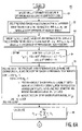
- an exemplary method of measuring a FOV of an optical sensor the method generally designated as 60 .
- the method beginning at step 61 , specifies an X,Y coordinate system having an origin located near a center of the field-of-view.
- the coordinate system is designated as S.
- step 62 specifies evenly spaced angles between 0 radians and pi radians. These evenly spaced angles are separated by ⁇ .
- Step 63 of the method specifies evenly spaced distances for moving the slit (or slot) along a specific angle. ⁇ t is the separation distance between adjacent slit positions.
- h k takes on different values depending on the value of the integer k.
- the value of k may be positive or negative, as the distances of the slit (or slot) may be positioned in a positive direction or a negative direction, about a centered origin in coordinate system S.
- the method provides a light source having a uniform radiance field with a desired spectrum.
- the spectrum may include a wide range of wavelengths, such as the wide range provided by a black body, or the spectrum may include a narrow or specific wavelength.
- the uniform radiance preferably covers the FOV of the sensor.
- the method positions the longitudinal slot, having a width of w, in an X,Y plane of the FOV, such that the center of the slot is disposed at a distance t k from the origin of the coordinate system, at an angle of ⁇ j with respect to the X axis.
- the longitudinal slot is preferably long enough to extend out to a point where the FOV of the optical sensor is zero.
- the light passing through the slot is detected by the optical sensor as a signal.
- the signal detected by the optical sensor is measured and denoted by a value of P j,k .
- step 65 the method re-positions the longitudinal slot for scanning along another direction t at a different angle of ⁇ j .
- the angle of ⁇ j is changed at evenly spaced angles between 0 radians and pi radians.
- the signals detected by the optical sensor are measured in this manner and filtered by the h k filter, defined in step 64 .
- the step of filtering the detected optical sensor signals is performed, as shown by step 66 , to provide a grid of filtered values, each filtered value denoted by Q j,k .
- the method interpolates among the grid of filtered values to form a two-dimensional map of the FOV.
- the interpolation is performed by steps 67 , 68 , 69 , 70 , 71 and 72 .
- the interpolation is calculated to find an X,Y value of the FOV in the coordinate system of S.
- the interpolation is performed by using evenly spaced angles between 0 radians and pi radians, where each angle is denoted by ⁇ i .
- the interpolation is calculated among four adjacent points on the grid of filtered values, which have been calculated in step 66 . As the four adjacent points on the grid have different values of j and k, the method finds the index j and the index k such that the equations shown in steps 69 , 70 and 71 are satisfied.
- each value of G is now the reconstructed (or interpolated) value of the FOV of the optical sensor, at point X,Y in coordinate system S.
- the algorithm executed by method 60 may also be referred to as a modified filtered backprojection algorithm.
- FIGS. 7A , 7 B and 7 C there is shown another exemplary method of measuring a FOV of an optical sensor, the method generally designated as 80 .
- the method beginning at step 81 , specifies an X,Y coordinate system having an origin located near a center of the field-of-view.
- the coordinate system is designated as S.
- step 82 specifies evenly spaced angles between 0 radians and pi radians. These evenly spaced angles are separated by ⁇ .
- step 83 of the method specifies evenly spaced distances for moving the slit (or slot) along a specific angle. ⁇ t is the separation distance between adjacent slit positions.
- h k takes on different values depending on the value of the integer k.
- the value of k may be positive or negative, as the distances of the slit (or slot) may be positioned in a positive direction or a negative direction, about a centered origin in coordinate system S.
- the method provides a light source having a uniform radiance field with a desired spectrum.
- the spectrum may include a wide range of wavelengths, such as the wide range provided by a black body, or the spectrum may include a narrow or specific wavelength.
- the uniform radiance preferably covers the FOV of the sensor.
- the method positions the longitudinal slot, having a width of w, in an X,Y plane of the FOV, such that the center of the slot is disposed at a distance t k from the origin of the coordinate system, at an angle of ⁇ j with respect to the X axis.
- the longitudinal slot is preferably long enough to extend out to a point where the FOV of the optical sensor is zero.
- the light passing through the slot is detected by the optical sensor as a signal.
- the signal detected by the optical sensor is measured and denoted by a value of P j,k .
- step 85 the method re-positions the longitudinal slot for scanning along another direction t at a different angle of ⁇ j .
- the angle of ⁇ j is changed at evenly spaced angles between 0 radians and pi radians.
- the signals detected by the optical sensor are measured in this manner and filtered by the h k filter, defined in step 84 .
- the step of filtering the detected optical sensor signals is performed, as shown by step 86 , to provide a grid of filtered values, each filtered value denoted by Q j,k .
- the method interpolates among the grid of filtered values to form a two-dimensional map of the FOV.
- the interpolation is performed by steps 88 , 89 , 90 , 91 and 92 .
- the interpolation is calculated to find an X,Y value of the FOV in the coordinate system of S.
- the interpolation is calculated among adjacent points on the grid of filtered values, which have been calculated in step 86 . As the adjacent points on the grid have different values of k, the method finds the index k such that the equations shown in steps 89 , 90 and 91 are satisfied.
- the interpolation algorithm performed by method 80 in steps 88 , 89 , 90 , 91 and 92 uses equations that are slightly different from the equations used by method 60 in steps 67 , 68 , 69 , 70 , 71 and 72 ( FIGS. 6B and 6C ).
- Method 80 only interpolates by finding the index k that satisfies the equations executed by steps 89 , 90 and 91 ( FIGS. 7B and 7C ).
- Method 60 interpolates by finding the index j and index k that satisfies the equations executed by steps 69 , 70 and 71 ( FIGS. 6B and 6C ).
- the value of v is 1 in steps 89 , 90 and 91 , making the equations different from the equations executed in steps 69 , 70 and 71 .
- each value of G is now the reconstructed (or interpolated) value of the FOV of the optical sensor, at point X,Y in coordinate system S.
- the algorithm executed by method 80 may also be referred to as a non-modified filtered backprojection algorithm.
- FIGS. 8A , 8 B and 8 C there is shown yet another exemplary method of measuring a FOV of an optical sensor, the method generally designated as 100 .
- the method beginning at step 101 , specifies an X,Y coordinate system having an origin located near a center of the field-of-view.
- the coordinate system is designated as S.
- the method in step 103 , specifies evenly spaced distances for moving the slit (or slot) along one specific angle only.
- the angle ⁇ may be zero.
- ⁇ t is the separation distance between adjacent slit positions.
- h k takes on different values depending on the value of the integer k.
- the value of k may be positive or negative, as the distances of the slit (or slot) may be positioned in a positive direction or a negative direction, about a centered origin in coordinate system S.
- the method provides a light source having a uniform radiance field with a desired spectrum.
- the spectrum may include a wide range of wavelengths, such as the wide range provided by a black body, or the spectrum may include a narrow or specific wavelength.
- the uniform radiance preferably covers the FOV of the sensor.
- the method positions the longitudinal slot, having a width of w, in an X,Y plane of the FOV, such that the center of the slot is disposed at a distance t k from the origin of the coordinate system, at an angle of ⁇ j with respect to the X axis ( ⁇ j may be zero, for example).
- the longitudinal slot is preferably long enough to extend out to a point where the FOV of the optical sensor is zero.
- the light passing through the slot is detected by the optical sensor as a signal.
- the signal detected by the optical sensor is measured and denoted by a value of P k .
- the signals detected by the optical sensor are measured in this manner and filtered by the h k filter, defined in step 104 .
- the step of filtering the detected optical sensor signals is performed, as shown by step 106 , to provide a grid of filtered values, each filtered value denoted by Q k . (Notice that the value of j is fixed).
- the method interpolates among the grid of filtered values to form a two-dimensional map of the FOV.
- the interpolation is performed by steps 107 , 108 , 109 , 110 , 111 and 112 .
- the interpolation is calculated to find an X,Y value of the FOV in the coordinate system of S.
- the interpolation is performed by using evenly spaced angles between 0 radian and pi radian, where each angle is denoted by ⁇ i .
- the interpolation is calculated among adjacent points on the grid of filtered values, which have been calculated in step 106 . As the adjacent points on the grid have different values of k, step 69 finds the index k such that the equations shown in steps 109 , 110 and 111 are satisfied. It will be appreciated that the interpolation, as specified by step 108 uses the distance, r, from the origin of the point in coordinate system S, at which the FOV is to be reconstructed from the P k values.
- each value of G is now the reconstructed (or interpolated) value of the FOV of the optical sensor, at a distance, r, from the origin of coordinate system S.
- the algorithm executed by method 100 may also be referred to as a circularly symmetric filtered backprojection algorithm.
- Method 100 may be used to construct the FOV of an optical sensor known to have a circularly symmetric response to light.
Landscapes
- Physics & Mathematics (AREA)
- General Physics & Mathematics (AREA)
- Length Measuring Devices By Optical Means (AREA)
Abstract
Description
Δφ=π/(N φ−1)
The spacing between these angles is in radians.
φi=iΔφ for i=0,1,2, . . . ,N φ−1
tk≦t<tk+1 and θj≦φ<θj+1
q(φ,t)=(1−v)(1−u)Q j,k +v(1−u)Q j+1,k +vuQ j+1,k+1+(1−v)uQ j,k+1
-
- where
Claims (18)
Priority Applications (1)
| Application Number | Priority Date | Filing Date | Title |
|---|---|---|---|
| US10/862,240 US7190444B1 (en) | 2004-06-07 | 2004-06-07 | System and method of measuring field-of-view of an optical sensor |
Applications Claiming Priority (1)
| Application Number | Priority Date | Filing Date | Title |
|---|---|---|---|
| US10/862,240 US7190444B1 (en) | 2004-06-07 | 2004-06-07 | System and method of measuring field-of-view of an optical sensor |
Publications (1)
| Publication Number | Publication Date |
|---|---|
| US7190444B1 true US7190444B1 (en) | 2007-03-13 |
Family
ID=37833420
Family Applications (1)
| Application Number | Title | Priority Date | Filing Date |
|---|---|---|---|
| US10/862,240 Expired - Lifetime US7190444B1 (en) | 2004-06-07 | 2004-06-07 | System and method of measuring field-of-view of an optical sensor |
Country Status (1)
| Country | Link |
|---|---|
| US (1) | US7190444B1 (en) |
Cited By (3)
| Publication number | Priority date | Publication date | Assignee | Title |
|---|---|---|---|---|
| US20110216310A1 (en) * | 2010-03-05 | 2011-09-08 | Edison Opto Corporation | Optical sensing device with rotating type shading assembly |
| RU2521152C1 (en) * | 2013-03-29 | 2014-06-27 | Открытое акционерное общество "Красногорский завод им. С.А. Зверева" | Installation to measure angular field and to monitor step size of test-object mira lines |
| CN114112964A (en) * | 2021-11-10 | 2022-03-01 | 中国科学院上海技术物理研究所 | Multi-element view field automatic measurement system and method for Fourier infrared spectrometer |
Citations (4)
| Publication number | Priority date | Publication date | Assignee | Title |
|---|---|---|---|---|
| US4724439A (en) | 1984-05-07 | 1988-02-09 | Hughes Aircraft Company | Microwave radiometer using fanbeam inversion |
| US5243351A (en) * | 1992-06-25 | 1993-09-07 | Hughes Aircraft Company | Full aperture image synthesis using rotating strip aperture image measurements |
| US6259396B1 (en) | 1999-08-26 | 2001-07-10 | Raytheon Company | Target acquisition system and radon transform based method for target azimuth aspect estimation |
| US6627893B1 (en) | 2001-03-15 | 2003-09-30 | Koninklijke Philips Electronics, N.V. | Focused rotating slat-hole for gamma cameras |
-
2004
- 2004-06-07 US US10/862,240 patent/US7190444B1/en not_active Expired - Lifetime
Patent Citations (4)
| Publication number | Priority date | Publication date | Assignee | Title |
|---|---|---|---|---|
| US4724439A (en) | 1984-05-07 | 1988-02-09 | Hughes Aircraft Company | Microwave radiometer using fanbeam inversion |
| US5243351A (en) * | 1992-06-25 | 1993-09-07 | Hughes Aircraft Company | Full aperture image synthesis using rotating strip aperture image measurements |
| US6259396B1 (en) | 1999-08-26 | 2001-07-10 | Raytheon Company | Target acquisition system and radon transform based method for target azimuth aspect estimation |
| US6627893B1 (en) | 2001-03-15 | 2003-09-30 | Koninklijke Philips Electronics, N.V. | Focused rotating slat-hole for gamma cameras |
Non-Patent Citations (1)
| Title |
|---|
| Avinash C. Kak et al., "Principles of Computerized Tomographic Imaging", IEEE Press, New York, 1988, pp. 49-57. |
Cited By (5)
| Publication number | Priority date | Publication date | Assignee | Title |
|---|---|---|---|---|
| US20110216310A1 (en) * | 2010-03-05 | 2011-09-08 | Edison Opto Corporation | Optical sensing device with rotating type shading assembly |
| US8184278B2 (en) * | 2010-03-05 | 2012-05-22 | Edison Opto Corporation | Optical sensing device with rotating type shading assembly |
| RU2521152C1 (en) * | 2013-03-29 | 2014-06-27 | Открытое акционерное общество "Красногорский завод им. С.А. Зверева" | Installation to measure angular field and to monitor step size of test-object mira lines |
| CN114112964A (en) * | 2021-11-10 | 2022-03-01 | 中国科学院上海技术物理研究所 | Multi-element view field automatic measurement system and method for Fourier infrared spectrometer |
| CN114112964B (en) * | 2021-11-10 | 2023-09-12 | 中国科学院上海技术物理研究所 | Fourier infrared spectrometer multi-view field automatic measurement system and method |
Similar Documents
| Publication | Publication Date | Title |
|---|---|---|
| US8320661B2 (en) | Apparatus and method for extracting information from electromagnetic energy including target 3D structure and materials | |
| US6181472B1 (en) | Method and system for imaging an object with a plurality of optical beams | |
| US6229913B1 (en) | Apparatus and methods for determining the three-dimensional shape of an object using active illumination and relative blurring in two-images due to defocus | |
| EP1759172B1 (en) | Scanner system and method for registering surfaces | |
| US8736847B2 (en) | Method and apparatus for imaging | |
| CA1303347C (en) | Device and method for determining displacement | |
| EP2430414B1 (en) | Knowledge based spectrometer | |
| US5880845A (en) | Apparatus for measuring the photometric and colorimetrics characteristics of an object | |
| KR900002116B1 (en) | Spectral analyzer and direction indicator | |
| CN113932922A (en) | A polarization spectrum imaging system and method | |
| EP0744600B1 (en) | Spectrophotometer | |
| US7190444B1 (en) | System and method of measuring field-of-view of an optical sensor | |
| EP0181935B1 (en) | Microwave radiometer using fanbeam inversion | |
| CN106672893B (en) | Tunable Filters and Tunable Filter Arrays | |
| CN106525239A (en) | Grating-type imaging spectrograph spatial spectral radiation brightness responsivity calibration device and method | |
| US20180195902A1 (en) | Titled filter imaging spectrometer | |
| DE4105509C2 (en) | Scattered light measuring arrangement for examining the surface roughness | |
| US4433245A (en) | Fraunhofer line discriminator | |
| US5237388A (en) | Polarized light measuring apparatus and phase plate measuring apparatus | |
| Aime et al. | Measurement of submilliarcsecond speckle displacements using a cross spectrum analysis technique-Test on atmospheric dispersion | |
| Gault et al. | Divided-mirror scanning technique for a small Michelson interferometer | |
| US11029214B2 (en) | Method and device for analysing an electromagnetic wave in high definition | |
| US6529639B1 (en) | Modulation transfer function characterization employing phased slit reticle | |
| RU2068175C1 (en) | Broadband spectrozonal analyzer | |
| US7355705B1 (en) | Using a fixed-frequency oscillation in a dispersive spectrometer to measure scene inhomogeneity |
Legal Events
| Date | Code | Title | Description |
|---|---|---|---|
| AS | Assignment |
Owner name: ITT MANUFACTURING ENTERPRISES, INC., DELAWARE Free format text: ASSIGNMENT OF ASSIGNORS INTEREST;ASSIGNOR:COHEN, DOUGLAS L.;REEL/FRAME:015444/0418 Effective date: 20040527 |
|
| STCF | Information on status: patent grant |
Free format text: PATENTED CASE |
|
| FPAY | Fee payment |
Year of fee payment: 4 |
|
| AS | Assignment |
Owner name: EXELIS INC., VIRGINIA Free format text: ASSIGNMENT OF ASSIGNORS INTEREST;ASSIGNOR:ITT MANUFACTURING ENTERPRISES LLC (FORMERLY KNOWN AS ITT MANUFACTURING ENTERPRISES, INC.);REEL/FRAME:027567/0656 Effective date: 20111221 |
|
| FPAY | Fee payment |
Year of fee payment: 8 |
|
| AS | Assignment |
Owner name: HARRIS CORPORATION, FLORIDA Free format text: MERGER;ASSIGNOR:EXELIS INC.;REEL/FRAME:039362/0534 Effective date: 20151223 |
|
| MAFP | Maintenance fee payment |
Free format text: PAYMENT OF MAINTENANCE FEE, 12TH YEAR, LARGE ENTITY (ORIGINAL EVENT CODE: M1553); ENTITY STATUS OF PATENT OWNER: LARGE ENTITY Year of fee payment: 12 |