US7184039B2 - Computer-implemented method for generating coarse level meshes for multi-resolution surface editing - Google Patents
Computer-implemented method for generating coarse level meshes for multi-resolution surface editing Download PDFInfo
- Publication number
- US7184039B2 US7184039B2 US09/852,906 US85290601A US7184039B2 US 7184039 B2 US7184039 B2 US 7184039B2 US 85290601 A US85290601 A US 85290601A US 7184039 B2 US7184039 B2 US 7184039B2
- Authority
- US
- United States
- Prior art keywords
- computer
- level mesh
- points
- mesh representation
- generator module
- Prior art date
- Legal status (The legal status is an assumption and is not a legal conclusion. Google has not performed a legal analysis and makes no representation as to the accuracy of the status listed.)
- Expired - Lifetime, expires
Links
Images


Classifications
-
- G—PHYSICS
- G06—COMPUTING OR CALCULATING; COUNTING
- G06T—IMAGE DATA PROCESSING OR GENERATION, IN GENERAL
- G06T17/00—Three-dimensional [3D] modelling for computer graphics
- G06T17/20—Finite element generation, e.g. wire-frame surface description, tesselation
Definitions
- the invention relates generally to the field of computer graphics, and more specifically to generation of meshes representing surfaces of objects.
- the invention specifically provides a computer graphics system and computer-implemented method for generating a coarse-level mesh from a fine-level mesh, which may be used in multi-resolution surface editing.
- objects are represented as surfaces, with the surfaces being represented by meshes.
- a mesh consists of a set of vertices, or points in three-dimensional space, interconnected by edges. The edges define polygonal faces, which may be in the form of triangles, quadrilaterals, and so forth.
- it is desirable to generate a representation of a surface at a finer resolution than a current representation.
- There are several popular methodologies for generating a representation of a surface at a finer resolution than a current representation including a Catmull-Clark surface subdivision methodology and a Loop surface subdivision methodology.
- the methodology described in Zorin relies on a method for smoothing triangular meshes that is described in G. Taubin, “A signal processing approach to fair surface design,” SIGGRAPH 1995, Computer Graphics Conference Proceedings, pp. 351–358.
- Taubin's smoothing methodology consists of two linear filtering steps, the first being a low-pass filter step, followed by a high-pass filter step.
- the high-pass filter step is used to cancel out a mesh-shrinking effect that is induced by the low-pass filter step.
- the filtering operations described by Taubin have the problem that, as a consequence of the linearity of the filtering procedure, artifacts referred to as Gibbs ripples are introduced in the smoothed mesh as a result of discontinuities in the input mesh.
- Taubin's filtering When used in generating a coarse level mesh, Taubin's filtering produces Gibbs ripples at the places on the surface where the fine level mesh has sharp variations. Although Taubin's smoothing methodology may be configured with the help of parameters, no filter can play the role of an inverse of the Loop subdivision rule. Accordingly, in a multi-resolution representation of a Loop subdivision surface, there will be redundant detail information.
- the invention provides a new and improved system and method for generating a coarse-level mesh from a fine-level mesh, which may be used in multi-resolution surface editing.
- the invention provides an arrangement for generating a coarse (“j”) level mesh representing a surface, from a finer (“j+1”) level mesh surface representation.
- the arrangement includes an indicator value generator and a coarse level mesh generator.
- the indicator value generator for respective ones of the points in the finer level mesh surface representation, evaluates an indicator function, the value indicating whether a subdivision-inverse filter methodology or a least-squares optimization methodology is to be used to determine a position for the corresponding point in the coarse level mesh representation.
- the coarse level mesh generator determines, for each of the points that is to be provided in the coarse level mesh representation, a position in response to the position of the corresponding point in the finer level mesh representation, in accordance with the one of the subdivision-inverse filter methodology or least-squares optimization methodology indicated by the indicator value generated by the indicator value generator.
- FIG. 1 depicts a computer graphics system including an arrangement for generating a coarse level mesh representation of a surface from a finer level mesh of a surface, constructed in accordance with the invention
- FIG. 2 depicts a mesh representing a surface to which the Loop surface subdivision methodology has been applied
- FIGS. 3 , 3 A through 3 E depict a mesh representing a surface to which the Catmull-Clark surface subdivision methodology has been applied;
- FIGS. 4 and 5 depict diagrams useful in understanding operations performed by the fine-to-coarse level mesh generating arrangement
- FIGS. 6 , 6 A through 6 E depict a flow chart describing operations performed by the fine-to-coarse level mesh generating arrangement in connection with triangular meshes.
- FIGS. 7 , 7 A through 7 D depict a flow chart describing operations performed by the fine-to-coarse level mesh generating arrangement in connection with quadrilateral meshes.
- FIG. 1 depicts a computer graphics system 10 including an arrangement for generating a coarse level mesh representation of a surface from a finer level mesh of a surface, constructed in accordance with the invention.
- the computer graphics system includes a processor module 11 , one or more operator input devices 12 and one or more display devices 13 .
- the display device(s) 13 will typically comprise a frame buffer, video display terminal or the like, which will display information in textual and/or graphical form on a display screen to the operator.
- the operator input devices 12 for a computer graphics system 10 will typically include a pen 14 which is typically used in conjunction with a digitizing tablet 15 , and a trackball or mouse device 16 . Generally, the pen 14 and digitizing tablet will be used by the operator in several modes.
- the pen 14 and digitizing tablet are used to provide updated shading information to the computer graphics system.
- the pen and digitizing tablet are used by the operator to input conventional computer graphics information, such as line drawing for, for example, surface trimming and other information, to the computer graphics system 10 , thereby to enable the system 10 to perform conventional computer graphics operations.
- the trackball or mouse device 16 can be used to move a cursor or pointer over the screen to particular points in the image at which the operator can provide input with the pen and digitizing tablet.
- the computer graphics system 10 may also include a keyboard (not shown) which the operator can use to provide textual input to the system 10 .
- the processor module 11 generally includes a processor, which may be in the form of one or more microprocessors, a main memory, and will generally include one a mass storage subsystem including one or more disk storage devices.
- the memory and disk storage devices will generally store data and programs (collectively, “information”) to be processed by the processor, and will store processed data which has been generated by the processor.
- the term “memory and disk storage devices” can encompass any computer readable medium, such as a computer hard disk, computer floppy disk, computer readable flash drive, computer-readable RAM or ROM element or equivalent means of encoding digital information on a physical medium.
- programs can encompass any computer program product consisting of computer-readable program instructions encoded on a computer readable medium.
- the processor module includes connections to the operator input device(s) 12 and the display device(s) 13 , and will receive information input by the operator through the operator input device(s) 12 , process the input information, store the processed information in the memory and/or mass storage subsystem.
- the processor module can provide video display information, which can form part of the information obtained from the memory and disk storage device as well as processed data generated thereby, to the display device(s) for display to the operator.
- the processor module 11 may also include connections (not shown) to hardcopy output devices such as printers for facilitating the generation of hardcopy output, modems and/or network interfaces (also not shown) for connecting the system 10 to the public telephony system and/or in a computer network for facilitating the transfer of information, and the like.
- the invention provides an arrangement for generating a coarse-level mesh from a finer level mesh.
- the fine level mesh will continue to be identified by index “j+1,” and the coarse level mesh will continued to be identified by index “j.”
- two surface subdivision methodologies namely the aforementioned Loop surface subdivision methodology and a Catmull-Clark surface subdivision methodology, which are used to generate a finer (“j+1) level mesh from a coarse (“j”) level mesh.
- the invention provides an arrangement for essentially performing, in the case of a triangular mesh, operations that generally provide the inverse of Loop's surface subdivision methodology, and, in the case of a quadrilateral mesh, operations that generally provide the inverse of the Catmull-Clark surface subdivision methodology.
- Loop's surface subdivision methodology will be described in connection with FIG. 2 .
- each triangular face in the original mesh is split into a plurality of subface, the subfaces defining the finer level mesh.
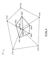
- the vertices of the finer level mesh are positioned using weighted averages of the positions of the vertices in the original mesh. More specifically, and with reference to FIG.
- a mesh 20 at a fine “j” level is depicted that includes a vertex v q 21(0) located at position c j (q), and a plurality “K” of surrounding points v q (1) through v q (K) (generally, v q (k)) 21(1) through 21(K) (generally identified by reference numeral 21( k )) located at positions at respective positions c j (1) through c j (K), the points v q (k) 21( k ) being those points in the mesh 20 that are connected to vertex v q by edges.
- K the number of points connected to vertex v q will sometimes be referred to as the vertex's “valence.”
- a mesh at the next higher fineness level “j+1” corresponds to vertex v′ q 22(0) located at position c j+1 (q) and a set of surrounding points v′ q (1) 22(1) at located at positions c j+1 (l) and connected to the vertex v′ q 22(0).
- the finer level mesh is constructed by providing the vertex v′ q 22(0) at a position c j+1 (q) that is determined by
- Equations (1) and (2) are applied by selecting each point in the mesh at level “j” as a vertex, to provide points for the mesh at level “j+1.” Loop's surface subdivision methodology can be applied recursively to provide a mesh at any desired degree of fineness. It will be appreciated that equation (2) will provide that the point v′ q (1) 22(1) that is created when the methodology is applied to point v q 21(0) as the vertex will be in the same position when the methodology is applied to point v q (k) 21( k ) as the vertex.
- the arrangement processes the points in the finer (“j+1”) level mesh to remove, for each pair of connected points in the finer (“j+1”) level mesh, and determines a position for the remaining point, which will be present in the coarse (“j”) level mesh, based on the positions of surrounding points in the finer (“j+1”) level mesh.
- the operations performed by the arrangement in determining the position of the point that is to remain in the coarse (“j”) level mesh will be described below.
- the Catmull-Clark subdivision methodology produces smooth surfaces using a small number of neighboring vertices.
- the Catmull-Clark surface subdivision methodology will be described in connection with FIGS. 3A through 3E .
- FIG. 3A that FIG. depicts a mesh 30 consisting of four quadrilaterals 31 (1) through 31 (4). Each quadrilateral is referred to as a face.
- the quadrilaterals are defined by points 32 (0), which is common to all of the quadrilaterals 31 (1) through 31 (4), and other points 32 (1) through 32 (8).
- the Catmull-Clark surface subdivision methodology is performed in a series of iterations, including
- each new face point is connected to the edge points of the edges defining the original face
- each new vertex point is connected to the new edge points of all original edges incident on the original vertex point.
- a mesh at the next higher fineness level “j+1” is constructed as follows.
- the face points are generated and located at positions c j+1 (m i ) determined as follows
- c j + 1 ⁇ ( m i ) 1 4 ⁇ ( c j ⁇ ( q ) + c j ⁇ ( l i ) + c j ⁇ ( l i + 1 ) + c j ⁇ ( r i ) ) , m i ⁇ N f ⁇ ( q , j + 1 ) , l i , l i + 1 ⁇ N e ⁇ ( q , j ) , r i ⁇ N f ⁇ ( q , j ) . ( 4 )
- the edge points are generated and located at positions c j+1 (1 i ) determined as follows:
- c j + 1 ⁇ ( l i ) 1 4 ⁇ ( c j ⁇ ( q ) + c j ⁇ ( k i ) + c j + 1 ⁇ ( m i - 1 ) + c j + 1 ⁇ ( m i ) ) , l i ⁇ N e ⁇ ( q , j + 1 ) , k i ⁇ N e ⁇ ( q , j ) , m i - 1 , m i ⁇ N f ⁇ ( q , j + 1 ) ( 5 )
- the new vertex points are generated and located at positions as follows:
- Equation (8) would correspond to the Catmull-Clark methodology (equation (6)) with
- the Catmull-Clark surface subdivision methodology applied to a quadrilateral mesh at the coarse (“j”) level will produce a quadrilateral mesh at the finer (“j+1”) level having the same number of points as the mesh at the coarse (“j”) level, but the points in the finer (“j+1”) level may be at different positions than in the coarse (“j”) level.
- the arrangement processes the points in the finer (“j+1”) level mesh determine a position for each point in the finer (“j+1”) level mesh based on the positions of surrounding points in the finer (“j+1”) level mesh. The operations performed by the arrangement in determining the position of the point in the coarse (“j”) level mesh will be described below.
- the invention provides an arrangement for generating a coarse (“j) level mesh from a finer (“j+1”) level mesh.
- an indicator function is used locally in connection with each point that is being processed as a vertex to determine whether, around the respective point, the fine mesh can be derived by subdivision of a coarser mesh using a subdivision inverse filter.
- the value of the indicator function which will be described below, will be “zero” or close to “zero.”
- the value of the indicator function will not be close to “zero,” and in that case the coarse mesh will be generated using an approximate solution of a least-squares problem.
- the indicator function is constructed for each point, selected as a vertex v′ q , using the value of the Laplacian L(k,j+1) of the positions of the point and of the other points in its neighborhood in the finer (j+1) level mesh.
- L(k,j+1) the Laplacian of the vertex
- L ⁇ ( k , j + 1 ) 1 2 ⁇ [ c j + 1 ⁇ ( k - 1 ) + c j + 1 ⁇ ( k + 1 ) ] - c j + 1 ⁇ ( k ) , ( 10 )
- c j+1 (k) is the position of the vertex v′ q in the finer (“j+1) level mesh for which the Laplacian is being generated
- c j+1 (k ⁇ 1) and c j+1 (k+1) are the positions of the neighboring points v′ q (k ⁇ 1) and v′ q (k+1) in the fine (j+1) level mesh.
- L ⁇ ( k , j + 1 ) 1 2 ⁇ ( c j + 1 ⁇ ( k - 1 ) + c j + 1 ⁇ ( k + 1 ) ) - c j + 1 ⁇ ( k ) ( 14 )
- c j+1 (k) is the position of the vertex v′ q for which the Laplacian is being generated in the finer (“j+1”) level mesh
- c j+1 (k ⁇ 1) and c j+1 (k+1) are the positions of the neighboring points in the finer (j+1) level mesh.
- two Laplacians are used, namely a Laplacian L e (k,j+1) using the position c j+1 (k) of the vertex v′ q and the positions of the points whose indices are in the set N e (q,j), and a Laplacian L f (k,j+l) using the position c j+1 (k) and the positions of the vertices whose indices are in the set N f (q,j), as follows
- the arrangement makes use of an indicator function.
- the indicator function i(q) for a point as vertex v′ q is given by, in the one-dimensional case
- i ⁇ ( q ) - 6 ⁇ L ⁇ ( q ) + 2 ⁇ ⁇ l ⁇ N ⁇ ( 1 , 0 ) ⁇ ( q ) ⁇ L ⁇ ( l ) - 2 ⁇ ⁇ l ⁇ N ⁇ ( 2 , 0 ) ⁇ ( q ) ⁇ L ⁇ ( l ) + ⁇ l ⁇ N ⁇ ( 2 , 1 ) ⁇ ( q ) ⁇ L ⁇ ( l ) , ( 18 ) where the indices for the sums in equation (18) are in the neighborhood of the vertex for which the indicator function is being evaluated are as depicted in FIG. 4 .
- the arrangement makes use of a linear combination L ind (k,j+1) of the Laplacians L e (k,j+1) and L f (k,j+1) described above (equations (15) and (16), respectively), namely
- L ind ⁇ ( k , j + 1 ) 2 ⁇ ⁇ K - 5 K - 3 ⁇ L e ⁇ ( k , j + 1 ) + 1 K - 3 ⁇ L f ⁇ ( k , j + 1 ) ( 19 ) for vertices for which valence “K” is not equal to “three.”
- L ind (k,j+1) takes the form
- i ⁇ ( k ) K 4 ⁇ L ind ⁇ ( k ) - ⁇ l ⁇ N ⁇ ( 1 , 0 ) ⁇ ( k ) ⁇ L ind ⁇ ( l ) + 1 2 ⁇ ⁇ l ⁇ N ⁇ ( 2 , 0 ) ⁇ ( k ) ⁇ L ind ⁇ ( l ) + ⁇ l ⁇ N ⁇ ( 2 , 1 ) ⁇ ( k ) ⁇ L ind ⁇ ( l ) - 1 2 ⁇ ⁇ l ⁇ N ⁇ ( 3 , 1 ) ⁇ ( k ) ⁇ L ind ⁇ ( l ) - 1 2 ⁇ ⁇ l ⁇ N ⁇ ( 3 , 2 ) ⁇ ( k ) ⁇ L ind ⁇ ( l ) + 1 4 ⁇ ⁇ l ⁇ N ⁇ ( 4 , 2 ) ⁇ ( k ) ⁇ L ind
- the manner in which parameter ⁇ for use in equation (23) is to be determined will depend on the value of the indicator function, generated as described above in connection with equations (17) and (18) and whether the vertex is on a boundary, crease line or the like, a regular vertex (that is, a vertex v′ q whose valence “K” is “six”) or an irregular vertex (that is, a vertex v′ q whose valence “K” is other than “six”). If the value of the indicator function is zero, or close to zero, for the vertex v′ q , a subdivision-inverse filter is used in which
- Equation (34) If the condition in equation (34) does not hold, the values of parameter ⁇ 1 and ⁇ 2 for use in equation (33) will depend on the value of the indicator function. For a vertex v′ q that falls on a boundary, crease line or the like, the value of the parameter ⁇ 1 will be generated in the same manner as in a triangular mesh (reference equations (25) and (28) above).
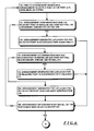
- FIGS. 6 and 7 depict the operations performed by the fine-to-coarse mesh generating arrangement in generating a coarse (“j”) level mesh from a finer (“j+1”) level mesh.
- the flow chart in FIG. 6 depicts the operations performed in connection with a triangular mesh and the flow chart in FIG. 7 depicts the operations performed in connection with a quadrangular mesh.
- the arrangement will first perform a series of steps to generate the Laplacian (equations (10) through (12)) for each of the points in the triangular finer (“j+1”) level mesh.
- the arrangement will select a point in the finer (j+1) level mesh as vertex (step 100 ) and determine whether the point is regular, that is, whether its valence “K” is six, and does not fall on a boundary, crease line or the like (step 101 ). If the arrangement makes a positive determination in step 101 , it proceeds to step 102 in which it generates the Laplacian for the point selected in step 100 in accordance with equation (11).
- step 101 determines whether the point is irregular, that is, whether its valence “K” is less than six and does not fall on a boundary, crease line or the like (step 103 ). If the arrangement makes a positive determination in step 103 , it proceeds to step 104 in which it generates the Laplacian for the point selected in step 100 in accordance with equation (12).
- step 103 the arrangement makes a negative determination in step 103 , which will be the case if the point falls on a boundary, crease line or the like, it proceeds to step 105 in which it generates the Laplacian for the point selected in step 100 in accordance with equation (10).
- step 106 the arrangement will determine whether all of the points have been selected in step 100 (step 106 ). If the arrangement makes a negative determination in step 106 , it will not have generated Laplacians for all of the points in the finer (“j+1”) level mesh, and, in that case, it will return to step 100 to select another point and perform respective steps 101 through 105 in connection therewith.
- the arrangement performs step 100 and respective steps 101 through 105 through a plurality of iterations, in each iteration selecting and generating the Laplacian for each of the points in the finer (“j+1”) level mesh.
- the arrangement will make a positive determination in step 106 , at which point it will sequence to a series of steps in which the arrangement determines the positions c j (q) for points in the finer (“j+1”) level mesh that are to be retained in the coarse (“j”) level mesh. In those operations, the arrangement will select a point in the finer (“j+1”) level mesh (step 110 ) and determine whether the point is to be retained in the coarse (“j”) level mesh (step 111 ). If the arrangement makes a negative determination in step 111 , the point is not to be retained in the coarse (“j”) level mesh.
- the arrangement will sequence to a step 112 in which it determines whether it has selected all of the points in the finer (“j+1”) level mesh. If the arrangement makes a negative determination in step 112 , it will return to step 110 to select another point in the finer (“j+1”) level mesh. On the other hand, if the arrangement makes a positive determination in step 112 , which will be the case if it has processed all of the points in the finer (“j+1”) level mesh, it will exit (step 113 ).
- the arrangement can make use of any of a number of methodologies in determining whether a point in the finer (“j+1”) level mesh will be retained in the coarse (“j”) level mesh. For example, given a suitable point indexing methodology, as will be apparent to those skilled in the art, the arrangement can determine whether a point in the finer (“j+1”) level mesh will be retained in the coarse (“j”) level mesh.
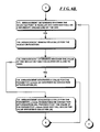
- step 111 if the arrangement makes a positive determination in that step, which will be the case if the selected point in the finer (“j+1”) level mesh will be retained, the arrangement sequences to step 115 , in which it determines whether the value of the Laplacian for the point selected in step 110 is less than “ ⁇ ” (reference inequality (24)). If the arrangement makes a positive determination in step 115 , it determines the position c j (q) of the point in the coarse (“j”) level mesh as the position c j+1 (q) of the corresponding point in the finer (“j+1”) level mesh (step 116 ). Following step 116 , the arrangement will sequence to step 112 to determine whether all of the points in the finer (“j+1”) level mesh have been processed, and, if not, return to step 110 to select another point, and, if so, exit.
- step 115 determines whether the value of the Laplacian for the point selected in step 110 is less than “ ⁇ ” (reference inequality (24)). If the arrangement makes a positive
- step 115 if the arrangement makes a negative determination in that step, it will sequence to step 117 , in which it will determine whether the point is regular, that is, whether its valence “K” is six, and does not fall on a boundary, crease line or the like. If the arrangement makes a positive determination in that step, it will generate a value for the indicator function (reference equation (18)) (step 118 ). The arrangement will then determine whether the value of the indicator function is zero or close to zero (step 119 ). If the arrangement makes a positive determination in step 119 , it will provide a value for the parameter ⁇ as described above in connection with equation (26) (step 120 ).
- step 119 it will provide a value for the parameter ⁇ as described above in connection with equation (29), provided that the value of the parameter ⁇ does not fall below the value specified in equation (26) (step 121 ).
- step 117 if the arrangement makes a negative determination in that step, it will sequence to step 122 to determine whether the point is irregular, that is, whether its valence “K” is not equal to six, and the point does not fall on a boundary, crease line or the like. If the arrangement makes a positive determination in that step, it will generate a value for the indicator function (reference equation (18)) (step 123 ). The arrangement will then determine whether the value of the indicator function is zero or close to zero (step 124 ). If the arrangement makes a positive determination in step 124 , it will provide a value for the parameter ⁇ as described above in connection with equation (27) (step 125 ).
- step 124 it will provide a value for the parameter ⁇ as described above in connection with equation (30), provided that the value of the parameter ⁇ does not fall below the value specified in equation (26) (step 126 ).
- step 122 if the arrangement makes a negative determination in that step, it will sequence to step 127 to determine whether the point falls on a boundary, crease line or the like. If the arrangement makes a positive determination in that step, it will generate a value for the indicator function (reference equation (17)) (step 128 ). The arrangement will then determine whether the value of the indicator function is zero or close to zero (step 129 ). If the arrangement makes a positive determination in step 129 , it will provide a value for the parameter ⁇ as described above in connection with equation (25) (step 130 ).
- step 129 it will provide a value for the parameter ⁇ as described above in connection with equation (28), provided that the value of the parameter ⁇ does not fall below the value specified in equation (25) (step 131 ).
- step 132 determines whether the value of the parameter ⁇ generated in the respective step was greater than “one,” and, if so, limit the maximum value of parameter ⁇ to “one” (step 133 ). Thereafter, the arrangement uses equation (23) to determine the position c j+1 (q) of the point in the coarse (“j”) level mesh (step 134 ).
- step 134 the arrangement the arrangement will sequence to step 112 to determine whether all of the points in the finer (“j+1”) level mesh have been processed, and, if not, return to step 110 to select another point, and, if so, exit.
- the flow chart in FIG. 7 depicts the operations performed in connection with a quadrangular mesh.
- the arrangement will first perform a series of steps to generate the Laplacians (equations (14) through (16)) for each of the points in the quadrilateral finer (“j+1”) level mesh. Initially, the arrangement will select a point in the finer (j+1) level mesh as vertex (step 150 ) and determine whether the point does not fall on a boundary, crease line or the like (step 151 ). If the arrangement makes a positive determination in step 151 , it proceeds to step 152 in which it generates the Laplacian for the point selected in step 150 in accordance with equations (15) and (16).
- step 151 if the arrangement makes a negative determination in step 151 , which will be the case if the point falls on a boundary, crease line or the like, it proceeds to step 153 in which it generates the Laplacian for the point selected in step 150 in accordance with equation (14).
- step 152 or 153 the arrangement will determine whether all of the points have been selected in step 150 (step 154 ). If the arrangement makes a negative determination in step 154 , it will not have generated Laplacians for all of the points in the finer (“j+1”) level mesh, and, in that case, it will return to step 150 to select another point and perform respective steps 151 through 153 in connection therewith.
- the arrangement performs step 150 and respective steps 151 through 153 through a plurality of iterations, in each iteration selecting and generating the Laplacian for each of the points in the finer (“j+1”) level mesh.
- the arrangement will make a positive determination in step 154 , at which point it will sequence to a series of steps in which the arrangement determines the positions c j (q) for respective points in the coarse (“j”) level mesh using the positions c j+1 (q) of the points in the finer (“j+1”) level mesh and the values of parameters to be generated and the Laplacians generated in steps 150 through 153 .
- the arrangement will select a point in the finer (“j+1”) level mesh (step 160 ) and determine whether the values of both Laplacians L e (k,j+1) and L f (k,j+1) generated for the point selected instep 160 are less than “ ⁇ ” (reference inequality (34)) (step 161 ). If the arrangement makes a positive determination in step 161 , it determines the position c j (q) of the point in the coarse (“j”) level mesh as the position c j+1 (q) of the same point in the finer (“j+1”) level mesh (step 162 ).
- step 162 the arrangement will sequence to step 163 to determine whether all of the points in the finer (“j+1”) level mesh have been processed, and, if not, return to step 160 to select another point. On the other hand, if the arrangement makes a positive determination in step 163 , it will exit (step 164 ).
- step 161 if the arrangement makes a negative determination in that step, it will sequence to step 165 , in which it determines whether the determine whether the point is regular, that is, whether its valence “K” is four, and does not fall on a boundary, crease line or the like. If the arrangement makes a positive determination in step 165 , it will generate a value for the indicator function (reference equation (22)) (step 166 ) and determine whether the value of the indicator function is near zero (reference inequality (35)) (step 167 ). If the arrangement makes a positive determination in step 167 , it will generate values for ⁇ 1 and ⁇ 2 as described above in connection with equations (36) (step 168 ).
- step 167 it will generate values for ⁇ 1 and ⁇ 2 as described above in connection with equations (38)–(40), in the process ensuring that the values of ⁇ 1 and ⁇ 2 are within predetermined limits ( ⁇ 4 ⁇ 1 ⁇ 1 ⁇ 2, 1 ⁇ 4 ⁇ 2 ⁇ 1) (step 169 ).
- step 165 if the arrangement makes a negative determination in that step, it will sequence to step 170 , in which it determines whether the point is irregular, that is, whether its valence “K” is other than four, and does not fall on a boundary, crease line or the like. If the arrangement makes a positive determination in step 170 , it will generate a value for the indicator function (reference equation (22)) (step 171 ) and determine whether the value of the indicator function is near zero (reference inequality (35)) (step 172 ). If the arrangement makes a positive determination in step 172 , it determine whether the valence “K” of the point is “three” (step 173 ).
- step 173 If the arrangement makes a positive determination in step 173 , it will generate values for ⁇ 1 and ⁇ 2 as described above in connection with equation (37) (step 174 ). On the other hand, if the arrangement makes a negative determination in step 173 , it will generate values for ⁇ 1 and ⁇ 2 as described above in connection with equation (36) (step 175 ). Returning to step 172 , if the arrangement makes a negative determination in step 172 , which will be the case if the value for the indicator function as generated in step 171 is not near zero, it will generate values for ⁇ 1 and ⁇ 2 as described above in connection with equations (38)–(40), in the process ensuring that the values of ⁇ 1 and ⁇ 2 are within predetermined limits
- step 176 ( - 4 K - 3 ⁇ ⁇ 1 ⁇ 1 2 , 1 4 ⁇ ⁇ 2 ⁇ 1 K - 3 ) (step 176 ).
- step 177 determines whether the point falls on a boundary, crease line or the like. If the arrangement makes a positive determination in that step, it will generate a value for the indicator function (reference equation (17)) (step 178 ). The arrangement will then determine whether the value of the indicator function is zero or near zero (reference inequality (35) above) (step 179 ). If the arrangement makes a positive determination in step 179 , it will provide a value for the parameter ⁇ as described above in connection with equation (25) (step 180 ). On the other hand, if the arrangement makes a negative determination in step 179 , it will provide a value for the parameter ⁇ as described above in connection with equation (28) (step 181 ).
- step 182 the arrangement will sequence to step 182 , in which it uses equation (33) and values for parameters ⁇ 1 and ⁇ 2 generated in the previous steps to determine the position c j+1 (q) of the point in the coarse (“j”) level mesh.
- step 163 the arrangement will sequence to step 163 to determine whether all of the points in the finer (“j+1”) level mesh have been processed, and, if not, return to step 160 to select another point, and, of so, sequence to step 164 to exit.
- the invention provides a number of advantages.
- the invention provides an arrangement for generating a coarse (“j”) level mesh representing a surface, from a finer (“j+1”) level mesh surface representation.
- the arrangement makes use of an indicator function to provide an indication as to which of several methodologies is be used at respective ones of the points in the finer (“j+1”) level mesh, including a subdivision-inverse filter methodology and a least-squares optimization methodology.
- a system in accordance with the invention can be constructed in whole or in part from special purpose hardware or a general purpose computer system, or any combination thereof, any portion of which may be controlled by a suitable program.
- Any program may in whole or in part comprise part of or be stored on the system in a conventional manner, or it may in whole or in part be provided in to the system over a network or other mechanism for transferring information in a conventional manner.
- the system may be operated and/or otherwise controlled by means of information provided by an operator using operator input elements (not shown) which may be connected directly to the system or which may transfer the information to the system over a network or other mechanism for transferring information in a conventional manner.
Landscapes
- Physics & Mathematics (AREA)
- Engineering & Computer Science (AREA)
- Computer Graphics (AREA)
- Geometry (AREA)
- Software Systems (AREA)
- General Physics & Mathematics (AREA)
- Theoretical Computer Science (AREA)
- Image Generation (AREA)
- Image Analysis (AREA)
- Image Processing (AREA)
- Measurement Of Levels Of Liquids Or Fluent Solid Materials (AREA)
Abstract
Description
and points v′q(1) 22(1) at positions cj+1(1) that are determined by
where the weighting factor a(K) is given by
Equations (1) and (2) are applied by selecting each point in the mesh at level “j” as a vertex, to provide points for the mesh at level “j+1.” Loop's surface subdivision methodology can be applied recursively to provide a mesh at any desired degree of fineness. It will be appreciated that equation (2) will provide that the point v′q(1) 22(1) that is created when the methodology is applied to point vq 21(0) as the vertex will be in the same position when the methodology is applied to point vq(k) 21(k) as the vertex.
In the edge point generation iteration, the edge points are generated and located at positions cj+1(1i) determined as follows:
In the vertex point generation iteration, the new vertex points are generated and located at positions as follows:
In terms of only points cj, that is substituting for the last term in equation (6),
where
Equation (8) would correspond to the Catmull-Clark methodology (equation (6)) with
except that, for K=3,
instead of 1/12. In terms of only points cj (compare equation (7))
where cj+1(k) is the position of the vertex v′q in the finer (“j+1) level mesh for which the Laplacian is being generated, and cj+1(k−1) and cj+1(k+1) are the positions of the neighboring points v′q(k−1) and v′q(k+1) in the fine (j+1) level mesh. In the two-dimensional case, that is, in the case of a vertex v′q other than on a boundary, crease line or the like, for a regular vertex, that is, for a vertex for which the valence “K” is equal to “six,” the Laplacian is
where the factor “⅙” reflects the valence of the vertex. Also in the two-dimensional case, for an irregular vertex, that is, for a vertex for which the valence “K” is not equal to “six,” which may be the case at, for example, edges of the mesh, the Laplacian is
where a(K) is defined in equation (3) above.
where cj+1(k) is the position of the vertex v′q for which the Laplacian is being generated in the finer (“j+1”) level mesh, and cj+1(k−1) and cj+1(k+1) are the positions of the neighboring points in the finer (j+1) level mesh. In the two-dimensional case, that is, in the case of a vertex v′q other than on a boundary, crease line or the like, two Laplacians are used, namely a Laplacian Le(k,j+1) using the position cj+1(k) of the vertex v′q and the positions of the points whose indices are in the set Ne(q,j), and a Laplacian Lf(k,j+l) using the position cj+1(k) and the positions of the vertices whose indices are in the set Nf(q,j), as follows
As will be described below, the arrangement makes use of values of both Laplacians Le(k,j+1) and Lf(k,j+1), and so both values will be generated for each vertex.
and, for the two-dimensional case
where the indices for the sums in equation (18) are in the neighborhood of the vertex for which the indicator function is being evaluated are as depicted in
for vertices for which valence “K” is not equal to “three.” For vertices for which the valence “K” does equal “three,” Lind(k,j+1) takes the form
For regular vertices, that is, for vertices for which the valence “K” equals “four,” equation (19) becomes
With this background, the indicator function i(k) for quadrilateral meshes is given by (omitting the index “j+1,” since the indicator function will always be evaluated for vertices in the fine (j+1) level mesh)
where the vertex neighborhoods for the respective sums are as shown in
c j(k)=c j+1(k)+λL(k, j+1) (23),
where λ is a parameter whose value are determined as described below and L(k,j+1) is the value of the Laplacian generated for the vertex v′q in the finer (j+1) level mesh. As noted above, not all of the vertices in the finer (“j+1”) level mesh will have corresponding vertices in the coarse (“j”) level mesh. If the value of the Laplacian L(k,j+1) generated for a vertex v′q in the finer (“j+1”) level mesh is relatively small, that is, if
|L(k,j+1)|<ε (24)
for a selected small ε, then for equation (23), the position cj(k) of the corresponding vertex vq in the coarse (“j”) level mesh can be taken as the position cj+1(k) of the vertex v′q. In that case, neither the parameter λ, nor the indicator function i(q) (equations (17) and (18)), need to be generated.
λ=−1 (25),
and
where a(K) is as defined above in connection with equation (3).
where
it will be appreciated that the factor “⅙” in equation (29) reflects the value of the valence “K,” namely, “six.”
where, for both equations (31) and (32), “K” corresponds to the valence of the irregular vertex, and a(K) is as defined in equation (3).
c j(k)=c j+1(k)+λ1 L e(k,j+1)+λ2 L f(k,j+1) (33),
where λ1 and λ2 are parameters whose values are determined as described below, and Le(k,j+1) and Lf(k,j+1) are determined as described above in connection with equations (14) through (16). In the one-dimensional case, that is, for vertices on a boundary, crease line or the like, since only Laplacian Le is used, only one parameter λ1 need be generated for use in equation (33). On the other hand for vertices that are not on a boundary, crease line, or the like, since both Laplacians Le and Lf are used, both parameters λ1 and λ2 are generated for use in equation (33). As with the triangular mesh, if the values of Le(k,j+1) and Lf(k,j+1) are relatively small, that is, if for a vertex v′q in the fine (“j+1”) level mesh
max(|L e(k,j+1)|, |L f(k,j+1)|)<ε (34)
for a selected small ε, then for equation (34), the position cj(k) of vertex vq in the coarse (“j”) level mesh can be taken as the position cj+1(k) of vertex v′q. In that case, neither the parameters λ1 and λ2, nor the indicator function i(k,j+1) (equation (22)), need to be generated.
|i(k,j+1)|≦ε·max(|L e(k,j+1)|, |L f(k,j+1)|) (35)
a subdivision-inverse filter is used in which, if the valence “K” of the vertex not equal to “three,”
and, if the valence “K” for the vertex is equal to “three,”
λ1=−8, λ2=2 (37).
On the other hand, if, for a vertex v′q, the value of the indicator function i(k,j+1) is not near zero, that is, if the condition in inequality (35) is not satisfied,
which reflect a least squares optimization. If vertex v′q is regular, that is, if the vertex's valence “K” is “four,”
On the other hand, if the vertex v′q is irregular, that is, if the vertex's valence “K” is other than “four,”
The following are approximations for equations (40) that are used in one embodiment of the arrangement:
b10 cc=−2.04583
b11 cc=−2.5284
b20 cc=1.69069
b21 cc=−1.37687 (42),
and the following are approximations for equations (41) that are used in the same embodiment:
(step 176).
Claims (16)
c j(k)=c j+1(k)+λ L(k,j+1)
c j(k)=c j+1(k)+λ L(k,j+1)
c j(k)=c j+1(k)+λ L(k,j+1)
c j(k)=c j+1(k)+λ L(k,j+1)
c j(k)=c j+1(k)+λ 1 L e(k,j+1)+λ 2 L f(k,j+1)
c j(k)=c j+1(k)+λ L(k,j+1)
c j(k)=c j+1(k)+λ L(k,j+1)
c j(k)=c j+1(k)+λ L(k,j+1)
c j(k)=c j+1(k)+λ L(k,j+1)
c j(k)=c j+1(k)+λ 1 L e(k,j+1)+λ 2 L f(k,j+1)
Priority Applications (3)
| Application Number | Priority Date | Filing Date | Title |
|---|---|---|---|
| US09/852,906 US7184039B2 (en) | 2000-05-09 | 2001-05-09 | Computer-implemented method for generating coarse level meshes for multi-resolution surface editing |
| US11/623,883 US7453457B2 (en) | 2000-05-09 | 2007-01-17 | Computer graphics using coarse level meshes |
| US12/271,963 US20090146998A1 (en) | 2000-05-09 | 2008-11-17 | Computer graphics using coarse level meshes |
Applications Claiming Priority (2)
| Application Number | Priority Date | Filing Date | Title |
|---|---|---|---|
| US20315800P | 2000-05-09 | 2000-05-09 | |
| US09/852,906 US7184039B2 (en) | 2000-05-09 | 2001-05-09 | Computer-implemented method for generating coarse level meshes for multi-resolution surface editing |
Related Child Applications (1)
| Application Number | Title | Priority Date | Filing Date |
|---|---|---|---|
| US11/623,883 Continuation US7453457B2 (en) | 2000-05-09 | 2007-01-17 | Computer graphics using coarse level meshes |
Publications (2)
| Publication Number | Publication Date |
|---|---|
| US20050276518A1 US20050276518A1 (en) | 2005-12-15 |
| US7184039B2 true US7184039B2 (en) | 2007-02-27 |
Family
ID=22752754
Family Applications (3)
| Application Number | Title | Priority Date | Filing Date |
|---|---|---|---|
| US09/852,906 Expired - Lifetime US7184039B2 (en) | 2000-05-09 | 2001-05-09 | Computer-implemented method for generating coarse level meshes for multi-resolution surface editing |
| US11/623,883 Expired - Fee Related US7453457B2 (en) | 2000-05-09 | 2007-01-17 | Computer graphics using coarse level meshes |
| US12/271,963 Abandoned US20090146998A1 (en) | 2000-05-09 | 2008-11-17 | Computer graphics using coarse level meshes |
Family Applications After (2)
| Application Number | Title | Priority Date | Filing Date |
|---|---|---|---|
| US11/623,883 Expired - Fee Related US7453457B2 (en) | 2000-05-09 | 2007-01-17 | Computer graphics using coarse level meshes |
| US12/271,963 Abandoned US20090146998A1 (en) | 2000-05-09 | 2008-11-17 | Computer graphics using coarse level meshes |
Country Status (4)
| Country | Link |
|---|---|
| US (3) | US7184039B2 (en) |
| EP (1) | EP1292920A2 (en) |
| AU (1) | AU2001264175A1 (en) |
| WO (1) | WO2002023486A2 (en) |
Cited By (3)
| Publication number | Priority date | Publication date | Assignee | Title |
|---|---|---|---|---|
| US20070176930A1 (en) * | 2000-05-09 | 2007-08-02 | Silviu Borac | Computer graphics using coarse level meshes |
| US20090002376A1 (en) * | 2007-06-29 | 2009-01-01 | Microsoft Corporation | Gradient Domain Editing of Animated Meshes |
| US12223589B2 (en) * | 2012-06-25 | 2025-02-11 | Yoldas Askan | Method of generating a smooth image from point cloud data |
Families Citing this family (3)
| Publication number | Priority date | Publication date | Assignee | Title |
|---|---|---|---|---|
| JP4468409B2 (en) * | 2007-06-11 | 2010-05-26 | 株式会社日立製作所 | Analysis mesh generator |
| US9520001B2 (en) * | 2014-01-21 | 2016-12-13 | Adobe Systems Incorporated | 3D model enhancement |
| US12530848B2 (en) * | 2022-12-27 | 2026-01-20 | POSTECH Research and Business Development Foundation | Detailed 3D object reconstruction method and apparatus using Laplacian coordinates |
Citations (4)
| Publication number | Priority date | Publication date | Assignee | Title |
|---|---|---|---|---|
| US5506947A (en) * | 1994-09-22 | 1996-04-09 | International Business Machines Corporation | Curve and surface smoothing without shrinkage |
| EP0784295A2 (en) | 1996-01-11 | 1997-07-16 | Microsoft Corporation | Mesh simplification and construction of meshes |
| US6009435A (en) * | 1997-11-21 | 1999-12-28 | International Business Machines Corporation | Progressive compression of clustered multi-resolution polygonal models |
| US6266062B1 (en) * | 1997-10-08 | 2001-07-24 | Maria-Cecilia Rivara | Longest-edge refinement and derefinement system and method for automatic mesh generation |
Family Cites Families (1)
| Publication number | Priority date | Publication date | Assignee | Title |
|---|---|---|---|---|
| US7184039B2 (en) * | 2000-05-09 | 2007-02-27 | Mental Images Gmbh | Computer-implemented method for generating coarse level meshes for multi-resolution surface editing |
-
2001
- 2001-05-09 US US09/852,906 patent/US7184039B2/en not_active Expired - Lifetime
- 2001-05-09 AU AU2001264175A patent/AU2001264175A1/en not_active Abandoned
- 2001-05-09 WO PCT/IB2001/001089 patent/WO2002023486A2/en not_active Ceased
- 2001-05-09 EP EP01938501A patent/EP1292920A2/en not_active Withdrawn
-
2007
- 2007-01-17 US US11/623,883 patent/US7453457B2/en not_active Expired - Fee Related
-
2008
- 2008-11-17 US US12/271,963 patent/US20090146998A1/en not_active Abandoned
Patent Citations (4)
| Publication number | Priority date | Publication date | Assignee | Title |
|---|---|---|---|---|
| US5506947A (en) * | 1994-09-22 | 1996-04-09 | International Business Machines Corporation | Curve and surface smoothing without shrinkage |
| EP0784295A2 (en) | 1996-01-11 | 1997-07-16 | Microsoft Corporation | Mesh simplification and construction of meshes |
| US6266062B1 (en) * | 1997-10-08 | 2001-07-24 | Maria-Cecilia Rivara | Longest-edge refinement and derefinement system and method for automatic mesh generation |
| US6009435A (en) * | 1997-11-21 | 1999-12-28 | International Business Machines Corporation | Progressive compression of clustered multi-resolution polygonal models |
Non-Patent Citations (8)
| Title |
|---|
| D. Zorin et al., "Interactive Multi-Resolution Mesh Editing" Computer Graphics Proceedings, Siggraph 97, Los Angeles, CA, Aug. 3-8, 1997, pp. 259-268. |
| Denis Zorin, Peter Schröder, Wim Sweldens, "Interactive Multiresolution Mesh Editing," Aug. 1997, Proceedings of the 24th Annual Conference on Computer Graphics and Interactive Techniques, p. 259-268. * |
| G. Taubin, "A Signal Processing Approach To Fair Surface Design" Computer Graphics Proceedings, Siggraph, Los Angeles, CA, Aug. 6, 1997, pp. 351-358. |
| J. Popovic, et al, "Progressive Simplicial Complexes" Computer Graphics Proceedings, Siggraph 97, Los Angeles, CA, Aug. 3-8, 1997, pp. 217-224. |
| M. Garland et al, "Simplifying surfaces with color and texture using quadric error metrics" Visualization 98. Proceedings Research Triangle Park, NC, U. S. A. Oct. 19-23, 1998. |
| M. Garland et al, "Surface simplification using quadric error metrics" Computer Graphics Proceedings, Siggraph 97, Proc. 24th Int'l Conf on Computer Graphics and Interactive Techniques, Los Angeles, CA, Aug. 3-8, 1997, pp. 209-216. |
| Michael Loundsbery, Tony D. DeRose, and Joe Warren "Multiresolution Analysis for Surfaces of Arbitrary Topological Type," Jan. 1997, ACM Transactions on Graphics, vol. 16, No. 1, p. 34-73. * |
| W. J. Schroder et al., "Decimation Of Triangle Meshes" Computer Graphics, vol. 26, No. 2, pp. 65-70 (Jul. 1, 1992). |
Cited By (5)
| Publication number | Priority date | Publication date | Assignee | Title |
|---|---|---|---|---|
| US20070176930A1 (en) * | 2000-05-09 | 2007-08-02 | Silviu Borac | Computer graphics using coarse level meshes |
| US7453457B2 (en) * | 2000-05-09 | 2008-11-18 | Mental Images Gmbh | Computer graphics using coarse level meshes |
| US20090002376A1 (en) * | 2007-06-29 | 2009-01-01 | Microsoft Corporation | Gradient Domain Editing of Animated Meshes |
| US7843456B2 (en) * | 2007-06-29 | 2010-11-30 | Microsoft Corporation | Gradient domain editing of animated meshes |
| US12223589B2 (en) * | 2012-06-25 | 2025-02-11 | Yoldas Askan | Method of generating a smooth image from point cloud data |
Also Published As
| Publication number | Publication date |
|---|---|
| US20090146998A1 (en) | 2009-06-11 |
| US20050276518A1 (en) | 2005-12-15 |
| US7453457B2 (en) | 2008-11-18 |
| WO2002023486A3 (en) | 2002-06-27 |
| WO2002023486A2 (en) | 2002-03-21 |
| EP1292920A2 (en) | 2003-03-19 |
| AU2001264175A1 (en) | 2002-03-26 |
| US20070176930A1 (en) | 2007-08-02 |
Similar Documents
| Publication | Publication Date | Title |
|---|---|---|
| Pauly et al. | Spectral processing of point-sampled geometry | |
| JP4012258B2 (en) | Progressive mesh adaptive subdivision method and apparatus | |
| US6285372B1 (en) | Multiresolution adaptive parameterization of surfaces | |
| Duchaineau et al. | ROAMing terrain: Real-time optimally adapting meshes | |
| JP4083238B2 (en) | Progressive mesh adaptive subdivision method and apparatus | |
| US7129942B2 (en) | System and method for performing domain decomposition for multiresolution surface analysis | |
| Haber et al. | Smooth approximation and rendering of large scattered data sets | |
| US7423641B2 (en) | Computer graphics systems and methods generating smooth feature lines for subdivision surfaces | |
| US7453457B2 (en) | Computer graphics using coarse level meshes | |
| EP0782105B1 (en) | Processing image data | |
| Mandad et al. | Isotopic approximation within a tolerance volume | |
| US20060050073A1 (en) | Tetrahedral mesh generating method and program | |
| US6693631B2 (en) | System and method for multi-resolution fairing of non-manifold models | |
| JP2837584B2 (en) | How to create terrain data | |
| Enger | Interval ray tracing—a divide and conquer strategy for realistic computer graphics | |
| US6346949B1 (en) | Three-dimensional form data processor retaining information on color boundaries of an object when thinning coordinate data | |
| Tanaka et al. | Accuracy-based sampling and reconstruction with adaptive grid for parallel hierarchical tetrahedrization | |
| Mostafavian et al. | An optimization-based mesh-generation method for image representation | |
| Garcia et al. | Approximation and processing of intensity images with discontinuity-preserving adaptive triangular meshes | |
| US20070206864A1 (en) | Method and System for Determining Compactness of an Object | |
| Liu et al. | An image interpolation method based on weighted subdivision | |
| Brown | Selective mesh refinement for interactive terrain rendering | |
| Bronsvoort | An algorithm for visible-line and visible-surface display of CSG models | |
| JP2796900B2 (en) | Image interpolation device | |
| CN121033313A (en) | Multi-view 3D reconstruction method, apparatus, equipment and storage medium |
Legal Events
| Date | Code | Title | Description |
|---|---|---|---|
| FEPP | Fee payment procedure |
Free format text: PAYOR NUMBER ASSIGNED (ORIGINAL EVENT CODE: ASPN); ENTITY STATUS OF PATENT OWNER: LARGE ENTITY |
|
| AS | Assignment |
Owner name: MENTAL IMAGES GMBH, GERMANY Free format text: MERGER;ASSIGNOR:MENTAL IMAGES G.M.B.H. & CO. KG;REEL/FRAME:017251/0320 Effective date: 20031001 |
|
| STCF | Information on status: patent grant |
Free format text: PATENTED CASE |
|
| AS | Assignment |
Owner name: MENTAL IMAGES G.M.B.H. & CO. KG, GERMANY Free format text: ASSIGNMENT OF ASSIGNORS INTEREST;ASSIGNOR:BORAC, SILVIU;REEL/FRAME:020261/0723 Effective date: 20000503 |
|
| AS | Assignment |
Owner name: MENTAL IMAGES GMBH, GERMANY Free format text: MERGER;ASSIGNOR:MENTAL IMAGES G.M.B.H. & CO. KG;REEL/FRAME:020279/0902 Effective date: 20060119 |
|
| FPAY | Fee payment |
Year of fee payment: 4 |
|
| FPAY | Fee payment |
Year of fee payment: 8 |
|
| MAFP | Maintenance fee payment |
Free format text: PAYMENT OF MAINTENANCE FEE, 12TH YEAR, LARGE ENTITY (ORIGINAL EVENT CODE: M1553) Year of fee payment: 12 |