US718221A - Indirectly-acting centrifugal regulator. - Google Patents
Indirectly-acting centrifugal regulator. Download PDFInfo
- Publication number
- US718221A US718221A US11338302A US1902113383A US718221A US 718221 A US718221 A US 718221A US 11338302 A US11338302 A US 11338302A US 1902113383 A US1902113383 A US 1902113383A US 718221 A US718221 A US 718221A
- Authority
- US
- United States
- Prior art keywords
- gear
- shaft
- belt
- friction
- pulleys
- Prior art date
- Legal status (The legal status is an assumption and is not a legal conclusion. Google has not performed a legal analysis and makes no representation as to the accuracy of the status listed.)
- Expired - Lifetime
Links
- 230000033001 locomotion Effects 0.000 description 11
- 230000001276 controlling effect Effects 0.000 description 7
- 230000008859 change Effects 0.000 description 4
- 230000004048 modification Effects 0.000 description 4
- 238000012986 modification Methods 0.000 description 4
- 230000001105 regulatory effect Effects 0.000 description 4
- 230000009471 action Effects 0.000 description 2
- 230000007246 mechanism Effects 0.000 description 2
- 238000010276 construction Methods 0.000 description 1
- 238000006073 displacement reaction Methods 0.000 description 1
Images


Classifications
-
- F—MECHANICAL ENGINEERING; LIGHTING; HEATING; WEAPONS; BLASTING
- F03—MACHINES OR ENGINES FOR LIQUIDS; WIND, SPRING, OR WEIGHT MOTORS; PRODUCING MECHANICAL POWER OR A REACTIVE PROPULSIVE THRUST, NOT OTHERWISE PROVIDED FOR
- F03B—MACHINES OR ENGINES FOR LIQUIDS
- F03B15/00—Controlling
-
- Y—GENERAL TAGGING OF NEW TECHNOLOGICAL DEVELOPMENTS; GENERAL TAGGING OF CROSS-SECTIONAL TECHNOLOGIES SPANNING OVER SEVERAL SECTIONS OF THE IPC; TECHNICAL SUBJECTS COVERED BY FORMER USPC CROSS-REFERENCE ART COLLECTIONS [XRACs] AND DIGESTS
- Y02—TECHNOLOGIES OR APPLICATIONS FOR MITIGATION OR ADAPTATION AGAINST CLIMATE CHANGE
- Y02E—REDUCTION OF GREENHOUSE GAS [GHG] EMISSIONS, RELATED TO ENERGY GENERATION, TRANSMISSION OR DISTRIBUTION
- Y02E10/00—Energy generation through renewable energy sources
- Y02E10/20—Hydro energy
-
- Y—GENERAL TAGGING OF NEW TECHNOLOGICAL DEVELOPMENTS; GENERAL TAGGING OF CROSS-SECTIONAL TECHNOLOGIES SPANNING OVER SEVERAL SECTIONS OF THE IPC; TECHNICAL SUBJECTS COVERED BY FORMER USPC CROSS-REFERENCE ART COLLECTIONS [XRACs] AND DIGESTS
- Y10—TECHNICAL SUBJECTS COVERED BY FORMER USPC
- Y10T—TECHNICAL SUBJECTS COVERED BY FORMER US CLASSIFICATION
- Y10T74/00—Machine element or mechanism
- Y10T74/19—Gearing
- Y10T74/19605—Reversing means
- Y10T74/19609—Governor control
Definitions
- the present invention relates to motordrivcn auxiliary driving-gear for regulating indirectly the controlling movement of centrifugal governors-for example, such governors as are used to cut off the Water-supply to a turbine more or less or altogether.
- the mechanism is adapted to make it possible to produce this out off in varying short time according to the needs of the special case.
- This 2o regulating-gear must not, however, be suddenly accelerated or suddenly retarded, as
- the auxiliary driving-gear is provided withv a differential gear which is turned with variable degrees of diiference in speed according to regulation from a centrifugal governor, as
- This differential gear is preferably combined with two threaded parts in such manner that, following the belt-shifting, a difference in the speed 3 5 of the revolution of the two parts takes place.
- One part makes an independent movementin one or the other direction, which movement is utilized for the regulation of the working of the motor.
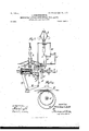
- Figure l shows one manner of carrying out the invention in side elevation, partly in section.
- Fig. 1a is a cross-section through the shafts of the auxiliary driving-gear.
- Fig. 2 is a modification in elevation, also partly in section;
- Fig. 2 a cross-section through one of the shafts of the auxiliary driving-gear, Fig. 2.
- Fig. 3 is a second modification in elevation, partly in section.
- the motor which is to be 5o regulated transmits motion to the spindle of the centrifugal regulator A and to the shaft 5 w of the auxiliary driving-gear.
- X is the controller-shaft, through which the turbine gate-valve or other controlling means is to be shifted, and gy represent the lever by which said shaft X is moved.
- the conical friction-pulley d loosely mounted on the shaft w, is revolved fromvpulley a through the medium of the two 7o 'conical friction-pulleys b and o on a countershaft w', parallel to shaft w.
- the frictionpulleys a and d of the shaft w have their smaller diameters toward each other, while the friction-disks?) and c of the parallel shaft have their greater diameters toward each other.
- the belt-rings e and f are tightly held between the conical friction-disks a and b and c and d, respectively. These belt-rings transmit the rotary motion from one set of pulleys 8o to the other by means of friction and are guided by belt-shifting forks
- the diameters of the two sets of conical pulleys are so proportioned that the number of revolutions of the loose pulley d corresponds to thatY of the shaft w when the belt-l rings e fare in lthe center of the conical pulleys a and cL'but if, on the other hand, the belt-rings are shifted by the belt-forks fr, (which are connected with each other by the 9o rods g h t' k Z) to the right orleft a change in the relative speeds of the conical pulleys a and cl takes place, and the loose pulley d will run either faster or slower than the shaft w, according to the extent and direction
- This mechanism therefore, .as regards the relative movement between d and w constitutes a differential gear with change of speed from nothing to a certain maximum limit, and this difrco ference may be made as great as desired, according to the size and taper of the pulleys.
- the relative revolution of the shaft w, with the pulley d and the hub n, is converted by means of a screw-spindle t and a sleeve o, provided with an internal thread, into a reciprocating or sliding motion suitable forcontrolling the motor to be regulated.
- the screw-spindle t turns with the shaft w, while the sleeve o is revolved through groove k' and key K by the hub nof the pulley d.
- the sleeve o is thereby displaced lengthwise on the spindle.
- a collar p, lying in a circular groove of the sleeve fu, serves to transmit the reciprocating motion to the bell-crank lever q y, to which it is secured and which controls the motor through the shaft X.
- the shifting of the belt-rings e and f between the friction-pulleys a and b or cand d is effected by a centrifugal governor A by means of the rods o 'm Z 7c 'i h g.
- the return of the belt-rings toward the central positions shown takes place from the centrifugal governor by means of the rod z, connected with the arm y of the bell-crank lever q y.
- the centrifugal governor A When the motor works too fast or too slowly, the centrifugal governor A will shift the belts from the central position to the right or to the left, whereby an increase or decrease of speed of the pulley d and hub fn. as compared-with shaft w takes place, and thereby the controlling bell-crankleveriis moved over.
- Fig. 2 shows a modification with frictiondisks and belt-rings.
- the friction-pulleys a and cl(one, (Z, loosely mounted andone,a', fast on the shaft w) are cylindrical, and the friction-disks b and c', acted upon by the friction-pulleys ct and d' through the belt-rings e and f', are fastened onto a shaft S, which is placed perpendicularly to the shaft w.
- the friction-surface of the two disks h and c lie in two horizontal planes parallel to each other, and the disk b bears on the pulley a and has a greater diameter than the disk c, lying below it.
- the two belt-forks .'12 under the influence of the centrifugal governorA, be contrarily shifted, and the rods 0l fm lL" Z k' h' g are arranged accordingly.
- the action is otherwise the same as that described with regard to Fig. l.
- the reshifting of the belts from the controlling bell-crank q y is transmitted to the centrifugal governor A by means of the rod e', connected with the arm y' of the controlling bellcrank q y.
- Fig. 3 there is shown another modification. This employs merely one belting e2, which passes around the friction-pulley a2 to contact with the friction-disk b2.
- the second friction pulley and disk (shown in Fig. 2) is replaced by a pair of conical gearing c2 d2.
- the connection-rod m2 serves to connect the centrifugal governor with the controlling bellcrank lever k2, similar as in Fig. 2.
- the action of this modified construction is the same as with that shown in Fig. 1 or Fig. 2.
- An indirect centrifugal governor comprising a controlling-lever, means to operate it, a differential gear to control said means, and levers from the governor to the gear to vary the movement of the gear to control the lever-operating means, substantially as described.
- An indirect centrifugal governor comprising a differential gear, variable friction means between the parts of the gear, a ceutrifugal governor to regulate the gear and a controlling-lever adapted to be operated by said gear, substantially as described.
- An indirect centrifugal governor comprising a dierential gear, a centrifugal governor to regulate the gear, a threaded slide adapted to be operated by the gear and a controlling-lever operated by the slide, substantially as described.
- An indirect centrifugal governor comprising a centrifugal governor, a countershaft with a threaded end, a fast and a loose pulley on the counter-shaft, a differential gear between said pulleys adapted to drive the loose by the fast pulley, means connected to the centrifugal governor to regulate the differential gear, a threaded slidable sleeve rotatable With the loose pulley and a controlling-lever connected to the slidable sleeve, substantially as described.
- An indirect centrifugal governor comprising a differential gear, a centrifugal governor to regulate the gear, a slide adapted to be operated bysaid gear and means connected to the slide whereby on its movement the differential gear will be further regulated, substantially as described.
- An indirect centrifugal governor comprising a differential gear, a centrifugal governor, a shaft and fast and loose pulleys thereon, forming part of the differential gear, a slidable threaded sleeve on the shaft, keys between the loose pulleys and sleeve to cause the sleeve to revolve with the loose pulley, a controlling-lever connected to the sleeve, levers adapted to be operated by the governor to regulate the differential gear, and a connection from said controlling-lever to the governor to further regulate said gear, substantially as described.
Landscapes
- Engineering & Computer Science (AREA)
- Chemical & Material Sciences (AREA)
- Combustion & Propulsion (AREA)
- Mechanical Engineering (AREA)
- General Engineering & Computer Science (AREA)
- Transmission Devices (AREA)
Description
No. 713,221. I i PATENTED JAN. 13, 1903.
G. SGHMITTHB'NNER. INDIRBGTLY ACTING GENTRIPUGAL REGULATOR.
APPLIATION FILED JUNE 27, 1902.
N0 MODEL. A SHBE'LS-SHEIII 1.
l @hmmm w u Penas co., vuovournafwAsmN-aros, n. c.
' No. 718,221. Y PATBNTED JAN. 1s, 190s.
' v o. SGHMITTHBNNBB..
INDIREGTLY ACTING GBNTRIFUGAL REGULATOR.
APPLIOATIUN FILED JUNE 27, 1902.
N0 MODEL. Y f 3 SHEETS-SHEET 2,
i1/.s am) n Ne rc PATENTED JAN. 13; A1903.
G. SCHMITTHENNBR. INDIRBGTLY ACTING GENTRIPUGAL REGULATOR.
"APPLIATION FILED JNE 27, 1902.
' 3 SHEETS-SHEET a.'
N0' MODEL.
/l//r/l/ll/lIl/l/l. llllllllllllllllllll` h'lllll/lllll//ll/A :as co.. PHOTOLHHU.. wgsmNGToN. D. Vc.
NiTED STATES PATENT OFFICE.
CARLOS SOHMITTHENNER, OF HElDENHElM-ON-BRENZ', GERMANY, ASSIGNOR TO J. M. VOITH, MASOHINENFABRIK, OF HEIDENHEIM-ON-BRENZ,GER-
MANY.
INDIRECTLY-ACTING CENTRIFUGAL REGULATOR.
SPECIFICATION forming part of Letters Patent N o. 718,221, dated January 13, 1903.
Application filed June 27, 1902. Serial No. 113,383. (No model.)
To @ZZ whom it may con/cern.-
Be it known that I, CARLOS SOHMIT'THEN- NER, engineer, a subject of the King of Wiirtemberg, residing in Heidenheim-on-Brenz,
Wrtemberg, Germany, (and having a postofce address at No. 27 Bahnhofstrasse, in saidHeidenheim on-Brenz,) have invented Improvements in Indirectly-Aot-ing Centrifugal Regulators, of which the following is a 1o specication.
The present invention relates to motordrivcn auxiliary driving-gear for regulating indirectly the controlling movement of centrifugal governors-for example, such governors as are used to cut off the Water-supply to a turbine more or less or altogether. The mechanism is adapted to make it possible to produce this out off in varying short time according to the needs of the special case. This 2o regulating-gear must not, however, be suddenly accelerated or suddenly retarded, as
is the case with centrifugal governors working by means of a gear changing the sense of governing motion and needing a too-long time of cutting off.
The auxiliary driving-gear is provided withv a differential gear which is turned with variable degrees of diiference in speed according to regulation from a centrifugal governor, as
3o by shifting belts between the disks or conepulleys of the differential gear. This differential gear is preferably combined with two threaded parts in such manner that, following the belt-shifting, a difference in the speed 3 5 of the revolution of the two parts takes place. One part makes an independent movementin one or the other direction, which movement is utilized for the regulation of the working of the motor.
4o Figure l shows one manner of carrying out the invention in side elevation, partly in section. Fig. 1a is a cross-section through the shafts of the auxiliary driving-gear. Fig. 2 is a modification in elevation, also partly in section; Fig. 2, a cross-section through one of the shafts of the auxiliary driving-gear, Fig. 2. Fig. 3 is a second modification in elevation, partly in section.
In all the views the motor which is to be 5o regulated transmits motion to the spindle of the centrifugal regulator A and to the shaft 5 w of the auxiliary driving-gear.
X is the controller-shaft, through which the turbine gate-valve or other controlling means is to be shifted, and gy represent the lever by which said shaft X is moved.
In the device of Fig. l myinvention is carried out by the means of belt-rings c f, carried along between conical friction-pulleys ab and c d and displaced between the pulleys by 6o means of belt-forks On the shaft w, proteoted at the bearing it by means of collars against a lengthwise displacement, there is revolubly mounted a conical friction-pulley cZ,the hub n of which is secured between collars r s against lengthwise motion. On the same shaft w the conical friction-pulley a is rmly fixed. The conical friction-pulley d, loosely mounted on the shaft w, is revolved fromvpulley a through the medium of the two 7o 'conical friction-pulleys b and o on a countershaft w', parallel to shaft w. The frictionpulleys a and d of the shaft w have their smaller diameters toward each other, while the friction-disks?) and c of the parallel shaft have their greater diameters toward each other.
The belt-rings e and f are tightly held between the conical friction-disks a and b and c and d, respectively. These belt-rings transmit the rotary motion from one set of pulleys 8o to the other by means of friction and are guided by belt-shifting forks The diameters of the two sets of conical pulleys are so proportioned that the number of revolutions of the loose pulley d corresponds to thatY of the shaft w when the belt-l rings e fare in lthe center of the conical pulleys a and cL'but if, on the other hand, the belt-rings are shifted by the belt-forks fr, (which are connected with each other by the 9o rods g h t' k Z) to the right orleft a change in the relative speeds of the conical pulleys a and cl takes place, and the loose pulley d will run either faster or slower than the shaft w, according to the extent and direction of the shifting of the belt-rings @and f. This mechanism, therefore, .as regards the relative movement between d and w constitutes a differential gear with change of speed from nothing to a certain maximum limit, and this difrco ference may be made as great as desired, according to the size and taper of the pulleys.
The relative revolution of the shaft w, with the pulley d and the hub n, is converted by means of a screw-spindle t and a sleeve o, provided with an internal thread, into a reciprocating or sliding motion suitable forcontrolling the motor to be regulated. The screw-spindle t turns with the shaft w, while the sleeve o is revolved through groove k' and key K by the hub nof the pulley d. The sleeve o is thereby displaced lengthwise on the spindle. A collar p, lying in a circular groove of the sleeve fu, serves to transmit the reciprocating motion to the bell-crank lever q y, to which it is secured and which controls the motor through the shaft X.
The shifting of the belt-rings e and f between the friction-pulleys a and b or cand d is effected by a centrifugal governor A by means of the rods o 'm Z 7c 'i h g. The return of the belt-rings toward the central positions shown takes place from the centrifugal governor by means of the rod z, connected with the arm y of the bell-crank lever q y.
When the motor works too fast or too slowly, the centrifugal governor A will shift the belts from the central position to the right or to the left, whereby an increase or decrease of speed of the pulley d and hub fn. as compared-with shaft w takes place, and thereby the controlling bell-crankleveriis moved over.
According as the change in speed is greater or less the shifting of belt and the distance which the controlling bellcrank lever is moved will be greater or less.
Fig. 2 shows a modification with frictiondisks and belt-rings. The friction-pulleys a and cl(one, (Z, loosely mounted andone,a', fast on the shaft w) are cylindrical, and the friction-disks b and c', acted upon by the friction-pulleys ct and d' through the belt-rings e and f', are fastened onto a shaft S, which is placed perpendicularly to the shaft w.
The friction-surface of the two disks h and c lie in two horizontal planes parallel to each other, and the disk b bears on the pulley a and has a greater diameter than the disk c, lying below it. In order to obtain the desired change of speed with this form of frictiondisks, it is of course necessary that the two belt-forks .'12, under the influence of the centrifugal governorA, be contrarily shifted, and the rods 0l fm lL" Z k' h' g are arranged accordingly. The action is otherwise the same as that described with regard to Fig. l. The reshifting of the belts from the controlling bell-crank q y is transmitted to the centrifugal governor A by means of the rod e', connected with the arm y' of the controlling bellcrank q y.
In Fig. 3 there is shown another modification. This employs merely one belting e2, which passes around the friction-pulley a2 to contact with the friction-disk b2. The second friction pulley and disk (shown in Fig. 2) is replaced by a pair of conical gearing c2 d2. The connection-rod m2 serves to connect the centrifugal governor with the controlling bellcrank lever k2, similar as in Fig. 2. The action of this modified construction is the same as with that shown in Fig. 1 or Fig. 2.
I claim as my inventionl. An indirect centrifugal governor comprising a controlling-lever, means to operate it, a differential gear to control said means, and levers from the governor to the gear to vary the movement of the gear to control the lever-operating means, substantially as described.
2. An indirect centrifugal governor, comprising a differential gear, variable friction means between the parts of the gear, a ceutrifugal governor to regulate the gear and a controlling-lever adapted to be operated by said gear, substantially as described.
3. An indirect centrifugal governor, comprising a dierential gear, a centrifugal governor to regulate the gear, a threaded slide adapted to be operated by the gear and a controlling-lever operated by the slide, substantially as described.
4. An indirect centrifugal governor, comprising a centrifugal governor, a countershaft with a threaded end, a fast and a loose pulley on the counter-shaft, a differential gear between said pulleys adapted to drive the loose by the fast pulley, means connected to the centrifugal governor to regulate the differential gear, a threaded slidable sleeve rotatable With the loose pulley and a controlling-lever connected to the slidable sleeve, substantially as described.
5. An indirect centrifugal governor, comprising a differential gear, a centrifugal governor to regulate the gear, a slide adapted to be operated bysaid gear and means connected to the slide whereby on its movement the differential gear will be further regulated, substantially as described.
6. An indirect centrifugal governor, comprising a differential gear, a centrifugal governor, a shaft and fast and loose pulleys thereon, forming part of the differential gear, a slidable threaded sleeve on the shaft, keys between the loose pulleys and sleeve to cause the sleeve to revolve with the loose pulley, a controlling-lever connected to the sleeve, levers adapted to be operated by the governor to regulate the differential gear, and a connection from said controlling-lever to the governor to further regulate said gear, substantially as described.
In testimony whereof I have signed my name to this specification in the presence of two subscribing witnesses.
CARLOS SCHMITTHENNER.
Witnesses ERNST ENTENMAN, WM. HAHN.
IOO
IIO
Priority Applications (1)
| Application Number | Priority Date | Filing Date | Title |
|---|---|---|---|
| US11338302A US718221A (en) | 1902-06-27 | 1902-06-27 | Indirectly-acting centrifugal regulator. |
Applications Claiming Priority (1)
| Application Number | Priority Date | Filing Date | Title |
|---|---|---|---|
| US11338302A US718221A (en) | 1902-06-27 | 1902-06-27 | Indirectly-acting centrifugal regulator. |
Publications (1)
| Publication Number | Publication Date |
|---|---|
| US718221A true US718221A (en) | 1903-01-13 |
Family
ID=2786738
Family Applications (1)
| Application Number | Title | Priority Date | Filing Date |
|---|---|---|---|
| US11338302A Expired - Lifetime US718221A (en) | 1902-06-27 | 1902-06-27 | Indirectly-acting centrifugal regulator. |
Country Status (1)
| Country | Link |
|---|---|
| US (1) | US718221A (en) |
Cited By (1)
| Publication number | Priority date | Publication date | Assignee | Title |
|---|---|---|---|---|
| US2654301A (en) * | 1946-05-23 | 1953-10-06 | Deere & Co | Draft control mechanism |
-
1902
- 1902-06-27 US US11338302A patent/US718221A/en not_active Expired - Lifetime
Cited By (1)
| Publication number | Priority date | Publication date | Assignee | Title |
|---|---|---|---|---|
| US2654301A (en) * | 1946-05-23 | 1953-10-06 | Deere & Co | Draft control mechanism |
Similar Documents
| Publication | Publication Date | Title |
|---|---|---|
| US718221A (en) | Indirectly-acting centrifugal regulator. | |
| US447447A (en) | Gearing | |
| US390216A (en) | Speed regulating device | |
| US2421873A (en) | Governor for variable pitch propeller systems | |
| US929405A (en) | Power-transmission mechanism. | |
| US345670A (en) | campbell | |
| US949265A (en) | Power-transmission device. | |
| US993982A (en) | Speed-governor. | |
| US885207A (en) | Variable-speed driving mechanism. | |
| US858754A (en) | Speed-changing mechanism. | |
| US2659245A (en) | Speed change transmission | |
| US464895A (en) | Variable transmitting mechanism | |
| US334581A (en) | Centrifugal speed-governor | |
| US2749491A (en) | Variable frequency generating means and motor control | |
| US1320768A (en) | Speed-governor | |
| US495296A (en) | Island | |
| US1057909A (en) | Speed-governor. | |
| US46778A (en) | Improvement in governors | |
| US485361A (en) | Island | |
| US712534A (en) | Governor. | |
| US555438A (en) | Speed-governor for motors | |
| US638016A (en) | Automatic governor. | |
| US823247A (en) | Composite speed-changer. | |
| US320004A (en) | Governor for steam-engines | |
| US736542A (en) | Governor. |