US718135A - Electric coffee-roaster. - Google Patents
Electric coffee-roaster. Download PDFInfo
- Publication number
- US718135A US718135A US9738102A US1902097381A US718135A US 718135 A US718135 A US 718135A US 9738102 A US9738102 A US 9738102A US 1902097381 A US1902097381 A US 1902097381A US 718135 A US718135 A US 718135A
- Authority
- US
- United States
- Prior art keywords
- heaters
- coffee
- drum
- receptacle
- contact
- Prior art date
- Legal status (The legal status is an assumption and is not a legal conclusion. Google has not performed a legal analysis and makes no representation as to the accuracy of the status listed.)
- Expired - Lifetime
Links
- 230000033001 locomotion Effects 0.000 description 7
- 230000010006 flight Effects 0.000 description 5
- 241000533293 Sesbania emerus Species 0.000 description 4
- 239000010425 asbestos Substances 0.000 description 4
- 229910052895 riebeckite Inorganic materials 0.000 description 4
- RYGMFSIKBFXOCR-UHFFFAOYSA-N Copper Chemical compound [Cu] RYGMFSIKBFXOCR-UHFFFAOYSA-N 0.000 description 3
- 229910052802 copper Inorganic materials 0.000 description 3
- 239000010949 copper Substances 0.000 description 3
- 241000239290 Araneae Species 0.000 description 2
- 241001284615 Frangula californica Species 0.000 description 2
- 235000010627 Phaseolus vulgaris Nutrition 0.000 description 2
- 244000046052 Phaseolus vulgaris Species 0.000 description 2
- 238000010276 construction Methods 0.000 description 2
- 230000001276 controlling effect Effects 0.000 description 2
- 230000003247 decreasing effect Effects 0.000 description 2
- 239000000796 flavoring agent Substances 0.000 description 2
- 235000019634 flavors Nutrition 0.000 description 2
- 239000000446 fuel Substances 0.000 description 2
- 239000011810 insulating material Substances 0.000 description 2
- 230000001473 noxious effect Effects 0.000 description 2
- 238000005192 partition Methods 0.000 description 2
- 210000002105 tongue Anatomy 0.000 description 2
- 235000004433 Simmondsia californica Nutrition 0.000 description 1
- 235000019568 aromas Nutrition 0.000 description 1
- 235000021028 berry Nutrition 0.000 description 1
- 239000004020 conductor Substances 0.000 description 1
- 238000001816 cooling Methods 0.000 description 1
- 239000003517 fume Substances 0.000 description 1
- 239000007789 gas Substances 0.000 description 1
- 239000000463 material Substances 0.000 description 1
- 239000002184 metal Substances 0.000 description 1
- 229910052751 metal Inorganic materials 0.000 description 1
- 230000002093 peripheral effect Effects 0.000 description 1
- 229910052573 porcelain Inorganic materials 0.000 description 1
- 230000001105 regulatory effect Effects 0.000 description 1
- 230000000717 retained effect Effects 0.000 description 1
- 238000005070 sampling Methods 0.000 description 1
- 230000013707 sensory perception of sound Effects 0.000 description 1
- 238000000926 separation method Methods 0.000 description 1
- 239000002699 waste material Substances 0.000 description 1
Images

Classifications
-
- F—MECHANICAL ENGINEERING; LIGHTING; HEATING; WEAPONS; BLASTING
- F26—DRYING
- F26B—DRYING SOLID MATERIALS OR OBJECTS BY REMOVING LIQUID THEREFROM
- F26B11/00—Machines or apparatus for drying solid materials or objects with movement which is non-progressive
- F26B11/02—Machines or apparatus for drying solid materials or objects with movement which is non-progressive in moving drums or other mainly-closed receptacles
- F26B11/022—Arrangements of drives, bearings, supports
Definitions
- PATENTED JAN. is, 1903.
- My invention relates to electric coffee-roasters, the object of the same being to provide novel means whereby electric heaters may be employed in connection with a rotary drum or receptacle containing the coffee, so that contact between the coffee and said heaters is avoided.
- a further object of the invention is to provide novel means for applying electric heaters in connection with a rotary coffee-containing drum or receptacle, which avoids the necessity for passing the noxious fumes of combustible fuel therethrough.
- a further object of the invention is to provide novel means for connecting up the various heaters in the electric circuit from the generator, whereby one or more of the same may be cut in or out of the circuit for regulating the degree or intensity of the heat applied.
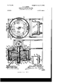
- Figure 1 is an end View of an electric coffee-roaster constructed in accordance with myinvention.
- Fig. 2 is a top plan View of the same.
- Fig. 3 is a vertical longitudinal section on the line 3 3 of Fig. 2.
- Fig. 4 is a vertical transverse section on the line 4 4 of Fig. 2.
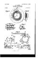
- Fig. 5 is an end view of one of the heads of the rotary drum.
- Fig. 6 is a detail sectional view of the same.
- Fig. 7 is a view showing, partly in section and partly in elevation, a set of three heaters.
- Fig. 8 is a detail cross-sectional View of one of the heaters, and
- Fig. 9 is a diagrammatic view showing the circuit connections.
- the main frame of the machine may be of any suitable form and construction. Mounted therein is a rotary drum or receptacle 1, in which the coffee is roasted, the same being adjustably secured to a horizontal shaft 2,
- the drum 1 has a cylindrical metallic wall 10 and a circular metallic head 11 at one end, these two parts being connect ed to each other, as clearly shown.
- the end of said drum opposite the head 11 is open, but is normally covered by a face-plate 12, secured to or forming part of the main frame.
- the upper end of the face-plate 12 has an opening 13 therein, communicating with the interior of the drum 1 and having leading thereinto a hopper 14 for supplying coffee to the machine.
- the opening 13 is adapted to be closed when the device is in operation by a sliding gate or valve 15.
- Adjacent to the lower end of the face-plate 12 the same is provided with a discharge-opening 16, by means of which the coffee after it has been roasted may be removed from the machine, the said opening being normally closed while the device is in operation by a hinged gate or door 17.
- An opening in the face-plate 12, closed by the flap or valve 18, may also be provided for sampling the coffee under treatment.
- This car is provided with a foraminous bottom 20, having a passage 21 beneath the same, provided with a spout or nozzle 22, by means of which the same may be connected with a suctionfan or other exhausting device for drawing air through the mass of coffee on the bottom 20, and thereby facilitating the cooling of the same.
- the open end of the drum 1 is braced and supported by means of a spider 23, the arms of which are connected at their inner ends to a hub or sleeve 24, embracing and adjustably secured to the shaft 2, and the outer ends of which are secured to a ring 25, parallel to the head 11 of the drum and secured to the cylindrical wall thereof.
- the head 11 and the cylindrical wall 10 of the drum 1 are both covered by a layer 26 of asbestos or other like heat-non-conducting material, and said layer of asbestos is itself covered by a cylindrical copper or other metallic sheet 27, extending around the cylindrical wall 10, and a circular copper or other metallic disk 28 outside the head 11.
- the copper sheet 27 and disk 28 are provided for the purpose of protecting the layer 26 of asbestos which surrounds the body of the drum and for the purpose of improving the appearance of the device as a whole.
- a foraminous diaphragm or partition 29 Located within the drum 1, parallel to the cylindrical wall thereof, is a foraminous diaphragm or partition 29, the same being constructed of perforated sheet metal, wirenetting, or other like material.
- This partition is secured at one end to the head 11 of the drum 1 and at the other end to an annular lip or flange 30 on the ring 25.
- the same forms within the drum 1 a central cylindrical receptacle 31, in which the coffee is roasted, and a surrounding annular chamber 32, in which the electric heaters are located and from which the heat is transmitted through the foraminous diaphragm 29 to the coffee within the receptacle 31.
- spiral flights or ribs 33 34 Located within the receptacle 31 are the spiral flights or ribs 33 34, designed for the purpose of agitating and keeping in movement from end to end of the receptacle the coffee contained therein.
- the outer edge of the spiral flight or rib 33 lies in contact with the inner surface of the foraminous diaphragm 29, whereas the outer edge of the flight or rib 34 is removed from the inner surface of the foraminous diaphragm 29 bya distance equal to the width of the flight 33. A passage is thereby produced outside the flight 34, between itand the diaphragm 29.
- the outer end of the shaft 2 is provided with screw-threads 39, upon which fits a nut 40, abutting against the bearing 41 of said shaft.
- This nut has extending through it, so as to engage the threads 39 on the shaft 2, a looking or set screw 42.
- the set-screw 42 By loosening the set-screw 42 the nut 41 may be turned so as to draw the shaft 2outwardly and move with said shaft the drum 1, so as to bring the ribs 37 and 38 on the ring 25 into close contact with the ribs 35 and 36 on the face-plate 12.
- the set screw 42 is screwed inwardly into engagement with the threads 39 and the further movement of the nut in either directlon is prevented. The parts will thereby be locked in position without danger of accidental separation.
- the electric heaters are located within the annular chamber 32, surrounding the foraminous diaphragm 29.
- This chamber is completely closed 011 all sides except that covered by the diaphragm 29, so that the air heated therein must necessarily pass therefrom through the openings in the diaphragm 29 to the interior of the receptacle 31, in which the cofiee is roasted.
- These heaters are arranged in sets at various points around in the chamber 32, the members of each set being designated by the reference-numerals 43 44 45. Four sets of heaters have been illustrated and three heaters have been shown in each set; but it is obvious that the number of sets may be varied and the number of heaters in each set may be increased or decreased.
- Each of said heaters consists of a hollow cylindrical spool 46, having a spiral groove 47 on its outer surface, around which the heating-coil 48 is passed and in which said coil is seated.
- Each of said spools has a metallic core or stifiening-rod 49, extending therethrough,.
- each of the spools 46 serves to stiffen and strengthen said spools, and in the event of the breakage of the porcelain of which said spools are made serve to prevent the broken parts thereof from falling away.
- the heating-coils are thereby prevented from falling down and short-circuiting through the other coils.
- each set of heaters is connected through the wire 66 with the outer ring 56.
- the heater 44 of each set of heaters is connected through the wire 67 with the contact-ring 57.
- the heater 45 of each set of heaters is connected through the wire 68 with the contact-ring 58, and all of the heaters of each set are connected through the wire 69 with the contact-ring 59. It will thus be seen that the heaters 43 of each set are connected up in multiple, as well as the heaters 44 of each set and the heaters 45 of each set.
- a switchboard or controller comprising a pivoted switch-arm 70, having a segmental contact-strip or bridge-piece 71 thereon, and the contacts 72 73 74, designed to be engaged by the strip 71. Stops 75 76 limit the swinging movement of the switch-arm 70in opposite directions.
- the contact 72 is connected through the wire 77 with the brush 61.
- the contact 73 is connected through the wire 78 with the brush 62, and the contact 74 is connected through the wire 79 with the brush 63.
- the brush 64 is connected through the wire 80 with the common return-wire 81 of the sys tem.
- the switch arm or lever 70 is connected with the generator 82 or other source of electrical supply by way of the wires 83, 84, and 85, the wires 84 and 85 having interposed between them an ordinary switch or cut-out 86.
- the motor 9 is supplied from the generator 82 through the wires 87, 88, and 89, the wire 89 being connected with the general return-wire 81. Between the wires 87 and 88 is interposed an ordinary switch or cut-out 90. In the return-wire 81 is interposed an ordinary switch or cut-out 91.
- the motor 9 and the heaters are supplied from a common source of electrical energy.
- the connections between the generator 82 and both the motor and heaters may be cut on or off by the switch 91.
- the supply to the heaters through the switch-arm 70 may be cut on or off independently of that to the motor 9 by means of the switch 86, and the supply to the motor 9 may be cut on or off independently of that to the heaters through the switch-arm 70 by means of the switch 90.
- ⁇ Vhen a high degree of heat is desired in the roaster, all of the heaters 43, 44, and 45 of each set will be thrown into operation.
- Said contact-strip 71 will then be in engagement with the contact 72 alone, as illustrated in Fig. 9 of the drawings.
- the circuit through the apparatus will then be as follows: Generator 82, wires 83 and 84, switch 86, wire 85, switch-arm 70, contact-strip 71, contact 72, Wire 77, brush 61, contact-ring 56, wire 66 of each set of heaters, heater 43 of each set, wire 69 of each set of heaters, contact-ring 59, brush 64, wires 80 and 81, and switch 91, back to the generator. It will thus be seen that a single heater 43 of each set of heaters is now in operation. By a simple manipulation of the switch-arm or lever 70, therefore, one or more of the heaters of each set may be cut into or out of the circuit and the heat generated within the roaster thereby increased or decreased.
- the sliding gate or valve 15 is opened, and coffee is introduced to the interior of the receptacle 31 through the hopper l4 and the opening 13 in the-face plate 12.
- the gate or valve 15 is closed,and the current is turned on to the motor 9 and one or more of the heaters. This is effected by closing the switch 90 between the wires '87 and 88, leading to the motor and by moving the switch-arm 70 so as to bring about the engagement of the contact-strip 71 with one or more of the contacts 72, 73, and 74.
- the motor 9 is energized, the armature-shaft 8 thereof is rotated, and the motion of said shaft is transmitted through the gearing described.
- the gate or door 17 on the face-plate 12 is opened and the contents of the receptacle 31 are discharged through the opening in said face-plate into the caror receptacle 19.
- the coffee may be suitably cooled by suction applied to the nozzle 2:2 and the same conveyed to any suitable point.
- a rotary drum having a receptacle therein in which the coffee is roasted, a separate chamber outside said receptacle but communicating therewith, and an electric heater carried by said drum and located in said chamber.
- a rotary drum having a foraminous diaphragm therein dividing the same up into a receptacle in which the coffee is roasted and a separate chamber, and electric heaters mounted in said chamber.
- a rotary cylindrical drum having a cylindrical foraminous diaphragm therein dividing the same up into a receptacle in which the coffee is roasted and an annular chamber surrounding said receptacle, and electric heaters carried by said drum and located in said chamber.
- a rotary cylindrical drum having a cylindrical foraminous diaphragm therein dividing the same up into a receptacle in which the coffee is roasted and an annular chamber surrounding said receptacle, electric heaters carried by said drum and located within said chamber, and spirally-arranged ribs or flights within said receptacle.
- a rotary cylindrical drum having a cylindrical foraminous diaphragm therein dividing the same up into a receptacle in which the coffee is roasted and an annular chamber surrounding said receptacle, electric heaters carried by said drum and located within said chamber, and a plurality of spirally arranged oppositely extending flights or ribs located within said receptacle,
- a rotary drum having one end open and the other end closed, and having an imperforate cylindrical wall, a cylindrical foraminous diaphragm,dividingsaid drum into a receptacle in which the coffee is roasted, and an annular chamber surrounding the same, electric heaters carried by said drum and located within said chamber, a fixed face-plate opposite the open end of said drum having an opening therein communicating with said receptacle, a hopper leading to said opening, and a gate or valve controlling the passage through said opening.
- a rotary shaft a drum secured thereto and comprising a cylindrical imperforate peripheral wall, an imperforate disk secured thereto and constituting one head, a ring connected to the opposite end of said cylindrical wall, a spider connecting said ring with said shaft, and a cylindrical foraminous diaphragm dividing said drum into a receptacle in which the coffee is roasted, and an annular chamber surrounding the same, electric heaters carried by said drum and located in said chamber, a fixed face-plate opposite the open end of said drum having an opening therein communicating with said receptacle, a hopper leading to said opening, and a gate or valve controlling the passage through said opening.
- a coffee-roaster a rotary shaft, a drum secured thereto, rotated thereby and having one end open, a cylindrical foraminous diaphragm dividing said drum into a receptacle in which the coffee is roasted, and into an annular chamber surrounding the same, electric heaters carried by said drum and located in said chamber, a fixed face-plate opposite the open end of said drum having an opening therein communicating with said receptacle and through which the coffee to be roasted is delivered to said receptacle, means for closing said opening, annular bearing-ribs on the inner surface of said face-plate, similar bearing-ribs cooperating therewith on the adjacent face of said drum, and means for adjusting said drum longitudinally to bring about close, contact between said bearing-ribs.
Landscapes
- Engineering & Computer Science (AREA)
- Mechanical Engineering (AREA)
- General Engineering & Computer Science (AREA)
- Baking, Grill, Roasting (AREA)
Description
No. 718,135 PATENTED JAN. 13, 1903. G. C. LESTER.
ELECTRIC COFFEE ROASTER.
- APPLICATION IIi-BD MAR. 8, 1902.
I0 IODEL. 3 SHEETS-SHEET 1,
W eozyealwie r Mom's Pnzns cc. moroumou wnsmuarom D. c.
No. 718,135. PATENTED JAN. is, 1903.
' G. c. LESTER.
ELECTRIC GOPFEE ROASTER. APPLICATION mum HA3. 8, 1902.
10 10mm. 3 sums-sums.
anew? TM: nonms Pcrzns co, PuoTo-LlTrgQ. WASHINGTON b. c.
No. 718,135. PATENTED JAN. 13, 1903 G. G. LESTER.
ELECTRIC COFFEE ROASTER.
APPLICATION FILED MAR. B, 1902.
I0 IODEL.
UNTTnn STATES PATENT OFFICE.
GEORGE O. LESTER, OF NEW YORK, N. Y.
ELECTRIC COFFEE-ROASTER.
IZPECIFIGATION forming part of Letters Patent No. 718,135, dated January 13, 1903.
Application filed March 8, 1902. Serial No. 97,381. (No model.)
To aZZ whom it may concern:
Be it known that I, GEORGE O. LESTER, a citizen of the United States, residing at New York, in the county of New York and State of New York, have invented new and useful Improvements in Electric Coffee-Roasters, of which the following is a specification.
My invention relates to electric coffee-roasters, the object of the same being to provide novel means whereby electric heaters may be employed in connection with a rotary drum or receptacle containing the coffee, so that contact between the coffee and said heaters is avoided.
A further object of the invention is to provide novel means for applying electric heaters in connection with a rotary coffee-containing drum or receptacle, which avoids the necessity for passing the noxious fumes of combustible fuel therethrough.
A further object of the invention is to provide novel means for connecting up the various heaters in the electric circuit from the generator, whereby one or more of the same may be cut in or out of the circuit for regulating the degree or intensity of the heat applied.
Other objects and advantages of the invention will hereinafter appear, and the novel features thereof will be set forth in the claims.
In the drawings forming part of this specification, Figure 1 is an end View of an electric coffee-roaster constructed in accordance with myinvention. Fig. 2 is a top plan View of the same. Fig. 3 is a vertical longitudinal section on the line 3 3 of Fig. 2. Fig. 4 is a vertical transverse section on the line 4 4 of Fig. 2. Fig. 5 is an end view of one of the heads of the rotary drum. Fig. 6 is a detail sectional view of the same. Fig. 7 is a view showing, partly in section and partly in elevation, a set of three heaters. Fig. 8 is a detail cross-sectional View of one of the heaters, and Fig. 9 is a diagrammatic view showing the circuit connections.
Like reference-numerals indicate like parts in the difierent views.
The main frame of the machine may be of any suitable form and construction. Mounted therein is a rotary drum or receptacle 1, in which the coffee is roasted, the same being adjustably secured to a horizontal shaft 2,
having suitable bearings in the main frame and provided with a gear 3 on one end. The gear 3 meshes with the pinion 4 on a countershaft 5, carrying a bevel-gear 6, which meshes with a pinion 7 on the armature-shaft S of an electric motor 9. The said motor 9 and the connections between the same and the gear 3 are suitably supported on the main frame of the machine. The drum 1 has a cylindrical metallic wall 10 and a circular metallic head 11 at one end, these two parts being connect ed to each other, as clearly shown. The end of said drum opposite the head 11 is open, but is normally covered bya face-plate 12, secured to or forming part of the main frame. The upper end of the face-plate 12 has an opening 13 therein, communicating with the interior of the drum 1 and having leading thereinto a hopper 14 for supplying coffee to the machine. The opening 13 is adapted to be closed when the device is in operation by a sliding gate or valve 15. Adjacent to the lower end of the face-plate 12 the same is provided with a discharge-opening 16, by means of which the coffee after it has been roasted may be removed from the machine, the said opening being normally closed while the device is in operation by a hinged gate or door 17. An opening in the face-plate 12, closed by the flap or valve 18, may also be provided for sampling the coffee under treatment. Beneath the discharge-opening 16 I prefer to employ a car 19 for receiving the coffee from the drum 1 and for the convenient delivery of the same to any suitable point. This car is provided with a foraminous bottom 20, having a passage 21 beneath the same, provided with a spout or nozzle 22, by means of which the same may be connected with a suctionfan or other exhausting device for drawing air through the mass of coffee on the bottom 20, and thereby facilitating the cooling of the same.
The open end of the drum 1 is braced and supported by means of a spider 23, the arms of which are connected at their inner ends to a hub or sleeve 24, embracing and adjustably secured to the shaft 2, and the outer ends of which are secured to a ring 25, parallel to the head 11 of the drum and secured to the cylindrical wall thereof. The head 11 and the cylindrical wall 10 of the drum 1 are both covered by a layer 26 of asbestos or other like heat-non-conducting material, and said layer of asbestos is itself covered by a cylindrical copper or other metallic sheet 27, extending around the cylindrical wall 10, and a circular copper or other metallic disk 28 outside the head 11. The copper sheet 27 and disk 28 are provided for the purpose of protecting the layer 26 of asbestos which surrounds the body of the drum and for the purpose of improving the appearance of the device as a whole.
Located within the drum 1, parallel to the cylindrical wall thereof, is a foraminous diaphragm or partition 29, the same being constructed of perforated sheet metal, wirenetting, or other like material. This partition is secured at one end to the head 11 of the drum 1 and at the other end to an annular lip or flange 30 on the ring 25. The same forms within the drum 1 a central cylindrical receptacle 31, in which the coffee is roasted, and a surrounding annular chamber 32, in which the electric heaters are located and from which the heat is transmitted through the foraminous diaphragm 29 to the coffee within the receptacle 31. Located within the receptacle 31 are the spiral flights or ribs 33 34, designed for the purpose of agitating and keeping in movement from end to end of the receptacle the coffee contained therein. The outer edge of the spiral flight or rib 33 lies in contact with the inner surface of the foraminous diaphragm 29, whereas the outer edge of the flight or rib 34 is removed from the inner surface of the foraminous diaphragm 29 bya distance equal to the width of the flight 33. A passage is thereby produced outside the flight 34, between itand the diaphragm 29.
To provide closed joints between the rotary drum 1 and the fixed face-plate 1.2 and prevent any of the coffee beans or berries in the receptacle 31 from escaping from the machine or from gaining access to the bearing parts, I provide on the inner surface of the face-plate 12 two annular ribs or bearingsurfaces 35 36 and form on the outer surface of the ring 25 two outwardly-projecting annular ribs or bearing-surfaces 37 38, which cooperate with the annular ribs 35 and 36. The parts being adjusted so that these ribs lie in close contact with each other, the escape of the coffee-berries from the receptacle 31 in which they are contained is rendered impossible. If, however, from wear or from any other cause the ribs 35 and 37 and 36 and 38 should become loose or separated from each other, they may be readily tightened by the means now to be described.
The outer end of the shaft 2 is provided with screw-threads 39, upon which fits a nut 40, abutting against the bearing 41 of said shaft. This nut has extending through it, so as to engage the threads 39 on the shaft 2, a looking or set screw 42. By loosening the set-screw 42 the nut 41 may be turned so as to draw the shaft 2outwardly and move with said shaft the drum 1, so as to bring the ribs 37 and 38 on the ring 25 into close contact with the ribs 35 and 36 on the face-plate 12. When the proper movement of the shaft 2 and the parts connected therewith has been effected, the set screw 42 is screwed inwardly into engagement with the threads 39 and the further movement of the nut in either directlon is prevented. The parts will thereby be locked in position without danger of accidental separation.
As heretofore stated, the electric heaters are located within the annular chamber 32, surrounding the foraminous diaphragm 29. This chamber, it will be noted, is completely closed 011 all sides except that covered by the diaphragm 29, so that the air heated therein must necessarily pass therefrom through the openings in the diaphragm 29 to the interior of the receptacle 31, in which the cofiee is roasted. These heaters are arranged in sets at various points around in the chamber 32, the members of each set being designated by the reference-numerals 43 44 45. Four sets of heaters have been illustrated and three heaters have been shown in each set; but it is obvious that the number of sets may be varied and the number of heaters in each set may be increased or decreased. Each of said heaters consists of a hollow cylindrical spool 46, having a spiral groove 47 on its outer surface, around which the heating-coil 48 is passed and in which said coil is seated. Each of said spools has a metallic core or stifiening-rod 49, extending therethrough,.
and is provided with rectangular heads 50. The said heads 50 are rabbeted, as shown at 51 to provide overlapping lips or flanges 52. When the heaters are assembled within the annular chamber 32, the same are supported upon recessed blocks or standards 53, secured to base-plates 54, attached to the inner cylindrical wall 10 of the drum 1. The said heaters are heldin placeupon the blocks or standards 53 by means of screws or pins 55, which extend through the spools 46, as
clearly shown in Fig. 8 of the drawings.
When in place, the flanges 52 on the heads 50 of the adjacent heaters overlap each other, and the same are thereby secured in place without danger of accidental derangement. The metallic core 49 in each of the spools 46 serves to stiffen and strengthen said spools, and in the event of the breakage of the porcelain of which said spools are made serve to prevent the broken parts thereof from falling away. The heating-coils are thereby prevented from falling down and short-circuiting through the other coils.
To provide means for supplying current to the various heaters arranged in the annular chamber 32, I arrange upon the outside of the metallic disk 28, which covers the sheet 26 of asbestos on the outside of the head 11 of the drum 1, a series of contact-rings 56 57 58 59. These contact-rings are mounted upon an annular band 60 of insulating material, se-
cured to the disk 28. Cooperating respectively with the contact-rings 56 57 58 59 are the brushes 61 62 63 64, carried by a hanger arm or support 65. The heater 43 of each set of heaters is connected through the wire 66 with the outer ring 56. The heater 44 of each set of heaters is connected through the wire 67 with the contact-ring 57. The heater 45 of each set of heaters is connected through the wire 68 with the contact-ring 58, and all of the heaters of each set are connected through the wire 69 with the contact-ring 59. It will thus be seen that the heaters 43 of each set are connected up in multiple, as well as the heaters 44 of each set and the heaters 45 of each set. Coiiperating with these parts is a switchboard or controller comprising a pivoted switch-arm 70, having a segmental contact-strip or bridge-piece 71 thereon, and the contacts 72 73 74, designed to be engaged by the strip 71. Stops 75 76 limit the swinging movement of the switch-arm 70in opposite directions. The contact 72 is connected through the wire 77 with the brush 61. The contact 73 is connected through the wire 78 with the brush 62, and the contact 74 is connected through the wire 79 with the brush 63. The brush 64 is connected through the wire 80 with the common return-wire 81 of the sys tem. The switch arm or lever 70 is connected with the generator 82 or other source of electrical supply by way of the wires 83, 84, and 85, the wires 84 and 85 having interposed between them an ordinary switch or cut-out 86. The motor 9 is supplied from the generator 82 through the wires 87, 88, and 89, the wire 89 being connected with the general return-wire 81. Between the wires 87 and 88 is interposed an ordinary switch or cut-out 90. In the return-wire 81 is interposed an ordinary switch or cut-out 91.
By the construction just described it will be seen that the motor 9 and the heaters are supplied from a common source of electrical energy. The connections between the generator 82 and both the motor and heaters may be cut on or off by the switch 91. The supply to the heaters through the switch-arm 70 may be cut on or off independently of that to the motor 9 by means of the switch 86, and the supply to the motor 9 may be cut on or off independently of that to the heaters through the switch-arm 70 by means of the switch 90. \Vhen a high degree of heat is desired in the roaster, all of the heaters 43, 44, and 45 of each set will be thrown into operation. This may be effected by moving the switch-arm 70 to its extreme position to the right, in which case the contact-strip 70 will be brought into engagement with all of the contacts 72, 73, and 74. The flow of current from the generator will then be over the following path: wires 83 and 84, switch 86, wire 85, switch-arm 70, contact-strip 71, contacts 72, 73, and 74, wires 77, 78, and 79, brushes 61, 62, and 63, contact- rings 56, 57, and 58, wires 66, 67, and 68 of each set of heaters, heaters 43, 44, and 45 of each set, wires 69 of each set of heaters, contact-ring 59, brush 64, wires 80 and 81, and switch 91. It will thus be seen that current is supplied to each of the heaters of each set and that the highest degree of heat which the heaters are capable of supplying will be generated. If a lower degree of heat be desired, the switch-arm 70 will be moved to the left, so as to disconnect the contact-strip 71 from the contact 74. The wire 79, brush 63, contactring 58, wire 68 of each set of heaters, and the heater 45 of each set will be thrown out of the circuit above traced, and the heaters 43 and 44 of each set of heaters will alone be in operation. If a still lower degree of heat be desired, the switch-arm 70 will be moved still farther to the left, disconnecting the contact-strip 71 from the contacts 73 and 74. Said contact-strip 71 will then be in engagement with the contact 72 alone, as illustrated in Fig. 9 of the drawings. The circuit through the apparatus will then be as follows: Generator 82, wires 83 and 84, switch 86, wire 85, switch-arm 70, contact-strip 71, contact 72, Wire 77, brush 61, contact-ring 56, wire 66 of each set of heaters, heater 43 of each set, wire 69 of each set of heaters, contact-ring 59, brush 64, wires 80 and 81, and switch 91, back to the generator. It will thus be seen thata single heater 43 of each set of heaters is now in operation. By a simple manipulation of the switch-arm or lever 70, therefore, one or more of the heaters of each set may be cut into or out of the circuit and the heat generated within the roaster thereby increased or decreased.
In the operation of my roaster the sliding gate or valve 15 is opened, and coffee is introduced to the interior of the receptacle 31 through the hopper l4 and the opening 13 in the-face plate 12. When asufficient quantity of coffee has been thus introduced into the machine,the gate or valve 15 is closed,and the current is turned on to the motor 9 and one or more of the heaters. This is effected by closing the switch 90 between the wires '87 and 88, leading to the motor and by moving the switch-arm 70 so as to bring about the engagement of the contact-strip 71 with one or more of the contacts 72, 73, and 74. When the motor 9 is energized, the armature-shaft 8 thereof is rotated, and the motion of said shaft is transmitted through the gearing described. to the shaft 2, to which the drum 1 is secured. The said drum is thereby rotated and the coffee within the receptacle 31 is kept in motion and has a longitudinal motion imparted to it by the spiral flights or ribs 33 and 34. At the same time one or more of the heaters 43, 44, and 45 of each set is thrown into operation, and the air within the annular chamber 32 is raised to the requisite degree of heat for roasting. This air passes from the chamber 32 into the receptacle 31 through the foraminous diaphragm 29 and acts upon the coffee contained within said receptacle to roast or parch the same. As the heaters 43, 44, and 45 are located in the chamber 32, which is separate from the receptacle 31, in which the coffee itself in located, it will be observed that there can be no direct contact between the coffee-beans and the heaters, which would serve to spot or unequally heat the same. This is an objection to prior apparatus which my invention overcomes. Furthermore,as the coffee isroasted by means other than the cumbustion of suitable fuel, there are no noxious gases to come in contact with the coffee-bean, and thereby deteriorate or contaminate the flavor or aroma thereof. Furthermore, as the coffee is roasted in a chamber which is closed on all sides there is no opportunity for the escape of vapors or aroma from the coffee, which are in other forms of apparatus with which I am familiar allowed to go to waste. In other words, all the vapors, flavors, and aromas which are contained in the original green coffee-bean are retained in the same after the coffee has been roasted. No artificial moistening of the roasted bean is necessary, as none of the original moisture contained therein is driven off. At such times as may be desired the coffee under treatment may be tested by withdrawing a portion of the same contained in the re-' ceptacle 31 through the opening in the faceplate 12, which is closed by the cap or cover 18. After the bean has been subjected to the roasting action of the heaters 43, 4:45, and 4:5 for a suitable period the gate or door 17 on the face-plate 12 is opened and the contents of the receptacle 31 are discharged through the opening in said face-plate into the caror receptacle 19. In this car the coffee may be suitably cooled by suction applied to the nozzle 2:2 and the same conveyed to any suitable point.
Having now described my invention, what I claim as new, and desire to secure by Letters Patent, is
1. In a coffee-roaster, a rotary drum having a receptacle therein in which the coffee is roasted, a separate chamber outside said receptacle but communicating therewith, and an electric heater carried by said drum and located in said chamber.
2. In a coffee-roaster, a rotary drum having a foraminous diaphragm therein dividing the same up into a receptacle in which the coffee is roasted and a separate chamber, and electric heaters mounted in said chamber.
3. In a coffee-roaster, a rotary cylindrical drum having a cylindrical foraminous diaphragm therein dividing the same up into a receptacle in which the coffee is roasted and an annular chamber surrounding said receptacle, and electric heaters carried by said drum and located in said chamber.
4. In a coffee-roaster, a rotary cylindrical drum having a cylindrical foraminous diaphragm therein dividing the same up into a receptacle in which the coffee is roasted and an annular chamber surrounding said receptacle, electric heaters carried by said drum and located within said chamber, and spirally-arranged ribs or flights within said receptacle.
5. In a coffee-roaster, a rotary cylindrical drum having a cylindrical foraminous diaphragm therein dividing the same up into a receptacle in which the coffee is roasted and an annular chamber surrounding said receptacle, electric heaters carried by said drum and located within said chamber, and a plurality of spirally arranged oppositely extending flights or ribs located within said receptacle,
-one of said flights or ribs having its outer edge in contact with said diaphragm, and the other located within the first and a short distance from the inner surface of said diaphragm.
6. In a coffee-roaster, a rotary drum having one end open and the other end closed, and having an imperforate cylindrical wall, a cylindrical foraminous diaphragm,dividingsaid drum into a receptacle in which the coffee is roasted, and an annular chamber surrounding the same, electric heaters carried by said drum and located within said chamber, a fixed face-plate opposite the open end of said drum having an opening therein communicating with said receptacle, a hopper leading to said opening, and a gate or valve controlling the passage through said opening.
7. In acoffee-roaster, a rotary shaft, a drum secured thereto and comprising a cylindrical imperforate peripheral wall, an imperforate disk secured thereto and constituting one head, a ring connected to the opposite end of said cylindrical wall, a spider connecting said ring with said shaft, and a cylindrical foraminous diaphragm dividing said drum into a receptacle in which the coffee is roasted, and an annular chamber surrounding the same, electric heaters carried by said drum and located in said chamber, a fixed face-plate opposite the open end of said drum having an opening therein communicating with said receptacle, a hopper leading to said opening, and a gate or valve controlling the passage through said opening.
8. In a coffee-roaster, a rotary shaft, a drum secured thereto, rotated thereby and having one end open, a cylindrical foraminous diaphragm dividing said drum into a receptacle in which the coffee is roasted, and into an annular chamber surrounding the same, electric heaters carried by said drum and located in said chamber, a fixed face-plate opposite the open end of said drum having an opening therein communicating with said receptacle and through which the coffee to be roasted is delivered to said receptacle, means for closing said opening, annular bearing-ribs on the inner surface of said face-plate, similar bearing-ribs cooperating therewith on the adjacent face of said drum, and means for adjusting said drum longitudinally to bring about close, contact between said bearing-ribs.
9. Inacoffee-roaster, arotar shaft, adrum secured thereto, rotated there y and having one end open, a cylindrical foraminous diaphragm dividing said drum into a receptacle in which the coffee is roasted, and into an annular chamber surrounding the same, electric heaters carried by said drum and located in said chamber, a fixed face-plate opposite the open end of said drum having an opening therein communicating with said receptacle and through which the coffee to be roasted is delivered to said receptacle, means for closing said opening, annular bearing-ribs on the inner surface of said plate, similar bearingribs cooperating therewith on the adjacent face of said drum, a nutbn the screw-thread ed end of said rotary shaft adapted to engage one of the hearings in which said shaft is mounted, for moving said shaft and the drum carried thereby longitudinally, and means for locking said nut to said shaft.
10. Inacoffee-roaster,the combination with a rotary drum having a receptacle therein in which the coffee is roasted and having an annular chamber surrounding said receptacle, of a plurality of sets of electric heaters located within said chamber, posts or uprights secured to the inner surface of the cylindrical Wall of said drum, having recesses at their inner ends in which said heaters are seated, each of said heaters comprising a hollow spool of insulating material having an external spirally-arranged groove therein,and having rectangular heads rabbeted to form overlapping tongues, a stiffening rod or bar extending through each of said spools, and securing devices extending through said spools into said posts, the tongues on the heads of said spools overlapping those on the adjacent heads.
11. Inacoifee-roaster,thecombination with a rotary drum having an annular chamber therein surrounding the coffee-receptacle,and a plurality of sets of electric heaters carried by said drum and arranged at intervals in said chamber, and means for cutting one or more of the heaters of each set into or out of circuit.
12. In acoffee-roaster,the combination with a drum having an annular chamber therein surrounding the receptacle in which the coffee is roasted and, an electric motor for rotating said drum, of a source of electrical energy,
means for cutting said motor into or out of circuit, a plurality of sets of electric heaters carried by said drum and arranged at intervals in said chamber, and means for cutting one or more of the heaters of each set into or out of circuit independently of said motor.
13. In a coifee-roaster,the combination with a rotary drum and a plurality of sets of electric heaters carried thereby, of a plurality of contact-rings carried by but insulated from said drum, an electric generator, a plurality of contact brushes bearing respectively against said rings, one of which brushes is connected with the return-wire of said generator, a circuit-controller comprising a plurality of contacts connected respectively with the other of said brushes, a switch-arm connected with the other pole of said generator and having a contact-stri p thereon adapted to engage said contacts, separate electrical connections between each of the contact-rings Which are engaged by the brushes connected with said contacts, and each of the heaters of the different sets, and a return connection between each set of heaters and the contact-ring which is engaged by the brush connected with the common return of said generator.
In testimony whereof I have hereunto set my hand in presence of two subscribing witnesses.
GEORGE O. LESTER.
Witnesses:
WM. M. STOOKBRIDGE, GEO. W. REA.
Priority Applications (1)
| Application Number | Priority Date | Filing Date | Title |
|---|---|---|---|
| US9738102A US718135A (en) | 1902-03-08 | 1902-03-08 | Electric coffee-roaster. |
Applications Claiming Priority (1)
| Application Number | Priority Date | Filing Date | Title |
|---|---|---|---|
| US9738102A US718135A (en) | 1902-03-08 | 1902-03-08 | Electric coffee-roaster. |
Publications (1)
| Publication Number | Publication Date |
|---|---|
| US718135A true US718135A (en) | 1903-01-13 |
Family
ID=2786652
Family Applications (1)
| Application Number | Title | Priority Date | Filing Date |
|---|---|---|---|
| US9738102A Expired - Lifetime US718135A (en) | 1902-03-08 | 1902-03-08 | Electric coffee-roaster. |
Country Status (1)
| Country | Link |
|---|---|
| US (1) | US718135A (en) |
Cited By (3)
| Publication number | Priority date | Publication date | Assignee | Title |
|---|---|---|---|---|
| US2634358A (en) * | 1950-05-13 | 1953-04-07 | Maytag Co | Collector ring assembly |
| US3105133A (en) * | 1960-05-23 | 1963-09-24 | Thermal Inc | Electrically heated roll |
| US4827106A (en) * | 1987-09-21 | 1989-05-02 | Hobart Corporation | Self-cleaning convection oven |
-
1902
- 1902-03-08 US US9738102A patent/US718135A/en not_active Expired - Lifetime
Cited By (3)
| Publication number | Priority date | Publication date | Assignee | Title |
|---|---|---|---|---|
| US2634358A (en) * | 1950-05-13 | 1953-04-07 | Maytag Co | Collector ring assembly |
| US3105133A (en) * | 1960-05-23 | 1963-09-24 | Thermal Inc | Electrically heated roll |
| US4827106A (en) * | 1987-09-21 | 1989-05-02 | Hobart Corporation | Self-cleaning convection oven |
Similar Documents
| Publication | Publication Date | Title |
|---|---|---|
| US718135A (en) | Electric coffee-roaster. | |
| KR101415781B1 (en) | Roasting apparatus | |
| US2024062A (en) | Electric roaster | |
| US1658486A (en) | Corn-popping machine | |
| US620139A (en) | Thirds to s | |
| US2301922A (en) | Means for roasting coffee | |
| US2677195A (en) | Apparatus for treating granular materials | |
| US864186A (en) | Drying-stove. | |
| US796528A (en) | Candy-spinning machine. | |
| US2700225A (en) | Coffee roaster | |
| US2189206A (en) | Apparatus for electrically roasting coffee berries | |
| US757186A (en) | Apparatus for scalding and washing fruits and vegetables. | |
| US1468419A (en) | Electric coffee roaster | |
| US1471752A (en) | Coffee extractor | |
| US832874A (en) | Drying apparatus. | |
| US1012293A (en) | Electric coffee-roaster. | |
| US115431A (en) | Improvement in grain-driers | |
| US1079547A (en) | Drying plant. | |
| US1294805A (en) | Drier. | |
| DE3166012D1 (en) | Machine for the husking, roasting and cleaning of sesame grains | |
| US648072A (en) | Feather-renovator. | |
| US703508A (en) | Coffee-roaster. | |
| US30682A (en) | Machine eok | |
| US178266A (en) | Improvement in ore-pulverizers | |
| US779106A (en) | Rotary drier. |