US7168872B1 - Printer paper spooler with error condition detector - Google Patents
Printer paper spooler with error condition detector Download PDFInfo
- Publication number
- US7168872B1 US7168872B1 US11/335,124 US33512406A US7168872B1 US 7168872 B1 US7168872 B1 US 7168872B1 US 33512406 A US33512406 A US 33512406A US 7168872 B1 US7168872 B1 US 7168872B1
- Authority
- US
- United States
- Prior art keywords
- printer
- spooler
- take
- control program
- paper
- Prior art date
- Legal status (The legal status is an assumption and is not a legal conclusion. Google has not performed a legal analysis and makes no representation as to the accuracy of the status listed.)
- Expired - Fee Related
Links
Images


Classifications
-
- B—PERFORMING OPERATIONS; TRANSPORTING
- B65—CONVEYING; PACKING; STORING; HANDLING THIN OR FILAMENTARY MATERIAL
- B65H—HANDLING THIN OR FILAMENTARY MATERIAL, e.g. SHEETS, WEBS, CABLES
- B65H26/00—Warning or safety devices, e.g. automatic fault detectors, stop-motions, for web-advancing mechanisms
- B65H26/02—Warning or safety devices, e.g. automatic fault detectors, stop-motions, for web-advancing mechanisms responsive to presence of irregularities in running webs
Definitions
- This disclosure relates generally to a paper spooler, and more particularly to a printer paper spooler with the ability to detect printer error conditions.
- a printer paper spooler with error condition detector that includes a first slot structure defining a first slot cavity and a second slot structure defining a second slot cavity, a bobbin disposed between the first slot structure and the second slot structure, wherein the bobbin includes a first extension that is configured to be associable with the first slot cavity and a second extension that is configured to be associable with the second slot cavity, a light emitting diode disposed on the first slot structure, and a phototransistor disposed on the second slot structure and positioned to selectively receive a detecting light beam emitted by the light emitting diode.
- the printer paper spooler with error condition detector further includes a base structure, including a base parallel port, on which the first slot structure, the second slot structure, and the take-up tower are disposed, and a spooler control program, associable via a data exchange connection with the phototransistor, the take-up motor, and a printer control program, wherein the printer control program is associated with a receipt paper printer that is printing the printed receipt paper supplied by the receipt paper roll, and wherein the printer control program controls operation of the receipt paper printer.
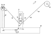
- FIG. 1 is a side elevation view of a printer paper spooler with error condition detector from a first slot structure side;
- FIG. 2 is a side elevation view of a portion the printer paper spooler with error condition detector from a second slot structure side;
- FIG. 3 is an end elevation view of a take-up tower end of the printer paper spooler with error condition detector of FIG. 1 ;
- FIG. 4 is an end elevation view of a slot section end of the printer paper spooler with error condition detector of FIG. 1 without receipt printer paper, including a bobbin disposed in a detecting light beam;
- FIG. 5 is the end elevation view of FIG. 4 , with the bobbin disposed outside of the detecting light beam.
- the printer paper spooler with error condition detector 10 spools printed receipt paper and detects receipt paper printer error conditions, such as paper jams, without the need for continuous monitoring by a printer-testing technician.
- the printer paper spooler with error condition detector 10 includes a first slot structure 12 including a light emitting diode (LED hereinafter) 18 and defining a first slot cavity 13 , and a second slot structure 14 including a phototransistor 20 and defining a second slot cavity 15 .
- LED light emitting diode
- a bobbin 16 including a first extension 16 a and a second extension 16 b , and a take-up tower 22 , including a take-up reel 24 and a take-up motor 26 .
- the first slot structure 12 , the second slot structure 14 , and the take-up tower 22 are disposed on a base structure 27 , which includes a base parallel port 29 and data wiring (illustrated in the figures as data wiring 31 a and 31 b ).
- a spooler control program (not illustrated) that is associable with the phototransistor 20 , take-up motor 26 , and a printer control program via a data exchange connection.
- the spooler control program and printer control program are included in at least one of a server and a personal computer (neither illustrated), which includes a server parallel port (not illustrated) and is associable with the base structure 27 via a cable 25 .
- the first slot structure 12 is associable with the second slot structure 14 via the bobbin 16 and a detecting light beam 28 emitted from the LED 18 and extending to the phototransistor 20 , which is positioned on the second slot structure 14 to selectively detect and receive the detecting light beam 28 .
- the bobbin 16 is disposed between the first slot structure 12 and second slot structure 14 , and held therein via associations between the first extension 16 a and the first slot cavity 13 and the second extension 16 b and the second slot cavity 15 .
- Each extension 16 a–b is configured to be associable with its corresponding slot cavity ( 13 and 15 respectively) via an actuating device (not illustrated), such as a spring, disposed within the bobbin 16 and/or extensions 16 a–b .
- actuating devices allow the extensions 16 a–b to be pushed, against the force of the actuating device/spring, inwardly towards the bobbin 16 , wherein the extensions 16 a–b will re-extend after pushing ceases, and may enter the slot cavities 13 and 15 upon this re-extension.
- the bobbin 16 may traverse a length 30 of the slot cavities 13 and 15 in response to forces that will be discussed in greater detail below.
- the bobbin 16 and thus the first slot structure 12 and second slot structure 14 , are associable with the take-up reel 24 , and thus take-up tower 22 , via printed receipt paper 32 .
- the printed receipt paper 32 is supplied by a receipt paper roll 34 and becomes printed by traveling through a receipt paper printer (printer hereinafter).
- This printer may be any receipt paper printing mechanism suitable to the desired end purpose of printing on receipt paper.
- the printer is represented in FIG. 1 at printer area 36 (not illustrated to actually contain a printer in the illustration), and it should be appreciated that all paper emerging from a side of the printer area 36 closest to the bobbin 16 is the printed receipt paper 32 in FIG. 1 .
- the take-up reel 24 which is powered by the take-up motor 26 , revolves as shown at revolution direction 38 , and pulls/takes-up the printed receipt paper 32 from the printer area 36 , under the bobbin 16 (to which it is contacting), and onto the take-up reel 24 .
- the take-up reel 24 By “taking-up” excess paper onto the take-up reel, printed receipt paper 32 does not does not have to be caught in trash bins from which the paper may overflow and interfere with the printing process.
- the base structure 27 serves as a base for the slot structures 12 and 14 and the take-up tower 22 , and is associable with at least one of the personal computer and the server (for simplicity purposes, “at least one of the personal computer and the server” will be referred to as the server hereinafter), which is also associable with the printer (represented in the illustrations at printer area 36 ).
- the server is associable with the base structure 27 via the cable, which is connectable to the base parallel port 29 and the server parallel port, thus extending from the base structure 27 to the server.
- the data wiring 31 a (briefly introduced above) connects the base parallel port 29 with the phototransistor 20 , and transports phototransistor data (i.e.
- the phototransistor data may then be transported from the base parallel port 29 to the server parallel port via the cable, wherein the server includes the spooler control program (briefly mentioned above) that deciphers the phototransistor data.
- the spooler control program may then create resultant data from the phototransistor data, and transport the resultant data from the server parallel port to the base parallel port 29 via the cable 25 , and/or transport the resultant data to another program within the server such as a WINIOTEST type program or other printer control program that can control printer operation.
- Resultant data transported to the base parallel port 29 is further transported to the take-up motor 26 via the data wiring 31 b (also briefly introduced above), wherein the resultant data will control take-up motor 26 function (which will also be discussed in greater detail below).
- the data wiring 31 a and 31 b may be associated with a circuit board that is also disposed within the base structure 27 , wherein the circuit board aids in producing the phototransistor data and deciphering the resultant data.
- the data wiring 31 a–b , base parallel port 29 , server parallel port, and cable 25 achieve the data exchange connection between the spooler control program and the phototransistor 20 and take-up motor 26 .
- the bobbin 16 will rest in the path of the detecting light beam 28 until the take-up motor 26 activates the rotation of the take-up reel, typically at the start of the printing process. Once this activation takes place, the bobbin 16 will be positioned outside of the detecting light beam 28 during most printing conditions. This is because the take-up reel 24 causes tension within the printed receipt paper 32 , creating a force in the printed receipt paper 32 that holds the bobbin 16 above the detecting light beam 28 .
- the spooler control program will then recognize this data, and take action if the detecting light beam 28 remains interrupted for an amount of time pre-programmed into the spooler control program. Once this time threshold is reached (the time threshold may be varied within the spooler control program), the spooler control program will send resultant data, to the printer control program, wherein the resultant data signals the error condition and instructs the printer control program to stop the printing process. By instructing this printing stoppage upon exhaustion of the receipt paper supply, a truer test of printer life can be achieved, while preventing damage to the printer paten and clutch.
- the spooler control program will also send the resultant data to the take-up motor 26 (via the cable 25 , base parallel port 29 , and data wiring 31 b ), instructing the take-up motor 26 to also cease operation, saving take-up motor 26 life. It should be further appreciated that the bobbin 16 would also fall into the detecting light beam 28 , causing the same spooler control program reaction, if the take-up reel 24 became to full. This is because a full take-up reel 24 would stop revolving, eliminating tension in the printed receipt paper 32 and causing the bobbin 16 to fall.
- Another error condition would occur if there were a paper jam in the printer at the printer area 26 .
- a paper jam could cause one of two bobbin 16 reactions. Referring to a first reaction caused by a paper jam, the revolving of the take-up reel 24 and the resulting tension in the printed receipt paper 32 (which is now jammed and no longer moving toward the take-up reel 24 ) could cause the bobbin 16 to rise to the respective top of the length 30 of the slot cavities 13 and 15 , and produce a force/tension great enough to tear the printed receipt paper 32 .
- the revolving of the take-up reel again causes the bobbin 16 to rise to the respective top of the length 30 of the slot cavities 13 and 15 , but in this second scenario, there is not enough force/tension to cause the printed receipt paper 32 to tear. If the paper does not tear, the bobbin 16 will remain held at the respective top of the length 30 , outside of the detecting light beam 28 . With the detecting light beam 28 thus continuously uninterrupted, the phototransistor 20 would pass this phototransistor data (about a continuous uninteruption) through the data wiring 31 a to the base parallel port 29 , into the cable 25 , and ultimately to the spooler control program in the server.
- the spooler control program will then recognize this data, and take action if the detecting light beam 28 remains uninterrupted for an amount of time pre-programmed into the spooler control program.
- the time threshold may also be varied within the spooler control program, though likely set to correspond with a little more than the amount of time it takes for an entire receipt paper roll 34 to be exhausted
- the spooler control program will send resultant data to the printer control program, wherein the resultant data signals the error condition and instructs the printer control program to stop the printing process.
- the spooler control program will also send the resultant data to the take-up motor 26 (via the cable 25 , base parallel port 29 , and data wiring 31 b ), instructing the take-up motor 26 to also cease operation, saving take-up motor 26 life.
- the spooler control program may be set to increase power to the take-up motor 26 as the bobbin's 16 time outside of the detecting light beam 28 increases. This will allow power to the take-up motor 26 to increase as the roll of printed receipt paper 32 around the take-up reel 24 grows.
- the amount of power required to turn a small roll will correspond with the amount of power supplied to the take-up motor 26 during the initial stages of the process (with power increased only as the roll grow larger at the end of the process), saving take-up motor 26 power.
Landscapes
- Accessory Devices And Overall Control Thereof (AREA)
- Handling Of Sheets (AREA)
Abstract
Description
Claims (7)
Priority Applications (1)
| Application Number | Priority Date | Filing Date | Title |
|---|---|---|---|
| US11/335,124 US7168872B1 (en) | 2006-01-19 | 2006-01-19 | Printer paper spooler with error condition detector |
Applications Claiming Priority (1)
| Application Number | Priority Date | Filing Date | Title |
|---|---|---|---|
| US11/335,124 US7168872B1 (en) | 2006-01-19 | 2006-01-19 | Printer paper spooler with error condition detector |
Publications (1)
| Publication Number | Publication Date |
|---|---|
| US7168872B1 true US7168872B1 (en) | 2007-01-30 |
Family
ID=37681782
Family Applications (1)
| Application Number | Title | Priority Date | Filing Date |
|---|---|---|---|
| US11/335,124 Expired - Fee Related US7168872B1 (en) | 2006-01-19 | 2006-01-19 | Printer paper spooler with error condition detector |
Country Status (1)
| Country | Link |
|---|---|
| US (1) | US7168872B1 (en) |
Cited By (3)
| Publication number | Priority date | Publication date | Assignee | Title |
|---|---|---|---|---|
| US20090117978A1 (en) * | 2007-05-30 | 2009-05-07 | Aristocrat Technologies Australia Pty Limited | Method of gaming, a gaming system and a game controller |
| US20150199119A1 (en) * | 2006-03-31 | 2015-07-16 | Google Inc. | Optimizing web site images using a focal point |
| US10311676B2 (en) | 2010-05-25 | 2019-06-04 | Aristocrat Technologies Australia Pty Limited | Method of gaming, a gaming system and a game controller |
Citations (17)
| Publication number | Priority date | Publication date | Assignee | Title |
|---|---|---|---|---|
| US3917142A (en) | 1974-04-04 | 1975-11-04 | Data Products Corp | Paper motion sensor apparatus |
| US3958735A (en) | 1975-02-18 | 1976-05-25 | Teletype Corporation | Method and apparatus for detecting paper drive malfunctioning in an automatic printer |
| JPH02192971A (en) | 1989-01-20 | 1990-07-30 | Nec Corp | Paper jam detecting mechanism |
| JPH05186094A (en) | 1991-12-28 | 1993-07-27 | Kyocera Corp | Image forming system |
| JPH08169633A (en) | 1994-12-20 | 1996-07-02 | Nec Data Terminal Ltd | Paper jam detecting mechanism |
| US5615876A (en) | 1995-12-08 | 1997-04-01 | Hewlett-Packard Company | Apparatus and method for sensing accordion jams in a laser printer |
| US5685655A (en) | 1995-12-12 | 1997-11-11 | Ncr Corporation | Security system for unattended printing mechanism |
| US5709488A (en) * | 1996-01-18 | 1998-01-20 | Brother Kogyo Kabushiki Kaisha | Printer |
| US5713059A (en) | 1995-03-25 | 1998-01-27 | Asahi Kogaku Kogyo Kabushiki Kaisha | Paper jam detector for electrophotographic printer |
| US5725321A (en) | 1995-12-07 | 1998-03-10 | Interbold | Journal printer paper feed fault detection system for automated teller machine |
| US5788384A (en) * | 1996-05-10 | 1998-08-04 | Monarch Marking Systems, Inc. | Printer with ink ribbon spool electric motors |
| JPH10245140A (en) | 1997-03-05 | 1998-09-14 | Seiko Epson Corp | Printer and recording paper jam processing method thereof |
| JPH10265109A (en) | 1997-03-24 | 1998-10-06 | Kouon:Kk | Lengthy sheet article taking-up device |
| US5938350A (en) * | 1997-06-19 | 1999-08-17 | Datamax Corporation | Thermal ink printer with ink ribbon supply |
| JPH11277819A (en) | 1998-02-02 | 1999-10-12 | Seiko Epson Corp | Printing medium clogging detection device of printing device and printing device |
| JP2000079734A (en) | 1998-09-07 | 2000-03-21 | Nec Kofu Ltd | Paper feed-detecting mechanism for thermal printer |
| US7018119B2 (en) * | 2003-05-21 | 2006-03-28 | Seiko Epson Corporation | Rolled paper holder and image forming apparatus incorporating the same |
-
2006
- 2006-01-19 US US11/335,124 patent/US7168872B1/en not_active Expired - Fee Related
Patent Citations (18)
| Publication number | Priority date | Publication date | Assignee | Title |
|---|---|---|---|---|
| US3917142A (en) | 1974-04-04 | 1975-11-04 | Data Products Corp | Paper motion sensor apparatus |
| US3958735A (en) | 1975-02-18 | 1976-05-25 | Teletype Corporation | Method and apparatus for detecting paper drive malfunctioning in an automatic printer |
| JPH02192971A (en) | 1989-01-20 | 1990-07-30 | Nec Corp | Paper jam detecting mechanism |
| JPH05186094A (en) | 1991-12-28 | 1993-07-27 | Kyocera Corp | Image forming system |
| JPH08169633A (en) | 1994-12-20 | 1996-07-02 | Nec Data Terminal Ltd | Paper jam detecting mechanism |
| US5713059A (en) | 1995-03-25 | 1998-01-27 | Asahi Kogaku Kogyo Kabushiki Kaisha | Paper jam detector for electrophotographic printer |
| US5725321A (en) | 1995-12-07 | 1998-03-10 | Interbold | Journal printer paper feed fault detection system for automated teller machine |
| US5879092A (en) | 1995-12-07 | 1999-03-09 | Interbold | Paper feed fault detection system for automated banking machine |
| US5615876A (en) | 1995-12-08 | 1997-04-01 | Hewlett-Packard Company | Apparatus and method for sensing accordion jams in a laser printer |
| US5685655A (en) | 1995-12-12 | 1997-11-11 | Ncr Corporation | Security system for unattended printing mechanism |
| US5709488A (en) * | 1996-01-18 | 1998-01-20 | Brother Kogyo Kabushiki Kaisha | Printer |
| US5788384A (en) * | 1996-05-10 | 1998-08-04 | Monarch Marking Systems, Inc. | Printer with ink ribbon spool electric motors |
| JPH10245140A (en) | 1997-03-05 | 1998-09-14 | Seiko Epson Corp | Printer and recording paper jam processing method thereof |
| JPH10265109A (en) | 1997-03-24 | 1998-10-06 | Kouon:Kk | Lengthy sheet article taking-up device |
| US5938350A (en) * | 1997-06-19 | 1999-08-17 | Datamax Corporation | Thermal ink printer with ink ribbon supply |
| JPH11277819A (en) | 1998-02-02 | 1999-10-12 | Seiko Epson Corp | Printing medium clogging detection device of printing device and printing device |
| JP2000079734A (en) | 1998-09-07 | 2000-03-21 | Nec Kofu Ltd | Paper feed-detecting mechanism for thermal printer |
| US7018119B2 (en) * | 2003-05-21 | 2006-03-28 | Seiko Epson Corporation | Rolled paper holder and image forming apparatus incorporating the same |
Cited By (4)
| Publication number | Priority date | Publication date | Assignee | Title |
|---|---|---|---|---|
| US20150199119A1 (en) * | 2006-03-31 | 2015-07-16 | Google Inc. | Optimizing web site images using a focal point |
| US20090117978A1 (en) * | 2007-05-30 | 2009-05-07 | Aristocrat Technologies Australia Pty Limited | Method of gaming, a gaming system and a game controller |
| US10311676B2 (en) | 2010-05-25 | 2019-06-04 | Aristocrat Technologies Australia Pty Limited | Method of gaming, a gaming system and a game controller |
| US11043073B2 (en) | 2010-05-25 | 2021-06-22 | Aristocrat Technologies Australia Pty Limited | Symbol interchange method, gaming machine, and computer readable media |
Similar Documents
| Publication | Publication Date | Title |
|---|---|---|
| KR100739736B1 (en) | Image forming apparatus and paper feeding method applied thereto | |
| KR100431005B1 (en) | apparatus for sensing paper for use in an office machine | |
| CN110167760A (en) | Multiple feedings prevent the service condition of roller from determining | |
| US10815089B2 (en) | Medium winding device and printing system | |
| US7168872B1 (en) | Printer paper spooler with error condition detector | |
| CN101389478A (en) | Printing machines and paper discharge devices for printing machines | |
| CN108656764B (en) | Printing device and control method of printing device | |
| US9802429B2 (en) | Media conveyance device, printer, and control method of a media conveyance device | |
| JP6651943B2 (en) | PRINTING APPARATUS AND CONTROL METHOD OF PRINTING APPARATUS | |
| JP5418149B2 (en) | Printing apparatus and printing medium discrimination method | |
| JP2010215375A (en) | Method for adjusting sensor for paper sheet | |
| US8091476B2 (en) | Web conveyance method and apparatus of tandem printing system | |
| KR20030059561A (en) | Image forming device having differentiating varieties of printing medium and driving controlling method of thereof | |
| JPH05155081A (en) | Printer | |
| JP2007069610A (en) | Web rupture monitoring equipment of rotary press | |
| JP2009028959A (en) | Sheet-fed printer | |
| CN114161846B (en) | Printer with a printer body | |
| KR20190014986A (en) | Sheet supplying apparatus and image forming apparatus having the smae | |
| JP2002338113A (en) | Roll sheet supplying device and recording device | |
| WO1991012968A1 (en) | Image forming apparatus | |
| KR100343154B1 (en) | Paper Feeder | |
| EP4067273B1 (en) | Sheet feeding apparatus and image forming apparatus | |
| JP7800252B2 (en) | Printing device and printing device control method | |
| JP4993663B2 (en) | Image forming system | |
| CN110014732B (en) | Paper tape conveying device and printing system |
Legal Events
| Date | Code | Title | Description |
|---|---|---|---|
| AS | Assignment |
Owner name: INTERNATIONAL BUSINESS MACHINES CORPORATION, NEW Y Free format text: ASSIGNMENT OF ASSIGNORS INTEREST;ASSIGNORS:CAPPS, WILLIAM R.;HOWARD, THOMAS J.;VANDERPOOL III, RICHARD W.;REEL/FRAME:017309/0793 Effective date: 20060117 |
|
| FEPP | Fee payment procedure |
Free format text: PAYOR NUMBER ASSIGNED (ORIGINAL EVENT CODE: ASPN); ENTITY STATUS OF PATENT OWNER: LARGE ENTITY |
|
| FPAY | Fee payment |
Year of fee payment: 4 |
|
| AS | Assignment |
Owner name: TOSHIBA GLOBAL COMMERCE SOLUTIONS HOLDINGS CORPORA Free format text: PATENT ASSIGNMENT AND RESERVATION;ASSIGNOR:INTERNATIONAL BUSINESS MACHINES CORPORATION;REEL/FRAME:028895/0935 Effective date: 20120731 |
|
| FPAY | Fee payment |
Year of fee payment: 8 |
|
| FEPP | Fee payment procedure |
Free format text: MAINTENANCE FEE REMINDER MAILED (ORIGINAL EVENT CODE: REM.); ENTITY STATUS OF PATENT OWNER: LARGE ENTITY |
|
| LAPS | Lapse for failure to pay maintenance fees |
Free format text: PATENT EXPIRED FOR FAILURE TO PAY MAINTENANCE FEES (ORIGINAL EVENT CODE: EXP.); ENTITY STATUS OF PATENT OWNER: LARGE ENTITY |
|
| STCH | Information on status: patent discontinuation |
Free format text: PATENT EXPIRED DUE TO NONPAYMENT OF MAINTENANCE FEES UNDER 37 CFR 1.362 |
|
| FP | Lapsed due to failure to pay maintenance fee |
Effective date: 20190130 |