US7167865B1 - Collaborative environment for producing software products - Google Patents
Collaborative environment for producing software products Download PDFInfo
- Publication number
- US7167865B1 US7167865B1 US10/610,424 US61042403A US7167865B1 US 7167865 B1 US7167865 B1 US 7167865B1 US 61042403 A US61042403 A US 61042403A US 7167865 B1 US7167865 B1 US 7167865B1
- Authority
- US
- United States
- Prior art keywords
- stages
- model
- elements
- software product
- resources
- Prior art date
- Legal status (The legal status is an assumption and is not a legal conclusion. Google has not performed a legal analysis and makes no representation as to the accuracy of the status listed.)
- Expired - Lifetime, expires
Links
- 238000000034 method Methods 0.000 claims abstract description 84
- 238000004891 communication Methods 0.000 claims abstract description 61
- 238000004519 manufacturing process Methods 0.000 claims abstract description 25
- 238000011161 development Methods 0.000 claims abstract description 17
- 238000003908 quality control method Methods 0.000 claims abstract description 6
- 230000008859 change Effects 0.000 claims description 6
- 230000000644 propagated effect Effects 0.000 claims 4
- 238000004590 computer program Methods 0.000 claims 1
- 230000008569 process Effects 0.000 description 60
- 238000012800 visualization Methods 0.000 description 28
- 230000007246 mechanism Effects 0.000 description 18
- 230000018109 developmental process Effects 0.000 description 15
- 230000008901 benefit Effects 0.000 description 14
- 230000004044 response Effects 0.000 description 13
- 230000001360 synchronised effect Effects 0.000 description 13
- 230000006870 function Effects 0.000 description 8
- 230000000875 corresponding effect Effects 0.000 description 6
- 238000012360 testing method Methods 0.000 description 6
- 239000002131 composite material Substances 0.000 description 4
- 238000005516 engineering process Methods 0.000 description 4
- 230000014509 gene expression Effects 0.000 description 4
- 230000009471 action Effects 0.000 description 3
- 238000013461 design Methods 0.000 description 3
- 238000010586 diagram Methods 0.000 description 3
- 238000010276 construction Methods 0.000 description 2
- 230000000694 effects Effects 0.000 description 2
- 230000003116 impacting effect Effects 0.000 description 2
- 230000008520 organization Effects 0.000 description 2
- 208000036993 Frustration Diseases 0.000 description 1
- BPQQTUXANYXVAA-UHFFFAOYSA-N Orthosilicate Chemical compound [O-][Si]([O-])([O-])[O-] BPQQTUXANYXVAA-UHFFFAOYSA-N 0.000 description 1
- 230000002776 aggregation Effects 0.000 description 1
- 238000004220 aggregation Methods 0.000 description 1
- 238000013459 approach Methods 0.000 description 1
- 230000003111 delayed effect Effects 0.000 description 1
- 238000001514 detection method Methods 0.000 description 1
- 230000007257 malfunction Effects 0.000 description 1
- 230000005055 memory storage Effects 0.000 description 1
- 238000012986 modification Methods 0.000 description 1
- 230000004048 modification Effects 0.000 description 1
- 238000012544 monitoring process Methods 0.000 description 1
- 230000006855 networking Effects 0.000 description 1
- 238000012545 processing Methods 0.000 description 1
- 230000000750 progressive effect Effects 0.000 description 1
- 230000002035 prolonged effect Effects 0.000 description 1
- 238000011084 recovery Methods 0.000 description 1
- 230000010076 replication Effects 0.000 description 1
- 230000003068 static effect Effects 0.000 description 1
- 238000003860 storage Methods 0.000 description 1
- 239000000126 substance Substances 0.000 description 1
- 230000007704 transition Effects 0.000 description 1
Images


Classifications
-
- G—PHYSICS
- G06—COMPUTING; CALCULATING OR COUNTING
- G06Q—INFORMATION AND COMMUNICATION TECHNOLOGY [ICT] SPECIALLY ADAPTED FOR ADMINISTRATIVE, COMMERCIAL, FINANCIAL, MANAGERIAL OR SUPERVISORY PURPOSES; SYSTEMS OR METHODS SPECIALLY ADAPTED FOR ADMINISTRATIVE, COMMERCIAL, FINANCIAL, MANAGERIAL OR SUPERVISORY PURPOSES, NOT OTHERWISE PROVIDED FOR
- G06Q10/00—Administration; Management
- G06Q10/10—Office automation; Time management
-
- Y—GENERAL TAGGING OF NEW TECHNOLOGICAL DEVELOPMENTS; GENERAL TAGGING OF CROSS-SECTIONAL TECHNOLOGIES SPANNING OVER SEVERAL SECTIONS OF THE IPC; TECHNICAL SUBJECTS COVERED BY FORMER USPC CROSS-REFERENCE ART COLLECTIONS [XRACs] AND DIGESTS
- Y10—TECHNICAL SUBJECTS COVERED BY FORMER USPC
- Y10S—TECHNICAL SUBJECTS COVERED BY FORMER USPC CROSS-REFERENCE ART COLLECTIONS [XRACs] AND DIGESTS
- Y10S707/00—Data processing: database and file management or data structures
- Y10S707/99941—Database schema or data structure
- Y10S707/99942—Manipulating data structure, e.g. compression, compaction, compilation
-
- Y—GENERAL TAGGING OF NEW TECHNOLOGICAL DEVELOPMENTS; GENERAL TAGGING OF CROSS-SECTIONAL TECHNOLOGIES SPANNING OVER SEVERAL SECTIONS OF THE IPC; TECHNICAL SUBJECTS COVERED BY FORMER USPC CROSS-REFERENCE ART COLLECTIONS [XRACs] AND DIGESTS
- Y10—TECHNICAL SUBJECTS COVERED BY FORMER USPC
- Y10S—TECHNICAL SUBJECTS COVERED BY FORMER USPC CROSS-REFERENCE ART COLLECTIONS [XRACs] AND DIGESTS
- Y10S707/00—Data processing: database and file management or data structures
- Y10S707/99941—Database schema or data structure
- Y10S707/99943—Generating database or data structure, e.g. via user interface
-
- Y—GENERAL TAGGING OF NEW TECHNOLOGICAL DEVELOPMENTS; GENERAL TAGGING OF CROSS-SECTIONAL TECHNOLOGIES SPANNING OVER SEVERAL SECTIONS OF THE IPC; TECHNICAL SUBJECTS COVERED BY FORMER USPC CROSS-REFERENCE ART COLLECTIONS [XRACs] AND DIGESTS
- Y10—TECHNICAL SUBJECTS COVERED BY FORMER USPC
- Y10S—TECHNICAL SUBJECTS COVERED BY FORMER USPC CROSS-REFERENCE ART COLLECTIONS [XRACs] AND DIGESTS
- Y10S707/00—Data processing: database and file management or data structures
- Y10S707/99941—Database schema or data structure
- Y10S707/99944—Object-oriented database structure
- Y10S707/99945—Object-oriented database structure processing
Definitions
- the present invention generally relates to the area of distributed systems over data networks.
- the present invention relates to techniques for providing infrastructures to utilize distributed resources over data networks.
- the present invention relates to a method and system for providing a model that centrically models distributed resources across one or more networks in accordance with a desired task, establishing direct communication sessions between two network nodes, managing applications depending on multiple resources, and a method, a process, and a system for providing a synchronized environment for producing software products, wherein the synchronized environment is based upon a logic model of a collection of different stages or phases in deploying the software products.
- IT information technology
- IT is a term that encompasses all forms of technology used to create, store, exchange, and use information in its various forms (e.g., business data, voice conversations, still images, motion pictures, multimedia presentations, and other forms).
- IT is a strategic resource to a company. Dynamic use of IT can dramatically reduce costs and thereby improve a company's operating margin, accelerate the time to market for new products and services a business may offer, increase response times for internal and external customers, improve system reliability, up time, and availability.
- the present invention is related to processes, systems, architectures and software products for modeling resources distributed across a network, communication means to support for modeling resources in a distributed and collaborative manner, managing applications depending on multiple resources, and providing a centric and synchronized environment for setting up and producing software products in different phases or stages.
- a model is initiated as a project model and finished as a logic model at a rendezvous to include spaces or elements, each of the elements corresponding to a node (e.g., an instance of a resource), relationships between or among the elements, or including instructions or data.
- a logic model or simply, a model is a collection of elements and relationships between the elements, and centrally modeling a collection of resources for a given task.
- a model can have a different meaning given a different context.
- a model can be presented in many ways depending on how the model is used.
- a model is provided as an abstraction mechanism for modeling resources that tie to physical entities and/or virtual entities that may or may not have any physical representation.
- a model is essentially a collection of metadata about one or more resources.
- a model can include data objects, processes or instructions as well.
- a model may have a set of constraints which become part of the model's metadata.
- a model can be configured to include rules either pre-defined or added dynamically. Constraints and rules may be extended to give a set of instructions for visualization of the model.
- a model is created or configured to include a collection of metadata to model a dynamic system that utilizes resources in a distributed network.
- the elements in the model are categorized into a number of classes, thus to represent the relationships between the elements in N-dimension, wherein N is the number of classes.
- Mechanisms are provided, based on a query or queries, to extract a visualization out of the N-dimension such that at any time a particular or desired perspective of the relationships of the resources can be provided in accordance with the query or queries.
- direct communications sessions are respectively established among a plurality of nodes. These nodes may join to collaboratively develop, manage and update a model of a collection of resources, provide support and other means to accomplish a model or communicate between each other through a common model. With established direct communication sessions, data or sources in one node can be transported to and synchronized in another node. According to one embodiment, various types of access control can be provided to control the communications with there nodes, for example, to retire a session with a node, limit or control certain types of accesses from a node.
- an established model for setup is applied to applications of producing software products.
- the model provides a centric environment or setup that is applicable to each of the stages, synchronizes changes and facilitates communications among the stages, thus greatly improving collaborations, communications and efficiency among the stages.
- a model is created to model all resources in one or more files supporting an application (e.g. a website) depending on the resources and provide a visualization of relationships among the resources such that a collaborative platform is provided for management of the resources for the application.
- an application e.g. a website
- the present invention may be implemented as a system, an architecture or process, or employed in software, hardware or a combination of software and hardware.
- One of these benefits, features and advantages is the mechanism provided in the present invention to model distributed resources for a given task in a collection of elements referred to as a model.
- the model is generic enough and can be configured to accomplish a task or tasks that are otherwise difficult to be done in a single or isolated computing environment.
- FIG. 1A shows a basic system configuration in which the present invention may be practiced in accordance with one embodiment of the present invention
- FIG. 1B shows internal construction blocks of a system in which the present invention may be implemented and executed to achieve desired results contemplated in the present invention
- FIG. 2A illustrates a collection of nodes in which each node represents a resource or an instance of the resource
- FIG. 2B shows that original unrelated nodes can now communicate each other via a model of a collection of elements, each pertaining to a node;
- FIG. 2C illustrates a communication diagram between two nodes NodeA and NodeB for establish a direct communication session
- FIG. 2D shows an exemplary messaging mechanism that may be used in a direct communication session between the two nodes
- FIG. 2E shows a flowchart or process of establishing a direct communication session between two nodes and may be further understood in conjunction with FIG. 2C ;
- FIG. 3A shows an exemplary model in reference to FIG . 2 A and in accordance with one aspect of the present invention
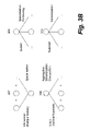
- FIG. 3B shows four exemplary space operations that may be used to establish relationships between elements in a model
- FIG. 3C shows an improved model over that shown in FIG. 3A and includes additional four elements dataA, dataB, phase 1 and phase 2 ;
- FIG. 3D depicts a collection of cubes with each of the cubes representing possible relationships among three elements
- FIG. 3E shows a flowchart or process of generating or establishing a model to model a plurality of distributed resources for a desired task or tasks
- FIG. 3F illustrates a visualization extracted from the model shown in FIG. 3D in accordance with a query or queries
- FIG. 3G shows a flowchart or process of generating a visualization of an N-dimensional model in accordance with a query or queries
- FIG. 4A shows an exemplary graphic environment that may be used to create a logic model of FIG. 3C ;
- FIG. 4B shows that the model is partially expanded and the relationships between some of the elements can be seen in a display of the graphic environment of FIG. 4A ;
- FIG. 4C shows another display in the graphic environment that shows a number of nodes have been invited to participate the development, management or updating of the model
- FIG. 5A shows an exemplary configuration for deploying a software product
- FIG. 5B shows one aspect of the present invention that can be used to solve or minimize many of the problems that may be experienced in FIG. 5A , instead of having a different setup for each of the stages, a centralized setup based on a model modeling the stages is provided;
- FIG. 5C shows a flowchart or process of creating a centralized setup based on a logic model
- FIG. 5D illustrates a collection of two versions of relationships between the stages and two resources.
- FIG. 6 shows a flowchart or process of managing a website using the modeling mechanism described herein.
- the present invention is related to processes, systems, architectures and software products for modeling resources distributed across a network, communication means to support for modeling resources in a distributed and collaborative manner, providing a synchronized environment for producing products, and a collaborative platform for managing multiple resources for an application.
- a model is created as a collection of spaces or elements that at least one of the elements pertains to an instance of a resource or a relationship between or among resources being modeled.
- a graphic environment is provided to facilitate the modeling process and the establishment of the relationships between the elements.
- a command line interface (CLI) is provided to facilitate the modeling process and the establishment of the relationships between the elements.
- the mechanism behind the graphic or CLI environment is respective direct communication sessions established with the resources such that the model is dynamically updated and synchronized.
- a modeling process is extended to establishing a centric environment of producing software products involving a number of progressive or collaborative stages.
- a model is provided as the centric environment (e.g. a setup) to include resource instances of each of the stages thus all stages proceed with respective tasks in accordance with the same model.
- references herein to “one embodiment” or “an embodiment” means that a particular feature, structure, or characteristic described in connection with the embodiment can be included in at least one embodiment of the invention.
- the appearances of the phrase “in one embodiment” in various places in the specification are not necessarily all referring to the same embodiment, nor are separate or alternative embodiments mutually exclusive of other embodiments. Further, the order of blocks in process flowcharts or diagrams representing one or more embodiments of the invention do not inherently indicate any particular order nor imply any limitations in the invention.
- Resource may represent, but not be limited to, a process, an application, a type of source, content, service or machine configured to provide supports to or facilitate a desired task or tasks that can be achieved in a distributed and collaborative manner.
- a database is a resource
- a web service is a resource
- a human via a computer is also a resource.
- Computing device is a physical device.
- a machine can host various resources, as a client, a machine can be used to access various resources over a network, or as one of a group of machines to contribute to a task that can be achieved by the group of machines in a distributed and collaborative manner.
- Host is a machine hosting, executing, providing one or more resources.
- Node is an instance of a resource, and in general, is network addressable.
- a machine may be configured to provide multiple resources, and hence there may be more than one node in a machine.
- there can be multiple users on a node each user defines the boundary of set of elements resident on a node.
- Model is a collection of spaces, metadata, nodes or elements representing one or more resources and relationships thereof, and may be configured to achieve a desired task, execute a project, instruct another machine to perform accordingly or act as a node in another model.
- a model can have a different meaning in a different context.
- FIGS. 1A–6 Embodiments of the present invention are discussed herein with reference to FIGS. 1A–6 . However, those skilled in the art will readily appreciate that the detailed description given herein with respect to these figures is for explanatory purposes as the invention extends beyond these limited embodiments.
- FIG. 1A shows a basic system configuration in which the present invention may be practiced in accordance with one embodiment thereof.
- a network 108 that may be a public or a private network (e.g., the Internet or a local area network).
- Each of the machines 102 – 105 operates independently from others but may provide one or more resources that other machines may need to accomplish a task.
- the machine 102 is configured to execute an application that requires a number of resources to support the execution.
- the machine 102 is not supplied with all of the resources but can be configured to take advantage of the distributed resources in other machines, such as the machines 103 – 105 .
- Each of the machines 103 – 105 may be a server computer, a desktop computer or any other type of computing devices.
- the machine 102 is accessible by other machines (e.g., the machines 111 – 113 ), for example, to execute an application, provide a type of service, data or content.
- the model in the machine 102 is accessed as an instance that in return provides distributed computational capacity.
- the machines 111 – 113 are coupled to a network 110 that may be the same as the network 108 or a different network. In general, the machines 111 – 113 are accessed by human operators to perform certain tasks via the machine 102 .
- each of the machines 102 – 105 and 111 – 113 is loaded with one type of an executable version of one embodiment of the present invention or configured in accordance with the present invention such that a high efficient collaboration computing environment can be achieved.
- FIG. 1B shows exemplary internal construction blocks of a system 118 in which the present invention may be implemented and executed.
- the system 118 may correspond to one of the machines shown in FIG. 1A .
- the system 118 includes a central processing unit (CPU) 122 interfaced to a data bus 120 and a device interface 124 .
- the CPU 122 executes certain instructions to manage all devices and interfaces coupled to data bus 120 for synchronized operations and the device interface 124 may be coupled to an external device such as another computing machine hence one or more resources in the computing machine may be utilized.
- Also interfaced to the data bus 120 is a display interface 126 , a network interface 128 , a printer interface 140 and a disk drive interface 148 .
- a complied and linked version or an executable version of one embodiment of the present invention is loaded into the storage 146 through the disk drive interface 138 , the network interface 128 , the device interface 124 or other interfaces coupled to the data bus 120 .
- the main memory 142 such as random access memory (RAM) is also interfaced to the data bus 120 to provide the CPU 122 with the instructions and access to memory storage 146 for data and other instructions, applications or services.
- RAM random access memory
- the CPU 122 is caused to manipulate the data to achieve results contemplated by the present invention.
- the ROM (read only memory) 144 is provided for storing invariant instruction sequences such as a basic input/output operation system (BIOS) for operation of the keyboard 140 , the display 126 and the pointing device 142 , if there are any.
- BIOS basic input/output operation system
- the system 118 is coupled to a network and configured to provide one or more resources to be shared with or executed by another system on the network or simply as an interface to receive data and instructions from a human being.
- FIG. 2A illustrates a collection of nodes 200 in which each node represents a resource or an instance of the resource.
- Each of the nodes is identified by an identifier and configured to include a mechanism (e.g., a software agent or a pointer) used to address or access the resource or a specific computer that the resource is hosted in.
- the node can be identified by a network address (e.g., a uniform resource identifier or URI) or a direct link.
- the identifier includes an address and a specific name of the resource.
- direct communication between two nodes e.g. between the nodes 202 and 212
- sources in one node can be synchronized with those in another node.
- a machine 202 provides three nodes 204 – 206 while two nodes 208 and 210 are respectively from two separate machines. All of the machines are coupled to a network.
- a rendezvous is created (e.g., at the node 212 as shown in the figure) and is configured to dynamically model each of the nodes 204 , 206 , 208 and 210 such that the rendezvous can be readily utilized to accomplish a task without having to have all resources available at one location.
- the rendezvous virtualizes the resources at one location but is depending on the nodes 204 , 206 , 208 and 210 in a distributed fashion.
- the nodes 204 , 206 , 208 and 210 can readily communicate between or among themselves objectively as shown in FIG. 2B in which the nodes 204 and 208 communicate each other and the nodes 208 and 210 communicate each other, all via the model at the rendezvous, thus indirection communication between nodes via a model is now possible.
- each or some of the nodes 204 , 206 , 208 and 210 represents a model (that may represent a collection of resources), thus a new logical model can be established (e.g., at the rendezvous) to represent these models or resources by certain operations (e.g., aggregation).
- a new logic model can be created and shared on each or all of the nodes 204 , 206 , 208 and 210 , the logic model itself could represent a task or process and provides an abstraction in modeling a task in a distributed network.
- FIG. 2C illustrates a communication diagram 220 between two nodes NodeA and NodeB.
- one of the nodes is configured to initiate a session, for example, by sending an invitation request from NodeA to NodeB.
- the invitation request is initiated in a model to facilitate the direction communication between two nodes.
- the invitation request may include criteria and/or access control information. The criteria pertain to what NodeA desires from NodeB while the access control information pertains to how NodeB can participate. If NodeB accepts the invitation requests, NodeB returns an acceptance response to facilitate the establishment of the session.
- the communication protocol for such session may include, but not be limited to, Groove (see www.groove.net) and JXTA (see www.jxta.org).
- Groove see www.groove.net
- JXTA see www.jxta.org
- NodeA is being accessed by a user to establish a model for a task therein.
- the model itself can be an instance represented by NodeA that can be called upon as a resource to join other models.
- the model is depicted as a space or a data set A in FIG. 2C .
- the model requires a resource provided from NodeB that may be remotely located with respect to NodeA over a network (e.g., the Internet), or NodeB is invited to work together with NodeA on the model.
- NodeA is configured to send an invitation request (e.g., by a user or a software agent) to NodeB.
- NodeB Upon receiving the invitation request, NodeB determines whether to join NodeA to participate the task in a collaborative manner. It is now assumed that NodeB is present online and accepts the invitation request and responds to the invitation request with an acknowledgement to thus establish a direct communication session with NodeA. With the established session, the data set A is pushed or transported to NodeB over the network. Although there appear two copies of the data set A on either one of the nodes, they are synchronized, an action to the data set on one end is synchronously or asynchronously reflected on the other end.
- the communication session can be made to be subject conditions that may be imposed by NodeA and/or NodeB.
- the session is expired at a specific time, NodeB is no longer part of the model after a certain time, NodeA or NodeB may receive, transmit or communicated a certain type of data.
- security clearance may be employed in the communication session to ensure that only an authenticated or recognized source may be shared in the model.
- FIG. 2D shows a messaging mechanism 230 , according to one embodiment, to facilitate the establishment of the communication session and direct communication between NodeA and NodeB.
- Blocks 232 – 235 represent respective stacks for a message to get sent. In other words, every message goes through the network layer 235 , the basic point-to-point messaging layer 234 , the retry layer 233 and the queuing layer 232 if applicable.
- the detection of node presence and discovery of nodes 236 and 237 is required and affects the operations of these stacks.
- the network layer 235 covers the network aspect of sending a message.
- the underling protocol could be TCP/IP, HTTP or some other protocol, which is known to those skilled in the art.
- the network layer 235 includes the set of JXTA Functions that provides basic capabilities to establish a communication session (e.g., a JXTA pipe), and endpoint node address for sending a message, and basic send/receive packets over the established session.
- Each node has a name and is uniquely identified by an identifier across a network.
- a node is bound to a network endpoint to make it addressable for messaging purpose, detectable for presence, and discoverable across the network.
- Point-to-point (1:1) messaging through the basic point-to-point messaging layer 234 can be used to handle broadcasting or multicasting messages to multiple nodes (1:N).
- the retry layer 233 provides capabilities of ensuring that a message (e.g., data) is guaranteed to arrive at an intended destination. There are at least two possible causes that a message is not delivered. First, the message never arrives at an intended destination (e.g., NodeB), due to a network problem or problems at a sending node. The second case may be that the receiving node is having problems sending an acknowledgement response or there are network problems preventing it from sending the message. In any case, the retry layer 233 ensures that a message is delivered to a node while a receiving node is configured to recognize and ignore duplicated messages (same message sent multiple times).
- an intended destination e.g., NodeB
- the retry layer 233 ensures that a message is delivered to a node while a receiving node is configured to recognize and ignore duplicated messages (same message sent multiple times).
- the nodes are distributed across a network and can be located remotely with respect to each other. There may not be any control over the operation of these nodes. Therefore, nodes can be online and offline in a very unpredictable manner in addition to other scenarios in which nodes are not responsive.
- the queuing layer 232 provides a mechanism to queue messages if the message could not be delivered.
- FIG. 2E shows a flowchart or process 240 of establishing a direct communication session between two nodes and may be further understood in conjunction with FIG. 4C .
- process 240 can be implemented in software, hardware, or a combination of software and hardware.
- a model is being collaboratively developed, managed, shared or updated by more than one node, in which case, a respective direct communication session will be needed between a hosting node and each of the participating nodes.
- a respective direct communication session will be needed between the model (i.e., a node thereof) and each of the multiple nodes.
- a direct communication session becomes possible between two nodes via the model by establishing multiple direct communication sessions with the model, wherein the two nodes would not otherwise communicate or know each other.
- the node requirements are determined. As described above, the node requirements may be pertaining to distributed resources needed to accomplish a task or those invited to collaboratively accomplish the task, manage, share or update a model related to the task. Regardless of the purposes of these nodes, at 244 , it is determined whether these nodes are known in advance, or in other words, whether the respective address identifiers of these nodes are known. In the case that these nodes are not known, at 246 , one or more criteria queries are configured and sent to all or defined nodes. A query may contain one or more keywords, metadata or desired features or nature of a resource. In one embodiment, such query is broadcast to all nodes that are live at the time of the broadcasting.
- such query is multicast to a set of defined nodes, for example, in a region, a community or an organization. Understandably, only those nodes that are online or live receive the query or queries. In a case in which one or more nodes that are demanded or desired are offline, queries for the offline nodes are queued and delivered when those nodes come back online unless alternative nodes are located or a particular term is expired. At 248 , those nodes that receive the query determine whether the resources pertaining thereto satisfy the query or they are permitted to provide the resources or in what conditions. If no responses are received, the process may go from 248 to 246 to send another query, which may subsequently receive responses as some nodes are turned back online in some other times.
- the process now goes to 254 in which those nodes that are determined to accept the invitation requests respond with an acceptance response.
- the response includes an address identifier of the node or an address identifier of another node that is designated by the node.
- the model 300 can be created at a rendezvous (e.g., in node 212 ).
- the model 300 extends from a root 302 to include layers of elements, each layer including a number of elements.
- the model 300 may be viewed as a graph or tree structure providing a mechanism to group the elements hierarchically.
- Each of the elements may include a number of sub-elements and each of sub-elements may further include a number of elements and so on.
- each of the elements 304 under the root 302 is named after the participating nodes 204 , 206 , 208 and 210 of FIG. 2A , or NodeA, NodeB, NodeC and NodeD, and hence referred to as primary elements.
- primary elements NodeA, NodeB, NodeC and NodeD there are sub-elements describing relationships 304 between the primary elements.
- an element NodeA-NodeB shows that it is an element of a relationship between two elements NodeA and NodeB while the element NodeC-NodeA shows that it is an element of a relationship between two elements NodeC and NodeA.
- relationship elements are inherently one identical element but presented differently for easy visualization.
- relationship elements e.g., the elements NodeA-NodeB and NodeC-NodeA
- relationship elements may represent relationships among several elements or a relationship of the relationships.
- relationship elements may be expressed as a result of certain types of operations.
- Examples of the commonly used operations may be space operations that include intersection, union, subset and superset.
- FIG. 3B shows these four space operations 307 , 308 , 309 , and 310 .
- a relationship element can be created to demonstrate an intersection operation 307 among a number of other elements.
- a relationship element can be created to demonstrate a union operation 308 among a number of other elements.
- the subset operation and superset operations 309 and 310 can be used to move an element down or up one level with respect to its original placement in the mode such that a sub-element or a super-element may be created.
- the model 302 is a collection of elements or relationships among the elements. It should be noted that some of the elements may not pertain to any resources but carry instructions, data, or other information to support the model.
- FIG. 3C shows an improved model 310 over that shown in FIG. 3A by including four elements dataA, dataB, phase 1 and phase 2 .
- the elements dataA and dataB are provided to facilitate the operations of the elements NodeA, NodeB, NodeC and NodeD in two different phases; phase 1 and phase 2 (the relationships between these four elements with other elements are ignored in the figure).
- the improved model 310 can be represented in a 3 dimensional space as a collection of cubes 312 shown in FIG. 3D with each of the cubes representing possible relationships among three elements (e.g., the cubes 314 pertaining to relationships among NodeA, dataB and phase 1 ).
- the 12 elements at the layer 305 in the improved model 310 are categorized into three types of elements in reference to their respective natures, resulting in a 3-dimensional model shown in FIG. 3D .
- a model can be expanded into N dimensions, where N is a number of types of elements or categories the elements may be classified to.
- an N-dimension model is thus provided to interconnect all elements.
- the N-dimension model can be further used as a powerful tool to visualize relationships among all elements.
- a model being a collection of all computing resources in the enterprise can be used to show all relationships between the computing resources and the status thereof.
- the model provides a specific visualization of all resources in the IT infrastructure at any time or a specific time and for any specific criteria.
- FIG. 3E there shows a flowchart or process 330 of generating or establishing a model of modeling a plurality of resources.
- the process 300 can be implemented in software, hardware or a combination of software and hardware.
- the process 330 is implemented in what is commonly called the Eclipse Project (www.eclipse.org) provided by IBM Corporation.
- an initial model for an objective or task is defined, for example, by establishing an initial model that may contain no elements but provides a starting point.
- the initial model which is also referred to as a project model, may be named after the task. Instead of “task” 302 in FIG. 3A , it can be named as “Setup”, etc.
- the available resources to support the task are determined. In general, it needs to determine what a node (or a resource) can contribute to the task. For example, the task is to provide a web service that involves a database and a web application, then at least one of the nodes is an instance of the database and another one is an instance of the web application.
- nodes that may be also included is a node pertaining to instant messaging that provides an interface to receive instructions, data, or commands from a human being.
- an invitation with requirements is broadcasted to silicate participating nodes.
- an invitation may be initiated to be multicasted to known nodes.
- each resource is addressable by an identifier (e.g., a URI) such that a direct communication session between the model (a node itself) and the node is established using a predetermined communication protocol (e.g., JXTA/TCP/IP).
- a predetermined communication protocol e.g., JXTA/TCP/IP.
- an element is chosen to establish necessary relationships with other elements. Depending on the relationships and/or application of the model, super-elements or sub-elements may be created as a result of the relationships of the chosen element with other elements.
- a complete model with N dimensions is generated at 344 . Accordingly, the model generated at 344 is also referred to as a logic model.
- an element in a model shown in FIG. 3A or 3 C are for illustration purpose. There is no requirement that each of the elements must be named after a corresponding node and each of the elements must pertain to a node and a relationship.
- an element is used as an instruction, an operation or a piece of data or the relationship carried in the element is a null relationship with other elements.
- one or more elements in a model can be named after an instruction or a set of data. For example, an element is named as “retrieving a list of test results since last Friday”. When such model is access by a human operator from another node, the naming of the element or the instruction is understandable to the human operator.
- an element in a model can also be named as “hello.exe”, when the model is accessed from a node, a program called “Hello” will be executed.
- model is a collection of elements and relationships among the elements, it is not necessary for each of the elements to pertain to a node or a meaningful relationship between two or more elements.
- One of the key features in the present invention about the model is that the model can be essentially used to model all types of resources, carry instructions or data or other type of sources to achieve a desired task or for a user or an application to achieve a desired task.
- a resource can be a network, an operating system, a communication layer, an application, a database or a service or content provided from a machine.
- a resource can also be a phase, a stage, an instruction (human or machine readable) or a human being that interacts with a machine.
- each of the elements in a model can be expressed in what is called herein metadata.
- the metadata is expressions or assertions about the properties of and relationships between entities that may physical/concrete and logical/abstract.
- physical/concrete entities described by such metadata include machines, people, etc.
- Logical/abstract entities described by such metadata include applications, environment, etc.
- a piece of metadata may include one or more assertions that a particular instance (e.g. a server software) is running on a particular port number, a particular person has a particular email address or is responsible for security in a particular environment, a particular set of configuration parameters in an environment relate to security, or a particular application requires an environment with particular characteristics in order to proceed.
- a particular instance e.g. a server software
- a particular person has a particular email address or is responsible for security in a particular environment
- a particular set of configuration parameters in an environment relate to security
- a particular application requires an environment with particular characteristics in order to proceed.
- the metadata for an element includes one or more statements. At least one of the statements includes a subject, a predicate and an object, each including a URI. In addition, a timestamp may be included in the statement to validate the statement for a predetermined time period.
- the metadata makes it possible to identify, describe, and classify a resource through its ability to construct a statement that links the resource to a specific instance. Given the metadata for each of the elements, it is now possible to represent a model in a graph structure to illustrate the relationships among the elements. With proper interfaces in the metadata, the elements can be rearranged as desired. In operation, an element can be added or deleted without recreating a new model.
- the metadata can be translated in a markup language (e.g., XML or HTML) thus to enable easy data access and exchange.
- An N-dimensional representation of a model is a very powerful tool that can capture information among all the elements in the model.
- a mechanism is designed to query the model so that a specific visualization of the relationship among the elements can be extracted.
- each node can be also expressed in metadata that include a collection of statements, each of the statements including one or more keywords or a subject, a predicate, and an object, and possibly a time stamp and other expression items.
- a query is designed to include criteria for matching some of the metadata. The criteria allow inputs designed to match one or more of the subject, the predicate, the object, the time stamp and other items in a statement so as to extract elements or relationships between the elements in accordance with the criteria.
- One possible matching process is referred to as a straight match, simply to match none, one, two or all of the items in a statement such that one or more elements are thus selected when the corresponding metadata is matched by a query or a chain of queries.
- the matching process is configured to match on multiple (enumerated) values or ranges or even arbitrary boolean-value functions.
- Each element may, in fact, be generalized as a boolean-value function of statement items (e.g., a three boolean-valued function of subject, predicate, and object).
- API application programming interface
- an example is provided herein. It is assumed that a model is constructed to model a directory of a large number of organizations and includes nodes pertaining to resources scattering over a data network (e.g., the Internet or the extranet). To find email addresses of all employees in one organization “mValent”, one may first match triples of the form (X, employer, mValent) and then use the resultant values of X to perform the queries (X, email, Y) to get the desired list as values of Y.
- a data network e.g., the Internet or the extranet
- FIG. 3F illustrates a visualization 348 extracted from the model shown in FIG. 3D .
- the each of the four cubes in the visualization 348 shows the relationships among three elements per the queries, wherein each of the three elements is from a class.
- FIG. 3G shows a flowchart or process 350 of generating a visualization of an N-dimensional model, such as the one generated from the process 330 of FIG. 3E .
- the process 350 can be implemented in software, hardware or a combination of software and hardware.
- the process 350 determines if a model is available.
- the process 350 can be configured to determine if a model created or received is valid in the context of generating a visualization of the model in accordance with a request. It is assumed that the model herein is received or provided and valid.
- the process awaits a request for generating a visualization of the model.
- the request may be provided by or received from a user.
- the user may mean a human user, a software agent, a group of users or a member thereof, a device and/or application(s).
- a software application or agent sometimes needs to generate a visualization as well in order to proceed with a predetermined task. Accordingly, unless specifically stated, the “user” as used herein does not necessarily pertain to a human being.
- the process 350 moves to 356 in which queries are constructed. Depending on implementation, the queries may be provided interactively till a desired visualization is produced, inputted from one or more files or human users.
- the queries are provided to the model (e.g., the metadata of the elements therein).
- a matching process is executed in the model in accordance with a predetermined matching scheme (e.g., straight matching or approximate matching).
- a visualization of the model is generated at 362 in accordance with the queries. In general, if the queries are not constructed properly, the visualization may not be so desired.
- the visualization is checked, for example, any desired relationships are presented or missing. If it is not what is desired, the process 350 goes back to 356 to revise the queries, thus the revised queries are provided to the model. As a result, a revised visualization is generated at 362 and qualified again at 364 . Until qualified or satisfied, the visualization may be regenerated with additional or revised queries.
- a satisfied visualization of the model is produced in accordance with the request.
- FIG. 4A shows an exemplary graphic environment or platform 400 , referred to as mValent Modeling Platform, that may be used to create the logic model 310 of FIG. 3C .
- platform 400 is used to facilitate the understanding of the present invention. Alternations to the platform 400 are possible given the detailed description herein.
- views and displays e.g., command line interface
- the platform 400 shows a display 402 that is provided to allow a user to create a model (e.g., named as a root) for a desired task.
- the display 402 shows a graphic representation of a project model.
- the model can be created by introducing a plurality of elements, each pertains to one or more nodes that are distributed and can be configured collectively to support a task.
- the model can also be created by importing one or more files (e.g., XML or https.conf).
- there is a type display 404 allowing the determination of the type of each of the elements and there is an index display 406 allowing the user to see related information about the elements.
- the display 402 is configured to facilitate the establishment of relationships between the elements or creations of sub-elements or super-elements.
- the display 412 in FIG. 4B shows that the model is partially expanded and the relationships between some of the elements can be seen.
- the individual elements being dataA and dataB
- the group elements being (NodeB, NodeC, NodeD, phase 1 ) and (NodeB, NodeC, NodeD, phase 2 ).
- each of the elements is expressed by metadata.
- the characteristics of an element are described in the corresponding metadata.
- a properties display 412 is used to show the corresponding properties and value of a selected element.
- the display 412 when the element dataA 411 is selected, its property and associated values are revealed (e.g. from the metadata).
- each of the elements in the display 410 has its own properties and associated values and can be shown in the properties display 406 . Further, those elements representing the relationships of others have their composite properties and values and can be displayed as well.
- the group element NodaA-NodeB_NodeC_Node_D_phase 1 413 has composite properties (not shown in figure) respectively from the elements NodeA, NodeB, NodeC, NodeD, and phase 1 .
- a display can be configured to display a visualization of the model according to a set of queries.
- one or more other nodes can be invited to work on a model.
- FIG. 4C shows another display 420 in the platform 400 that shows status of a number of nodes that have been invited to develop, manage or update the model in the display 402 .
- the hosting node is configured to send an invitation request to a node to invite the node to develop, manage or update the model in a collaborative manner.
- the invitation includes access control information or a timer.
- the access control is provided to control the access from the invited node so that only permitted actions may be performed to the model.
- the timer allows the abandonment of the communication between the hosting node and the invited node.
- the node being invited Upon receiving the invitation request, the node being invited is determined whether to access the request or not. In the case in which the node is determined to access the invitation request, the node responds with an acceptance response that facilitates to establish a communication session with the hosting node.
- the mutually agreed communication protocol between the nodes is JXTA.
- a user on the invited node may access the model depending on an access control placed thereupon. If the access control permits, the user can develop the model by introducing additional nodes or models, update the model by deleting or adding one or more elements, reestablishing relationships among the elements and etc. Alternatively, such access may be revoked subject to a term.
- an invitation request has been sent to “john” (a user or node name) and is pending to the acceptance by “john”.
- a user or node named “mary” has accepted an invitation and joined in as a collaborative node to work on the model in the display 402 .
- a node referred to as “data source” was invited but the communication thereto has expired, perhaps, due to a timer, “data source” is no longer accessible but can certainly be re-invited if needed.
- 4C shows exemplary statuses of collaborative nodes. Given the description herein, those skilled in the art can appreciate that there are other possible expressions or implementation to show or control the status of the invited nodes. In addition, it is also possible for the model to be invited as an instance of resource to another model.
- the configuration 500 includes three collective stages, a development stage 502 , a pre-production (QA) stage 504 and a production stage 506 , although other divisions of a process of producing a software product is possible, such as design, build, test and deploy.
- Each of the stages represents a collective effort to achieve a certain status of the product or a desired task.
- the development stage 502 represents that the product is designed and developed by developers (e.g., software engineers)
- the pre-production stage 504 represents that necessary testing or quality control are applied to the product developed in the development stage 502
- the production stage 506 represents a production cycle in which the product is configured in stable conditions and ready for massive productions.
- the environment or setup requirement for each of the three stages is different as required by respective efforts towards the goal of deploying the software product.
- the developers in the development stage 502 create a setup 508 only to facilitate their development needs while testing engineers in the pre-production stage 504 may create a setup 510 only to facilitate their testing needs and the same to the production stage 506 .
- a parameter in the product is adjusted in the pre-production stage 504 , it is difficult to transmit the adjustment to the development stage 502 or the production stage 506 .
- a next version of the product from the development stage 502 may overlook the parameter and the pre-production stage 504 has to again enter the adjusted parameter.
- the developers may not find a need for the parameter to be adjusted.
- many adjustments in the development stage 502 may not demonstrate their significance in other stages since the setup for the development stage 502 is different from the pre-production stage 504 and the production stage 506 .
- various problems, difficulties, incompatibilities or issues can be experienced in the three stages that, nevertheless, work on the same product, resulting in high overhead, inefficiency and delayed time to production.
- FIG. 5B shows one aspect of the present invention that can be used to solve or minimize many of the problems that may be experienced in FIG. 5A .
- the development stage 522 , the pre-production stage 524 , and production stage 526 share a centric setup 528 such that communications among the stages can be made seamlessly.
- anything that have adjusted, changed or updated in one stage can be effectively reflected in the setup which is depended upon by other stages.
- the other stages may act on the changes transparently or non-transparently.
- the centric setup or environment is based on a model including a plurality of elements that may be viewed as at least three groups.
- Each of a first group of elements pertains to an instance of the stage or a local setup of the stage.
- Each of a second group of elements represents a relationship of one element with others elements in the first group.
- Each of a third group of elements carries instructions, data, necessary operations or expressions for.
- FIG. 5C shows a flowchart or process 540 in accordance with FIG. 5B .
- the process 540 can be implemented as a system, a process, a software product, architecture or a combination of any of these and executed in a single machine or in a distributed manner.
- a general setup is created or designated at 542 in accordance with one aspect of the present invention pertaining to creating a logic model as described above.
- the general setup is located on a rendezvous from which all participating stages can access.
- a communication link is preferably established between each of the stages and the general setup at 544 .
- the general setup also referred to as a logic setup, is based upon an initial setup or a project setup at 546 , wherein the initial setup can be newly created or based upon one or more of the setups for the stages.
- the general setup is a logic model to model the stages and the relationships between and among the stages. Instead of executing in a respective setup for a stage, each of the participating stages can now be configured to execute at 548 in the context of the general setup and is subject to changes progressively over time.
- the general setup awaits any updates from any of the participating stages. If an adjustment has to be made in one of the stages, the adjustment will be reflected in the general setup at 552 .
- a version of the general setup that is replaced by a new version can be archived as such a recovery thereof is always possible in the case that the new version is not desirable.
- FIG. 5D illustrates a collection 560 of two versions of relationships between the stages and two resources. It is assumed that there are two resources Resource 1 and Resource 2 (e.g., a database and a set of data) that are needed for each of the stages to perform its own part in the project of deploying the software product. It is further assumed that, over the course of the project, there are two versions 564 and 565 of the resources.
- the general setup can be graphically represented by 12 cubes, each being a relationship among three elements.
- the 12 cubes 560 is a collection of instances of the stages, the resources and the versions and their respective inter-relationships.
- a visualization or composite version 566 of the 12 cubes 560 may be generated in accordance with a query or queries.
- the composite version 566 comprises a cube 567 from Version I of Resource 1 for the development stage, a cube 568 from Version II of Resource 2 for the pre-production stage, and a cube 569 from Version II of Resource 2 for the production stage.
- FIG. 5C can be applied to other infrastructures other than the software product deployment illustrated in FIG. 5B .
- One of the advantages, benefits and features of the present invention is the mechanism provided to support a collaborative environment that utilizes available resources.
- the resources may be located across a network or unknown prior to being called upon into a model for a desired task.
- criteria with conditions may be distributed to a network or a community, those resources willing or configured to support the task may response to the criteria and thus their address identifiers are provided to join in the model.
- FIG. 6 shows a flowchart or process 600 of managing a website using the modeling mechanism described herein.
- the process 600 can be implemented as a system, a process, a software product, architecture or a combination of any of these and executed in a single machine or in a distributed manner.
- a website is controlled by at least one configuration file in a root directory (e.g., wwwroot).
- the configuration file e.g., web.config
- the configuration file is typically written in descriptive language, such as XML, HTML or simply in a text file and comprise statements, each can be comments, declarations, assignments, instructions, data, computations, in accordance with a predetermined set of grammars and syntax.
- At least, there is one resource is referred to in a configuration file for a fairly sophisticated website. For example, after a certain condition is met, a process is let to:
- the process 600 determines if such file is presented or valid.
- One of the purposes here is to produce a logic model out of the configuration file.
- the file is checked with its name extension and/or syntax to ensure that the received file is valid. If the file is not constructed according to a predetermined set of grammars and syntax, the process 600 returns, perhaps with an error message, awaits a next valid file. It is assumed that the file or files for modeling are valid hereinafter.
- the process 600 goes to 604 wherein a project to be associated with the file or files is created.
- the statements in a file are respectively parsed, in accordance with the predetermined set of grammars and syntax, to identify resources being referred to and any relationships between the resources in the file. It is understood to those skilled in the art that a parsing process can be configured to ignore unrelated statements (e.g., comments and declarations) given the known set of grammars and syntax.
- the resource named as 7 and the resource located at 0999 are of interest and thus identified.
- each of the identified resources is assigned as an element (primary) and each of the relationships, if there are any, among the resources is assigned as an element (relationship) as well.
- the file is continued till a last statement is reached. If there are more files, the process 600 may be repeated from 602 to 610 to identify all resources and their relationships with each other presented in the files.
- a logical model utilizing all the resources identified is created. If the platform 400 of FIG. 4A is utilized, the logical model can be displayed in the window 402 of FIG. 4A . With the logical model displayed, the management of the website becomes a lot controllable. There are many operations that may be carried out and verified visually at 614 . For example, elements in the model can be deleted, added or revised to create a revised logical model, another configuration or model may be added as well to be combined with the current model. At 616 , the revised model can be exported, in the same grammars or syntax, to files corresponding to the original files.
- the process 600 allows changes to be visualized and instantly verified. For example, when a change is made, resulting in one element in the model isolated (lost relationships to others), which means, unless for the purpose, that the change will ultimately affect the function of the website because the source is no longer depended upon.
- Those skilled in the art can appreciate that there are numerous advantages, benefits and features that can be enjoyed from the modeling mechanism in managing an enterprise website.
Landscapes
- Engineering & Computer Science (AREA)
- Business, Economics & Management (AREA)
- Strategic Management (AREA)
- Entrepreneurship & Innovation (AREA)
- Human Resources & Organizations (AREA)
- Operations Research (AREA)
- Economics (AREA)
- Marketing (AREA)
- Data Mining & Analysis (AREA)
- Quality & Reliability (AREA)
- Tourism & Hospitality (AREA)
- Physics & Mathematics (AREA)
- General Business, Economics & Management (AREA)
- General Physics & Mathematics (AREA)
- Theoretical Computer Science (AREA)
- Stored Programmes (AREA)
Abstract
Description
-
- getExactSubject( );
- getExactPredicate( );
- getExactObject( );
which each return an array (or null). More advanced queries may be designed as well, the details of which are known to those skilled in the art and are thus omitted to avoid obscuring aspects of the present invention.
| {. . . | |||
| instance | 7 | ||
| port: | 3000 | ||
| . . .} | |||
which means a resource named as 7 and another one located at 0999 are called upon or activated.
Claims (22)
Priority Applications (1)
| Application Number | Priority Date | Filing Date | Title |
|---|---|---|---|
| US10/610,424 US7167865B1 (en) | 2003-06-30 | 2003-06-30 | Collaborative environment for producing software products |
Applications Claiming Priority (1)
| Application Number | Priority Date | Filing Date | Title |
|---|---|---|---|
| US10/610,424 US7167865B1 (en) | 2003-06-30 | 2003-06-30 | Collaborative environment for producing software products |
Publications (1)
| Publication Number | Publication Date |
|---|---|
| US7167865B1 true US7167865B1 (en) | 2007-01-23 |
Family
ID=37663712
Family Applications (1)
| Application Number | Title | Priority Date | Filing Date |
|---|---|---|---|
| US10/610,424 Expired - Lifetime US7167865B1 (en) | 2003-06-30 | 2003-06-30 | Collaborative environment for producing software products |
Country Status (1)
| Country | Link |
|---|---|
| US (1) | US7167865B1 (en) |
Cited By (23)
| Publication number | Priority date | Publication date | Assignee | Title |
|---|---|---|---|---|
| US20050044268A1 (en) * | 2003-07-31 | 2005-02-24 | Enigmatec Corporation | Self-managed mediated information flow |
| US20050060380A1 (en) * | 2003-07-31 | 2005-03-17 | Enigmatec Corporation | Mediated information flow |
| US20050108217A1 (en) * | 2003-08-29 | 2005-05-19 | Horst Werner | Methods and systems for providing a visualization graph |
| US20050114384A1 (en) * | 2003-08-29 | 2005-05-26 | Joerg Beringer | Methods and systems for providing a visualization graph |
| US20050114802A1 (en) * | 2003-08-29 | 2005-05-26 | Joerg Beringer | Methods and systems for providing a visualization graph |
| US20050114383A1 (en) * | 2003-08-29 | 2005-05-26 | Joerg Beringer | Methods and systems for providing a visualization graph |
| US20050229136A1 (en) * | 2004-04-08 | 2005-10-13 | Hitachi, Ltd. | Design support system |
| US20050268284A1 (en) * | 2004-05-27 | 2005-12-01 | International Business Machines Corporation | Uniform references |
| US20060136485A1 (en) * | 2004-11-16 | 2006-06-22 | Peter Yared | Dynamic selection or modification of data management patterns |
| US20070094641A1 (en) * | 2001-12-28 | 2007-04-26 | Darr Timothy P | Product configuration using configuration patterns |
| US20070185893A1 (en) * | 2005-11-25 | 2007-08-09 | Steven Rosenbaum | Method of and a system for logging on a project which contains a footage |
| US20080189678A1 (en) * | 2007-02-02 | 2008-08-07 | Microsoft Corporation | N-tiered applications support via common interface |
| US20090271764A1 (en) * | 2008-04-24 | 2009-10-29 | Gonzales Jesus Orlando Ii | System and method for managing computer environment setup requests |
| DE102008047578A1 (en) * | 2008-09-17 | 2010-04-15 | Siemens Aktiengesellschaft | Method and apparatus for tracking requests in a number of models of a system |
| US20100269087A1 (en) * | 2009-04-20 | 2010-10-21 | Vidya Abhijit Kabra | Software tools usage framework based on tools effective usage index |
| US20110276914A1 (en) * | 2006-11-10 | 2011-11-10 | VirtualAgility, Inc. | System for supporting collaborative activity |
| US20120011097A1 (en) * | 2008-12-11 | 2012-01-12 | International Business Machines Corporation | Method, computer program, and system-model converter for converting system model |
| US20120167048A1 (en) * | 2010-12-23 | 2012-06-28 | Walsh Daniel J | Systems and methods for building software packages in secure development environments |
| US20140157224A1 (en) * | 2012-11-30 | 2014-06-05 | Accenture Global Services Limited | Communications network, computer architecture, computer-implemented method and computer program product for development and management of femtocell-based applications |
| US8812729B2 (en) | 2006-06-12 | 2014-08-19 | Cloudsoft Corporation Limited | Self-managed distributed mediation networks |
| US8977689B2 (en) | 1999-05-07 | 2015-03-10 | Virtualagility Inc. | Managing collaborative activity |
| US9280407B2 (en) | 2014-04-16 | 2016-03-08 | International Business Machines Corporation | Program development in a distributed server environment |
| US10296439B1 (en) * | 2017-11-17 | 2019-05-21 | Amdocs Development Limited | System, method, and computer program for documentation, communication, planning and control of software applications that support business needs |
Citations (9)
| Publication number | Priority date | Publication date | Assignee | Title |
|---|---|---|---|---|
| GB2217070A (en) * | 1988-03-30 | 1989-10-18 | Elverex Ltd | Software testing apparatus |
| US5706405A (en) * | 1992-12-08 | 1998-01-06 | Sterling Software, Inc. | System and method for the design of software systems using a knowledge base |
| US5949999A (en) * | 1996-11-25 | 1999-09-07 | Siemens Corporate Research, Inc. | Software testing and requirements tracking |
| US6138104A (en) * | 1996-04-26 | 2000-10-24 | Workgroup Technology Corporation | Product development system and method using integrated process and data management |
| US6477471B1 (en) * | 1995-10-30 | 2002-11-05 | Texas Instruments Incorporated | Product defect predictive engine |
| US20040073889A1 (en) * | 2002-10-15 | 2004-04-15 | Baecker Thomas Peter | Method of producing a software product |
| US20040268293A1 (en) * | 2003-06-27 | 2004-12-30 | Woodgeard Larry A. | Automating the life cycle of a distributed Computing application |
| US20050010386A1 (en) * | 2003-06-30 | 2005-01-13 | Mvalent, Inc. | Method and system for dynamically modeling resources |
| US20050125772A1 (en) * | 2003-12-09 | 2005-06-09 | Noriaki Kohno | Autonomic computing system, execution environment control method and program |
-
2003
- 2003-06-30 US US10/610,424 patent/US7167865B1/en not_active Expired - Lifetime
Patent Citations (10)
| Publication number | Priority date | Publication date | Assignee | Title |
|---|---|---|---|---|
| GB2217070A (en) * | 1988-03-30 | 1989-10-18 | Elverex Ltd | Software testing apparatus |
| US5022028A (en) * | 1988-03-30 | 1991-06-04 | Elverex Limited | Software verification apparatus |
| US5706405A (en) * | 1992-12-08 | 1998-01-06 | Sterling Software, Inc. | System and method for the design of software systems using a knowledge base |
| US6477471B1 (en) * | 1995-10-30 | 2002-11-05 | Texas Instruments Incorporated | Product defect predictive engine |
| US6138104A (en) * | 1996-04-26 | 2000-10-24 | Workgroup Technology Corporation | Product development system and method using integrated process and data management |
| US5949999A (en) * | 1996-11-25 | 1999-09-07 | Siemens Corporate Research, Inc. | Software testing and requirements tracking |
| US20040073889A1 (en) * | 2002-10-15 | 2004-04-15 | Baecker Thomas Peter | Method of producing a software product |
| US20040268293A1 (en) * | 2003-06-27 | 2004-12-30 | Woodgeard Larry A. | Automating the life cycle of a distributed Computing application |
| US20050010386A1 (en) * | 2003-06-30 | 2005-01-13 | Mvalent, Inc. | Method and system for dynamically modeling resources |
| US20050125772A1 (en) * | 2003-12-09 | 2005-06-09 | Noriaki Kohno | Autonomic computing system, execution environment control method and program |
Cited By (45)
| Publication number | Priority date | Publication date | Assignee | Title |
|---|---|---|---|---|
| US8977689B2 (en) | 1999-05-07 | 2015-03-10 | Virtualagility Inc. | Managing collaborative activity |
| US20070094641A1 (en) * | 2001-12-28 | 2007-04-26 | Darr Timothy P | Product configuration using configuration patterns |
| US8307112B2 (en) * | 2003-07-31 | 2012-11-06 | Cloudsoft Corporation Limited | Mediated information flow |
| US20050044268A1 (en) * | 2003-07-31 | 2005-02-24 | Enigmatec Corporation | Self-managed mediated information flow |
| US20050060380A1 (en) * | 2003-07-31 | 2005-03-17 | Enigmatec Corporation | Mediated information flow |
| US9525566B2 (en) | 2003-07-31 | 2016-12-20 | Cloudsoft Corporation Limited | Self-managed mediated information flow |
| US20050114384A1 (en) * | 2003-08-29 | 2005-05-26 | Joerg Beringer | Methods and systems for providing a visualization graph |
| US20050114802A1 (en) * | 2003-08-29 | 2005-05-26 | Joerg Beringer | Methods and systems for providing a visualization graph |
| US20050114383A1 (en) * | 2003-08-29 | 2005-05-26 | Joerg Beringer | Methods and systems for providing a visualization graph |
| US7549309B2 (en) | 2003-08-29 | 2009-06-23 | Sap Ag | Method and system for restructuring a visualization graph so that entities linked to a common node are replaced by the common node in response to a predetermined stimulus |
| US20050108217A1 (en) * | 2003-08-29 | 2005-05-19 | Horst Werner | Methods and systems for providing a visualization graph |
| US7853552B2 (en) | 2003-08-29 | 2010-12-14 | Sap Ag | Method and system for increasing a repulsive force between a first node and surrounding nodes in proportion to a number of entities and adding nodes to a visualization graph |
| US7720857B2 (en) * | 2003-08-29 | 2010-05-18 | Sap Ag | Method and system for providing an invisible attractor in a predetermined sector, which attracts a subset of entities depending on an entity type |
| US7617185B2 (en) | 2003-08-29 | 2009-11-10 | Sap Ag | Methods and systems for providing a visualization graph |
| US20050229136A1 (en) * | 2004-04-08 | 2005-10-13 | Hitachi, Ltd. | Design support system |
| US20090037156A1 (en) * | 2004-04-08 | 2009-02-05 | Hitachi, Ltd. | Design Support System |
| US7409324B2 (en) * | 2004-04-08 | 2008-08-05 | Hitachi, Ltd. | Design support system |
| US8065120B2 (en) | 2004-04-08 | 2011-11-22 | Hitachi, Ltd. | Support system |
| US9665367B2 (en) * | 2004-05-27 | 2017-05-30 | International Business Machines Corporation | Uniform references |
| US20160062766A1 (en) * | 2004-05-27 | 2016-03-03 | International Business Machines Corporation | Uniform references |
| US9207932B2 (en) * | 2004-05-27 | 2015-12-08 | International Business Machines Corporation | Uniform references |
| US20050268284A1 (en) * | 2004-05-27 | 2005-12-01 | International Business Machines Corporation | Uniform references |
| US20060136485A1 (en) * | 2004-11-16 | 2006-06-22 | Peter Yared | Dynamic selection or modification of data management patterns |
| US20070185893A1 (en) * | 2005-11-25 | 2007-08-09 | Steven Rosenbaum | Method of and a system for logging on a project which contains a footage |
| US8812729B2 (en) | 2006-06-12 | 2014-08-19 | Cloudsoft Corporation Limited | Self-managed distributed mediation networks |
| US20110276914A1 (en) * | 2006-11-10 | 2011-11-10 | VirtualAgility, Inc. | System for supporting collaborative activity |
| US8850385B2 (en) * | 2006-11-10 | 2014-09-30 | Virtualagility Inc. | System for supporting collaborative activity |
| US8966445B2 (en) | 2006-11-10 | 2015-02-24 | Virtualagility Inc. | System for supporting collaborative activity |
| US8141032B2 (en) * | 2007-02-02 | 2012-03-20 | Microsoft Corporation | N-tiered applications support via common interface |
| US20080189678A1 (en) * | 2007-02-02 | 2008-08-07 | Microsoft Corporation | N-tiered applications support via common interface |
| US8522202B2 (en) * | 2008-04-24 | 2013-08-27 | Visa U.S.A. Inc. | System and method for managing computer environment setup requests |
| US20090271764A1 (en) * | 2008-04-24 | 2009-10-29 | Gonzales Jesus Orlando Ii | System and method for managing computer environment setup requests |
| DE102008047578A1 (en) * | 2008-09-17 | 2010-04-15 | Siemens Aktiengesellschaft | Method and apparatus for tracking requests in a number of models of a system |
| US20110191089A1 (en) * | 2008-09-17 | 2011-08-04 | Anjelika Votintseva | Method and apparatus for monitoring demands in a number of models of a system |
| US8583707B2 (en) * | 2008-12-11 | 2013-11-12 | International Business Machines Corporation | Method, computer program, and system-model converter for converting system model |
| US20120011097A1 (en) * | 2008-12-11 | 2012-01-12 | International Business Machines Corporation | Method, computer program, and system-model converter for converting system model |
| US20100269087A1 (en) * | 2009-04-20 | 2010-10-21 | Vidya Abhijit Kabra | Software tools usage framework based on tools effective usage index |
| US8615737B2 (en) * | 2010-12-23 | 2013-12-24 | Red Hat, Inc. | Systems and methods for building software packages in secure development environments |
| US20120167048A1 (en) * | 2010-12-23 | 2012-06-28 | Walsh Daniel J | Systems and methods for building software packages in secure development environments |
| US9417849B2 (en) * | 2012-11-30 | 2016-08-16 | Accenture Global Services Limited | Communications network, computer architecture, computer-implemented method and computer program product for development and management of femtocell-based applications |
| US20140157224A1 (en) * | 2012-11-30 | 2014-06-05 | Accenture Global Services Limited | Communications network, computer architecture, computer-implemented method and computer program product for development and management of femtocell-based applications |
| US10089106B2 (en) | 2012-11-30 | 2018-10-02 | Accenture Global Services Limited | Communications network, computer architecture, computer-implemented method and computer program product for development and management of femtocell-based applications |
| US9280407B2 (en) | 2014-04-16 | 2016-03-08 | International Business Machines Corporation | Program development in a distributed server environment |
| US9424116B2 (en) | 2014-04-16 | 2016-08-23 | International Business Machines Corporation | Program development in a distributed server environment |
| US10296439B1 (en) * | 2017-11-17 | 2019-05-21 | Amdocs Development Limited | System, method, and computer program for documentation, communication, planning and control of software applications that support business needs |
Similar Documents
| Publication | Publication Date | Title |
|---|---|---|
| US7167865B1 (en) | Collaborative environment for producing software products | |
| US20240223653A1 (en) | Network operating system | |
| US10657474B2 (en) | Collaborative design systems, apparatuses, and methods | |
| EP3454214A1 (en) | Infrastructure instantiation, collaboration, and validation architecture for serverless execution frameworks | |
| US6971001B1 (en) | General and reusable components for defining net-centric application program architectures | |
| US7917584B2 (en) | Gesture-based collaboration | |
| RU2379755C2 (en) | System and method for sharing objects between computers over network | |
| US20140156724A1 (en) | Propagation and adoption of extensions across applications in networked solutions | |
| US20050010386A1 (en) | Method and system for dynamically modeling resources | |
| JP2005505055A (en) | Method, apparatus and system for mobile web client | |
| US9747353B2 (en) | Database content publisher | |
| US20080098096A1 (en) | Systems and methods for sharing information between a user group and associated document | |
| WO2001025919A2 (en) | Architectures for netcentric computing systems | |
| CN114328432A (en) | Big data federal learning processing method and system | |
| Wood et al. | A web services architecture for visualization | |
| Ådahl | Shared resource for collaborative editing over a wireless network | |
| Ölveczky | Formalizing and validating the P-Store replicated data store in Maude | |
| US7992091B2 (en) | Message-oriented divergence and convergence of message documents | |
| Stäber et al. | Interoperability challenges and solutions in automotive collaborative product development | |
| CN106471776B (en) | Method for creating social network and storage medium using the same | |
| Han et al. | FIRST@ PC MediaX: a service-oriented testbed for realistic media networking experiments | |
| CN113419843B (en) | NAS-based distributed resource management system | |
| Ramsauer | OPC UA/DDS gateway | |
| Ostrowski | Live distributed objects | |
| Bai et al. | Intelligent grids |
Legal Events
| Date | Code | Title | Description |
|---|---|---|---|
| AS | Assignment |
Owner name: MVALENT, INC., MASSACHUSETTS Free format text: ASSIGNMENT OF ASSIGNORS INTEREST;ASSIGNORS:THARP, DUANE;TAUBER, JAMES KONRAD;REN, BIAO;AND OTHERS;REEL/FRAME:014257/0632;SIGNING DATES FROM 20030626 TO 20030627 |
|
| STCF | Information on status: patent grant |
Free format text: PATENTED CASE |
|
| AS | Assignment |
Owner name: SILICON VALLEY BANK, CALIFORNIA Free format text: SECURITY AGREEMENT;ASSIGNOR:MVALENT, INC.;REEL/FRAME:022012/0071 Effective date: 20081205 |
|
| AS | Assignment |
Owner name: MVALENT, INC., MASSACHUSETTS Free format text: RELEASE BY SECURED PARTY;ASSIGNOR:SILICON VALLEY BANK;REEL/FRAME:022296/0137 Effective date: 20090213 |
|
| AS | Assignment |
Owner name: MVALENT, INC., MASSACHUSETTS Free format text: RELEASE;ASSIGNOR:SILICON VALLEY BANK;REEL/FRAME:022299/0358 Effective date: 20090219 |
|
| FEPP | Fee payment procedure |
Free format text: PAT HOLDER NO LONGER CLAIMS SMALL ENTITY STATUS, ENTITY STATUS SET TO UNDISCOUNTED (ORIGINAL EVENT CODE: STOL); ENTITY STATUS OF PATENT OWNER: LARGE ENTITY |
|
| FPAY | Fee payment |
Year of fee payment: 4 |
|
| AS | Assignment |
Owner name: ORACLE INTERNATIONAL CORPORATION, CALIFORNIA Free format text: ASSIGNMENT OF ASSIGNORS INTEREST;ASSIGNOR:MVALENT, INC.;REEL/FRAME:024706/0357 Effective date: 20091029 |
|
| AS | Assignment |
Owner name: ORACLE INTERNATIONAL CORPORATION, CALIFORNIA Free format text: ASSIGNMENT OF ASSIGNORS INTEREST;ASSIGNOR:MVALENT, INC.;REEL/FRAME:024723/0051 Effective date: 20091029 |
|
| AS | Assignment |
Owner name: ORACLE INTERNATIONAL CORPORATION, CALIFORNIA Free format text: CORRECTIVE ASSIGNMENT TO CORRECT THE TYPOGRAPHICAL ERROR IN THE U.S. PATENT NUMBER OF THE RECORDED ASSIGNMENT PREVIOUSLY RECORDED ON REEL 024706 FRAME 0357. ASSIGNOR(S) HEREBY CONFIRMS THE INCORRECT U.S. PATENT NUMBER IS 7164865 AND THE CORRECT U.S. PATENT NUMBER IS 7167865;ASSIGNOR:MVALENT, INC.;REEL/FRAME:026436/0768 Effective date: 20091029 |
|
| FPAY | Fee payment |
Year of fee payment: 8 |
|
| MAFP | Maintenance fee payment |
Free format text: PAYMENT OF MAINTENANCE FEE, 12TH YEAR, LARGE ENTITY (ORIGINAL EVENT CODE: M1553) Year of fee payment: 12 |