US7167328B2 - Synchronizing an asynchronously detected servo signal to synchronous servo demodulation - Google Patents
Synchronizing an asynchronously detected servo signal to synchronous servo demodulation Download PDFInfo
- Publication number
- US7167328B2 US7167328B2 US11/223,090 US22309005A US7167328B2 US 7167328 B2 US7167328 B2 US 7167328B2 US 22309005 A US22309005 A US 22309005A US 7167328 B2 US7167328 B2 US 7167328B2
- Authority
- US
- United States
- Prior art keywords
- data
- synchronous
- samples
- signal
- sam
- Prior art date
- Legal status (The legal status is an assumption and is not a legal conclusion. Google has not performed a legal analysis and makes no representation as to the accuracy of the status listed.)
- Active
Links
Images


Classifications
-
- G—PHYSICS
- G11—INFORMATION STORAGE
- G11B—INFORMATION STORAGE BASED ON RELATIVE MOVEMENT BETWEEN RECORD CARRIER AND TRANSDUCER
- G11B20/00—Signal processing not specific to the method of recording or reproducing; Circuits therefor
- G11B20/10—Digital recording or reproducing
- G11B20/10009—Improvement or modification of read or write signals
-
- G—PHYSICS
- G11—INFORMATION STORAGE
- G11B—INFORMATION STORAGE BASED ON RELATIVE MOVEMENT BETWEEN RECORD CARRIER AND TRANSDUCER
- G11B20/00—Signal processing not specific to the method of recording or reproducing; Circuits therefor
- G11B20/10—Digital recording or reproducing
- G11B20/14—Digital recording or reproducing using self-clocking codes
- G11B20/1403—Digital recording or reproducing using self-clocking codes characterised by the use of two levels
- G11B2020/1484—Codewords used in servo patterns
Definitions
- the present invention relates to data transfer through a communication system channel, and, more particularly, to detection of data information from a recording medium.
- a read channel component is an integrated circuit (IC) of a computer hard disk (HD) drive that encodes, detects, and decodes data, enabling a read/write head to correctly i) write data to the disk drive and ii) read back the data.
- the disks in an HD drive have a number of tracks, each track consisting of i) user (or “read”) data sectors and ii) control (or “servo”) data sectors embedded between the read sectors. Information stored in the servo sectors is employed to position the head (e.g., a magnetic recording/playback head) over a track so that the information stored in the read sectors can be retrieved properly.
- a servo sector 100 typically comprises a servo preamble 101 , followed by an encoded servo address mark (SAM) 102 , followed by encoded Gray data 103 , followed by a burst demodulation (demod) field 104 , followed by a repeatable run-out (RRO) field 105 .
- the servo preamble enables timing recovery and gain adjustment of the written servo data.
- the SAM is an identifier of fixed bit-length that identifies the beginning of the servo data, with the value for this identifier being the same for all servo sectors. For some prior-art systems, a 9-bit SAM is written (after encoding) between the servo preamble field and the servo Gray data.
- Gray data represents the track number/cylinder information and provides coarse positioning information for the head.
- the burst demod field provides fine positioning information for the head.
- RRO field data provides head positioning information that is i) finer than that provided by Gray data and ii) coarser than that provided by the burst demodulation fields. Specifically, RRO field data is typically employed for compensation when the head does not follow a circular track around the disk.
- a read sector comprises a read preamble, a read address mark (RAM), and encoded user data.
- the read preamble also provides for timing recovery and gain adjustment, and the RAM identifies the read sector user data.
- Servo information is encoded by one or more encoders, each encoder converting M input bits (an input data block) into N output symbols (an output codeword).
- the encoded servo information is written to the disk and read back by a magnetic recording head.
- the head of a recording system reads data from a sector of a hard disk, the data is provided as an analog signal (readback signal) that is subsequently level-adjusted, equalized, and sampled for further digital signal processing to detect and decode the servo information.
- the readback data is equalized to a desired target partial response by an equalizer configured as a continuous time filter (CTF) followed by a discrete-time finite impulse response (FIR) filter.
- CTF continuous time filter
- FIR discrete-time finite impulse response
- the sampling of the CTF output signal uses timing information generated by a digital phase-locked loop (DPLL) locked to the symbol rate (T).
- DPLL digital phase-locked loop
- the output samples of the equalizer are quantized to digital sample values (‘Y’ values) using an A/D converter (ADC).
- ADC A/D converter
- the ‘Y’ values are applied to a data detector (e.g., threshold detector or Viterbi detector).
- a SAM detector searches for the SAM bit pattern in the detected data. Once SAM is detected, the Gray code decoder decodes the data following the SAM data as Gray data.
- the burst demodulation is timed with respect to the detected SAM data based on known lengths of the SAM and Gray data.
- the detected SAM data thus serves as a reference for timing of the burst demodulation operation.
- Those lengths are, in some prior-art systems, a multiple of 4T.
- FIG. 2 A prior-art SAM detector for detecting an L-bit SAM operates is illustrated in FIG. 2 . Every 4T (at the codeword boundary), the detected bit ⁇ ( 1 or 0 ) is shifted into L-bit shift register 201 (which is initialized to L Is before detection begins). Detected bits are denoted by d(.) in FIG. 1 . The L bits in shift register 201 are then compared by L-bit comparator 203 with a copy of the L-bit pattern [s( 1 ) s( 2 ) . . . s(L)] used for the SAM, which is stored in register 202 . If the bit patterns of shift register 201 and register 202 match, then SAM detection is declared. Otherwise, the detection and shifting process continues until the SAM is found.
- the SAM is detected using samples retimed with a recovered clock driven by a digital phase-locked loop.
- radial phase incoherence has been found to render SAM detection difficult in a synchronous system.
- the present invention is a method and apparatus for synchronizing synchronous processing using data detected asynchronously.
- a first set of data is detected in a signal comprising synchronous samples and interpolated samples, wherein the first set of data is detected asynchronously as corresponding to one of the samples.
- a time to transmit a data-found signal is determined based on an offset between the data-detected sample and one of the synchronous samples. The data-found signal is transmitted at the determined time to enable the synchronous processing of the synchronous samples.
- the present invention is a read channel component comprising an analog-to-digital (A/D) converter, one or more interpolators, an asynchronous data detector, and a synchronous processor.
- the A/D converter generates synchronous samples based on a signal received from a data channel.
- the one or more interpolators generate interpolated samples based on the synchronous samples.
- the asynchronous data detector receives the synchronous samples and the interpolated samples, detects a first set of data asynchronously as corresponding to one of the samples, determines a time to transmit a data-found signal based on an offset between the data-detected sample and one of the synchronous samples, and transmits the data-found signal at the determined time.
- the synchronous processor performs synchronous processing of the synchronous samples based on receipt of the data-found signal.
- the synchronous samples correspond to a readback signal read from a data recording channel
- the first set of data corresponds to servo address mark (SAM) data in a servo sector in the readback signal
- the synchronous processing is demodulation of burst data in the servo sector.
- SAM servo address mark
- FIG. 1 illustrates a prior-art servo sector
- FIG. 2 illustrates a prior-art servo address mark detection method
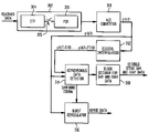
- FIG. 3 illustrates an exemplary readback channel in which the invention may be implemented
- FIG. 4 shows a process flow in an implementation of the invention.
- an asynchronous detection algorithm is used to detect the SAM data.
- an asynchronous detection algorithm employs a bank of seven interpolators along with a synchronously sampled analog/digital converter (ADC) output to perform asynchronous detection of the SAM data.
- the interpolators provide a series of outputs that are successively 1 ⁇ 8 clock cycle digitally phase-shifted from the ADC output.
- the SAM data may be identified on any of these outputs. While the SAM data detection is not synchronous, the burst demodulation operation remains synchronous.
- [s( 1 ) s( 2 ) s( 3 ) . . . s(L)] denotes the L-bit pattern used for the SAM, where each s(.) is either a “0” or a “1”.
- a wide biphase code encodes, for example, a “0” to “1100” and a “1” to “0011”.
- a threshold detector is employed to detect wide biphase-encoded information.
- the readback signal exhibits either a positive peak or a negative peak at the codeword boundary (every 4T, for the above exemplary encoding) after equalization to a target partial response.
- processing of a readback signal is accomplished using a synchronous-sampling analog-to-digital converter (ADC) and a plurality of interpolators.
- ADC analog-to-digital converter
- Each interpolator provides an output signal that is phase-shifted from the output of the ADC.
- seven interpolators may be provided.
- eight output signals are provided in this exemplary embodiment. In other embodiments, other numbers of interpolators may be used.
- the phase-shifting may be equal, so that the output signals include one synchronized signal and seven signals successively 1 ⁇ 8 of a clock cycle from another.
- the readback signal includes a servo sector with field data.
- the field data may include a preamble, an encoded servo address mark (SAM), encoded Gray data, a burst demodulation (demod) field, and a repeatable run-out (RRO) field.
- SAM encoded servo address mark
- demod burst demodulation
- RRO repeatable run-out
- the burst demodulation operation will not be synchronized properly if the detected SAM data is, in general, neither on the synchronized output nor on an output that is close in phase to the synchronized output.
- Equalizer 302 may include continuous time filter (CTF) 304 followed, via switch 305 , by discrete-time, finite impulse response (FIR) filter 306 .
- CTF continuous time filter
- FIR finite impulse response
- the equalized waveform is then provided to A/D converter 308 .
- the input to the A/D converter is a T-symbol-rate target-response-equalized analog signal.
- the digital values at the output of the A/D converter are referred to as the y(kT) values, where k is an integer.
- the synchronous, symbol-rate samples from the A/D converter are then interpolated using digital interpolators 312 .
- Seven digital interpolators may be used, although more or fewer may also be used.
- the outputs of digital interpolators 312 are interpolated y values from y(kT+T/8) to y(kT+7T/8).
- the y(kT) samples from the A/D converter and the interpolated y values from the digital interpolators are provided to asynchronous data detector 314 , where the values are processed in an asynchronous manner.
- interpolated values y(kT+T/8) to y(kT+7T/8) are generated after time (k+1)T using (at least) synchronous samples y(kT) and y((k+1)T).
- burst demodulator 316 The output of A/D converter 308 is also provided to burst demodulator 316 .
- the operation of burst demodulator 316 is timed to a signal provided by asynchronous data detector 314 indicating that the SAM data has been found, which signal is referred to as a SAMFOUND signal.
- a SAMFOUND signal is provided to burst demodulator 316 .
- Burst demodulator 316 includes a counter that waits a certain time (e.g., based on the amount of data between the end of SAM field 102 and the beginning of burst demod field 104 in FIG. 1 taking into account the known processing speed of asynchronous data detector 314 ) from receipt of the SAMFOUND signal before starting burst demodulation.
- the output of burst demodulator 316 is demodulated data.
- the output of asynchronous data detector 314 is also provided to block decoder 318 for decoding SAM and Gray data.
- the output of block decoder 318 is decoded servo SAM and Gray data.
- asynchronous data detector 314 the synchronous outputs from ADC 308 and the interpolated outputs from interpolators 312 are received.
- a SAM field is asynchronously detected in the received data, e.g., using the techniques described in the Annarnpedu 3-8 application. In general, the SAM field may be detected as coinciding with any of the synchronous or interpolated samples.
- the time offset between the sample at which the SAM field was detected and the previous synchronous sample is determined. In the exemplary technique in which seven evenly spaced, interpolated samples are generated between each pair of consecutive synchronous samples, the time offset can range from 0 to 7T/8 in T/8 increments.
- the time offset is compared to a specified threshold. If the time offset is less than the specified threshold, then, at step 410 , the SAMFOUND signal is transmitted to burst demodulator 316 right away. Otherwise, the time offset is not less than the specified threshold and, at step 412 , the SAMFOUND signal is delayed and then transmitted to burst demodulator 316 to coincide with the next synchronous sample.
- the specified threshold is set equal to 2T/ 8 . In this case, if the SAM is detected to coincide with synchronous sample y(kT) or the first interpolated sample y(kT+T/8), then the SAMFOUND signal will be sent to burst demodulator 316 right away. Otherwise, the SAMFOUND signal is delayed and then transmitted to coincide with the next synchronous sample.
- Other threshold values are possible.
- the algorithm considers interpolated samples prior to synchronous sample y(kT) as well as those after.
- the time offset calculated in step 406 may be considered to be the absolute value of the difference between synchronous sample y(kT) and the sample at which the SAM is detected. Assuming the previous example of a threshold of 2T/8, if the SAM is detected to coincide with interpolated sample y((k ⁇ 1)T+7T/8), synchronous sample y(kT), or interpolated sample y(kT+T/8), then the SAMFOUND signal will be sent to burst demodulator 316 right away. Otherwise, the SAMFOUND signal is delayed and then transmitted to coincide with the next synchronous sample.
- One way to implement this processing for a threshold of 2T/8 is to examine the triple of samples corresponding to the sample at which the SAM is detected, where the SAM-detected sample is at the middle of the triple, the sample T/8 prior to the SAM-detected sample is at the beginning of the triple, and the sample T/8 after the SAM-detected sample is at the end of the triple.
- the SAMFOUND signal is transmitted right away. Otherwise, the SAMFOUND signal is delayed to coincide with the next synchronous sample.
- a threshold of nT/8 can be implemented using a (2n ⁇ 1)-tuple of samples.
- the present invention may allow for one or more of the following advantages.
- a given implementation allows for synchronization of the demodulation function to asynchronously detected servo address mark data.
- the SAM detection function can be implemented in an asynchronous manner, reducing the problems caused by radial phase incoherence.
- circuit elements may also be implemented in the digital domain as processing steps in a software program.
- Such software may be employed in, for example, a digital signal processor, micro-controller or general-purpose computer.
- the present invention can be embodied in the form of methods and apparatuses for practicing those methods.
- the present invention can also be embodied in the form of program code embodied in tangible media, such as floppy diskettes, CD-ROMs, hard drives, or any other machine-readable storage medium, wherein, when the program code is loaded into and executed by a machine, such as a computer, the machine becomes an apparatus for practicing the invention.
- the present invention can also be embodied in the form of program code, for example, whether stored in a storage medium, loaded into and/or executed by a machine, or transmitted over some transmission medium, such as over electrical wiring or cabling, through fiber optics, or via electromagnetic radiation, wherein, when the program code is loaded into and executed by a machine, such as a computer, the machine becomes an apparatus for practicing the invention.
- program code When implemented on a general-purpose processor, the program code segments combine with the processor to provide a unique device that operates analogously to specific logic circuits.
Landscapes
- Engineering & Computer Science (AREA)
- Signal Processing (AREA)
- Signal Processing For Digital Recording And Reproducing (AREA)
Abstract
Description
Claims (20)
Priority Applications (1)
| Application Number | Priority Date | Filing Date | Title |
|---|---|---|---|
| US11/223,090 US7167328B2 (en) | 2004-12-17 | 2005-09-09 | Synchronizing an asynchronously detected servo signal to synchronous servo demodulation |
Applications Claiming Priority (2)
| Application Number | Priority Date | Filing Date | Title |
|---|---|---|---|
| US63692704P | 2004-12-17 | 2004-12-17 | |
| US11/223,090 US7167328B2 (en) | 2004-12-17 | 2005-09-09 | Synchronizing an asynchronously detected servo signal to synchronous servo demodulation |
Publications (2)
| Publication Number | Publication Date |
|---|---|
| US20060132955A1 US20060132955A1 (en) | 2006-06-22 |
| US7167328B2 true US7167328B2 (en) | 2007-01-23 |
Family
ID=36595390
Family Applications (1)
| Application Number | Title | Priority Date | Filing Date |
|---|---|---|---|
| US11/223,090 Active US7167328B2 (en) | 2004-12-17 | 2005-09-09 | Synchronizing an asynchronously detected servo signal to synchronous servo demodulation |
Country Status (1)
| Country | Link |
|---|---|
| US (1) | US7167328B2 (en) |
Cited By (51)
| Publication number | Priority date | Publication date | Assignee | Title |
|---|---|---|---|---|
| US20070230028A1 (en) * | 2005-01-12 | 2007-10-04 | Kabushiki Kaisha Toshiba | Magnetic recording medium and magnetic recording/reproducing apparatus |
| US20080074778A1 (en) * | 2006-09-22 | 2008-03-27 | Agere Systems Inc. | Systems and Methods for Improving Disk Drive Synchronization |
| US20090052602A1 (en) * | 2007-08-20 | 2009-02-26 | Agere Systems Inc. | Systems and Methods for Improved Timing Recovery |
| US20090052075A1 (en) * | 2007-08-20 | 2009-02-26 | Agere Systems Inc. | Systems and Methods for Improved Synchronization Between an Asynchronously Detected Signal and a Synchronous Operation |
| US20090267819A1 (en) * | 2008-04-29 | 2009-10-29 | Agere Systems Inc. | Systems and Methods for Reducing the Effects of ADC Mismatch |
| US20090268322A1 (en) * | 2008-04-29 | 2009-10-29 | Agere Systems Inc. | Systems and Methods for Acquiring Modified Rate Burst Demodulation in Servo Systems |
| US20090323214A1 (en) * | 2008-06-27 | 2009-12-31 | Agere Systems Inc. | Modulated Disk Lock Clock and Methods for Using Such |
| US20100177430A1 (en) * | 2007-12-14 | 2010-07-15 | George Mathew | Systems and Methods for Fly-Height Control Using Servo Address Mark Data |
| US20100202082A1 (en) * | 2008-07-28 | 2010-08-12 | Nils Graef | Systems and Methods for Variable Fly Height Measurement |
| US20100208377A1 (en) * | 2007-10-30 | 2010-08-19 | Grundvig Jeffrey P | Systems and Methods for Inter-Location Control of Storage Access |
| US20100232046A1 (en) * | 2006-05-01 | 2010-09-16 | Agere Systems Inc. | Methods and Systems for Estimating Time Corresponding to Peak Signal Amplitude |
| US20110002211A1 (en) * | 2009-07-02 | 2011-01-06 | Lsi Corporation | Systems and Methods for Format Efficient Timing Recovery In a Read Channel |
| US20110043938A1 (en) * | 2007-12-14 | 2011-02-24 | George Mathew | Systems and Methods for Fly-Height Control Using Servo Data |
| US20110157737A1 (en) * | 2009-12-31 | 2011-06-30 | Lsi Corporation | Systems and Methods for Detecting a Reference Pattern |
| US8014099B2 (en) | 2007-12-14 | 2011-09-06 | Lsi Corporation | Systems and methods for using an on-the-fly CBD estimate to adjust fly-height |
| US8154972B2 (en) | 2009-06-24 | 2012-04-10 | Lsi Corporation | Systems and methods for hard disk drive data storage including reduced latency loop recovery |
| US8159768B1 (en) | 2008-06-25 | 2012-04-17 | Western Digital Technologies, Inc. | Detecting a servo address mark (SAM) in a servo field sync-up operation |
| US8237597B2 (en) | 2010-09-21 | 2012-08-07 | Lsi Corporation | Systems and methods for semi-independent loop processing |
| US8243381B2 (en) | 2008-11-13 | 2012-08-14 | Agere Systems Inc. | Systems and methods for sector address mark detection |
| US8261171B2 (en) | 2011-01-27 | 2012-09-04 | Lsi Corporation | Systems and methods for diversity combined data detection |
| US8325433B2 (en) | 2011-01-19 | 2012-12-04 | Lsi Corporation | Systems and methods for reduced format data processing |
| US8411383B2 (en) | 2009-07-22 | 2013-04-02 | Lsi Corporation | Systems and methods for high order asymmetry correction |
| US8411385B2 (en) | 2010-12-20 | 2013-04-02 | Lsi Corporation | Systems and methods for improved timing recovery |
| US8498072B2 (en) | 2010-11-29 | 2013-07-30 | Lsi Corporation | Systems and methods for spiral waveform detection |
| US8498071B2 (en) | 2011-06-30 | 2013-07-30 | Lsi Corporation | Systems and methods for inter-track alignment |
| US8526131B2 (en) | 2010-11-29 | 2013-09-03 | Lsi Corporation | Systems and methods for signal polarity determination |
| US8565047B2 (en) | 2011-04-28 | 2013-10-22 | Lsi Corporation | Systems and methods for data write loopback based timing control |
| US8564897B1 (en) | 2012-06-21 | 2013-10-22 | Lsi Corporation | Systems and methods for enhanced sync mark detection |
| US8566381B2 (en) | 2010-08-05 | 2013-10-22 | Lsi Corporation | Systems and methods for sequence detection in data processing |
| US8566378B2 (en) | 2010-09-30 | 2013-10-22 | Lsi Corporation | Systems and methods for retry sync mark detection |
| US8614858B2 (en) | 2010-11-15 | 2013-12-24 | Lsi Corporation | Systems and methods for sync mark detection metric computation |
| US8625216B2 (en) | 2012-06-07 | 2014-01-07 | Lsi Corporation | Servo zone detector |
| US8665544B2 (en) | 2011-05-03 | 2014-03-04 | Lsi Corporation | Systems and methods for servo data detection |
| US8669891B2 (en) | 2011-07-19 | 2014-03-11 | Lsi Corporation | Systems and methods for ADC based timing and gain control |
| US8681444B2 (en) | 2012-06-07 | 2014-03-25 | Lsi Corporation | Multi-zone servo processor |
| US8705673B2 (en) | 2008-09-05 | 2014-04-22 | Lsi Corporation | Timing phase detection using a matched filter set |
| US8749908B2 (en) | 2011-03-17 | 2014-06-10 | Lsi Corporation | Systems and methods for sync mark detection |
| US8773811B2 (en) | 2011-12-12 | 2014-07-08 | Lsi Corporation | Systems and methods for zone servo timing gain recovery |
| US8780476B2 (en) | 2011-09-23 | 2014-07-15 | Lsi Corporation | Systems and methods for controlled wedge spacing in a storage device |
| US8874410B2 (en) | 2011-05-23 | 2014-10-28 | Lsi Corporation | Systems and methods for pattern detection |
| US8949701B2 (en) | 2008-09-23 | 2015-02-03 | Agere Systems Inc. | Systems and methods for low latency media defect detection |
| US8976475B1 (en) | 2013-11-12 | 2015-03-10 | Lsi Corporation | Systems and methods for large sector dynamic format insertion |
| US9019641B2 (en) | 2012-12-13 | 2015-04-28 | Lsi Corporation | Systems and methods for adaptive threshold pattern detection |
| US9053217B2 (en) | 2013-02-17 | 2015-06-09 | Lsi Corporation | Ratio-adjustable sync mark detection system |
| US9129650B2 (en) | 2013-07-25 | 2015-09-08 | Avago Technologies General Ip (Singapore) Pte. Ltd. | Array-reader based magnetic recording systems with frequency division multiplexing |
| US9129646B2 (en) | 2013-09-07 | 2015-09-08 | Avago Technologies General Ip (Singapore) Pte. Ltd. | Array-reader based magnetic recording systems with mixed synchronization |
| US9196297B2 (en) | 2013-03-14 | 2015-11-24 | Avago Technologies General Ip (Singapore) Pte. Ltd. | Systems and methods for enhanced sync mark mis-detection protection |
| US9224420B1 (en) | 2014-10-02 | 2015-12-29 | Avago Technologies General Ip (Singapore) Pte. Ltd. | Syncmark detection failure recovery system |
| US9275655B2 (en) | 2013-06-11 | 2016-03-01 | Avago Technologies General Ip (Singapore) Pte. Ltd. | Timing error detector with diversity loop detector decision feedback |
| US9305581B2 (en) | 2008-12-04 | 2016-04-05 | Avago Technologies General Ip (Singapore) Pte. Ltd. | Systems and methods for memory efficient repeatable run out processing |
| US10152999B2 (en) | 2013-07-03 | 2018-12-11 | Avago Technologies International Sales Pte. Limited | Systems and methods for correlation based data alignment |
Families Citing this family (3)
| Publication number | Priority date | Publication date | Assignee | Title |
|---|---|---|---|---|
| GB0421930D0 (en) * | 2004-10-01 | 2004-11-03 | Nokia Corp | Signal receiver |
| US7831004B2 (en) * | 2006-06-13 | 2010-11-09 | Panasonic Corporation | Synchronous detecting circuit |
| EP3703269B1 (en) * | 2019-02-26 | 2022-06-08 | Nxp B.V. | Phase alignment of a controller clock to a field |
Citations (8)
| Publication number | Priority date | Publication date | Assignee | Title |
|---|---|---|---|---|
| US5835295A (en) | 1996-11-18 | 1998-11-10 | Cirrus Logice, Inc. | Zero phase restart interpolated timing recovery in a sampled amplitude read channel |
| EP1274071A2 (en) | 2001-06-28 | 2003-01-08 | STMicroelectronics, Inc. | Servo circuit having a synchronous servo channel and method for synchronously recovering servo data |
| US6530060B1 (en) | 2000-02-08 | 2003-03-04 | Cirrus Logic, Inc. | Sampled amplitude read channel employing a post processor with a boundary error compensator which compensates for boundary error events in a split-field data sector |
| US20030215036A1 (en) * | 2002-05-20 | 2003-11-20 | Ching-Wen Ma | Timing recovery circuit |
| US6657802B1 (en) | 1999-04-16 | 2003-12-02 | Infineon Technologies Corporation | Phase assisted synchronization detector |
| US20040136477A1 (en) | 2003-01-14 | 2004-07-15 | Viswanath Annampedu | Asynchronous servo RRO detection employing interpolation |
| US6810485B2 (en) * | 2001-01-04 | 2004-10-26 | Maxtor Corporation | Determining the timing of a data signal |
| US6816328B2 (en) * | 2000-06-20 | 2004-11-09 | Infineon Technologies North America Corp. | Pseudo-synchronous interpolated timing recovery for a sampled amplitude read channel |
-
2005
- 2005-09-09 US US11/223,090 patent/US7167328B2/en active Active
Patent Citations (8)
| Publication number | Priority date | Publication date | Assignee | Title |
|---|---|---|---|---|
| US5835295A (en) | 1996-11-18 | 1998-11-10 | Cirrus Logice, Inc. | Zero phase restart interpolated timing recovery in a sampled amplitude read channel |
| US6657802B1 (en) | 1999-04-16 | 2003-12-02 | Infineon Technologies Corporation | Phase assisted synchronization detector |
| US6530060B1 (en) | 2000-02-08 | 2003-03-04 | Cirrus Logic, Inc. | Sampled amplitude read channel employing a post processor with a boundary error compensator which compensates for boundary error events in a split-field data sector |
| US6816328B2 (en) * | 2000-06-20 | 2004-11-09 | Infineon Technologies North America Corp. | Pseudo-synchronous interpolated timing recovery for a sampled amplitude read channel |
| US6810485B2 (en) * | 2001-01-04 | 2004-10-26 | Maxtor Corporation | Determining the timing of a data signal |
| EP1274071A2 (en) | 2001-06-28 | 2003-01-08 | STMicroelectronics, Inc. | Servo circuit having a synchronous servo channel and method for synchronously recovering servo data |
| US20030215036A1 (en) * | 2002-05-20 | 2003-11-20 | Ching-Wen Ma | Timing recovery circuit |
| US20040136477A1 (en) | 2003-01-14 | 2004-07-15 | Viswanath Annampedu | Asynchronous servo RRO detection employing interpolation |
Cited By (79)
| Publication number | Priority date | Publication date | Assignee | Title |
|---|---|---|---|---|
| US7298581B2 (en) * | 2005-01-12 | 2007-11-20 | Kabushiki Kaisha Toshiba | Magnetic recording medium and magnetic recording/reproducing apparatus |
| US20070230023A1 (en) * | 2005-01-12 | 2007-10-04 | Kabushiki Kaisha Toshiba | Magnetic recording medium and magnetic recording/reproducing apparatus |
| US7298580B2 (en) * | 2005-01-12 | 2007-11-20 | Kabushiki Kaisha Toshiba | Magnetic recording medium and magnetic recording/reproducing apparatus |
| US7298576B2 (en) * | 2005-01-12 | 2007-11-20 | Kabushiki Kaisha Toshiba | Magnetic recording medium and magnetic recording/reproducing apparatus |
| US20070230031A1 (en) * | 2005-01-12 | 2007-10-04 | Kabushiki Kaisha Toshiba | Magnetic recording medium and magnetic recording/reproducing apparatus |
| US20070236824A1 (en) * | 2005-01-12 | 2007-10-11 | Kabushiki Kaisha Toshiba | Magnetic recording medium and magnetic recording/reproducing apparatus |
| US20070236823A1 (en) * | 2005-01-12 | 2007-10-11 | Kabushiki Kaisha Toshiba | Magnetic recording medium and magnetic recording/reproducing apparatus |
| US7298577B2 (en) * | 2005-01-12 | 2007-11-20 | Kabushiki Kaisha Toshiba | Magnetic recording medium and magnetic recording/reproducing apparatus |
| US20070230028A1 (en) * | 2005-01-12 | 2007-10-04 | Kabushiki Kaisha Toshiba | Magnetic recording medium and magnetic recording/reproducing apparatus |
| US20070230029A1 (en) * | 2005-01-12 | 2007-10-04 | Kabushiki Kaisha Toshiba | Magnetic recording medium and magnetic recording/reproducing apparatus |
| US20070230032A1 (en) * | 2005-01-12 | 2007-10-04 | Kabushiki Kaisha Toshiba | Magnetic recording medium and magnetic recording/reproducing apparatus |
| US7298579B2 (en) * | 2005-01-12 | 2007-11-20 | Kabushiki Kaisha Toshiba | Magnetic recording medium and magnetic recording/reproducing apparatus |
| US7298578B2 (en) * | 2005-01-12 | 2007-11-20 | Kabushiki Kaisha Toshiba | Magnetic recording medium and magnetic recording/reproducing apparatus |
| US7298582B2 (en) * | 2005-01-12 | 2007-11-20 | Kabushiki Kaisha Toshiba | Magnetic recording medium and magnetic recording/reproducing apparatus |
| US8059349B2 (en) | 2006-05-01 | 2011-11-15 | Agere Systems Inc. | Methods and systems for estimating time corresponding to peak signal amplitude |
| US20100232046A1 (en) * | 2006-05-01 | 2010-09-16 | Agere Systems Inc. | Methods and Systems for Estimating Time Corresponding to Peak Signal Amplitude |
| US20080074778A1 (en) * | 2006-09-22 | 2008-03-27 | Agere Systems Inc. | Systems and Methods for Improving Disk Drive Synchronization |
| US7499238B2 (en) | 2006-09-22 | 2009-03-03 | Agere Systems Inc. | Systems and methods for improving disk drive synchronization |
| US20090052075A1 (en) * | 2007-08-20 | 2009-02-26 | Agere Systems Inc. | Systems and Methods for Improved Synchronization Between an Asynchronously Detected Signal and a Synchronous Operation |
| US8254049B2 (en) | 2007-08-20 | 2012-08-28 | Agere Systems Inc. | Systems and methods for improved synchronization between an asynchronously detected signal and a synchronous operation |
| US8054931B2 (en) | 2007-08-20 | 2011-11-08 | Agere Systems Inc. | Systems and methods for improved timing recovery |
| US20090052602A1 (en) * | 2007-08-20 | 2009-02-26 | Agere Systems Inc. | Systems and Methods for Improved Timing Recovery |
| US20100208377A1 (en) * | 2007-10-30 | 2010-08-19 | Grundvig Jeffrey P | Systems and Methods for Inter-Location Control of Storage Access |
| US8174784B2 (en) | 2007-10-30 | 2012-05-08 | Agere Systems Inc. | Systems and methods for inter-location control of storage access |
| US8154818B2 (en) | 2007-12-14 | 2012-04-10 | Lsi Corporation | Systems and methods for adaptive CBD estimation in a storage device |
| US9305582B2 (en) | 2007-12-14 | 2016-04-05 | Avago Technologies General Ip (Singapore) Pte. Ltd. | Systems and methods for fly-height control using servo data |
| US20100177430A1 (en) * | 2007-12-14 | 2010-07-15 | George Mathew | Systems and Methods for Fly-Height Control Using Servo Address Mark Data |
| US8054573B2 (en) | 2007-12-14 | 2011-11-08 | Lsi Corporation | Systems and methods for fly-height control using servo address mark data |
| US8014099B2 (en) | 2007-12-14 | 2011-09-06 | Lsi Corporation | Systems and methods for using an on-the-fly CBD estimate to adjust fly-height |
| US20110043938A1 (en) * | 2007-12-14 | 2011-02-24 | George Mathew | Systems and Methods for Fly-Height Control Using Servo Data |
| US7768437B2 (en) | 2008-04-29 | 2010-08-03 | Agere Systems Inc. | Systems and methods for reducing the effects of ADC mismatch |
| US7813065B2 (en) | 2008-04-29 | 2010-10-12 | Agere Systems Inc. | Systems and methods for acquiring modified rate burst demodulation in servo systems |
| US20090267819A1 (en) * | 2008-04-29 | 2009-10-29 | Agere Systems Inc. | Systems and Methods for Reducing the Effects of ADC Mismatch |
| US20090268322A1 (en) * | 2008-04-29 | 2009-10-29 | Agere Systems Inc. | Systems and Methods for Acquiring Modified Rate Burst Demodulation in Servo Systems |
| US8159768B1 (en) | 2008-06-25 | 2012-04-17 | Western Digital Technologies, Inc. | Detecting a servo address mark (SAM) in a servo field sync-up operation |
| US7929237B2 (en) | 2008-06-27 | 2011-04-19 | Agere Systems Inc. | Modulated disk lock clock and methods for using such |
| US20090323214A1 (en) * | 2008-06-27 | 2009-12-31 | Agere Systems Inc. | Modulated Disk Lock Clock and Methods for Using Such |
| US8098451B2 (en) | 2008-07-28 | 2012-01-17 | Agere Systems Inc. | Systems and methods for variable fly height measurement |
| US20100202082A1 (en) * | 2008-07-28 | 2010-08-12 | Nils Graef | Systems and Methods for Variable Fly Height Measurement |
| US8705673B2 (en) | 2008-09-05 | 2014-04-22 | Lsi Corporation | Timing phase detection using a matched filter set |
| US8949701B2 (en) | 2008-09-23 | 2015-02-03 | Agere Systems Inc. | Systems and methods for low latency media defect detection |
| US8243381B2 (en) | 2008-11-13 | 2012-08-14 | Agere Systems Inc. | Systems and methods for sector address mark detection |
| US9305581B2 (en) | 2008-12-04 | 2016-04-05 | Avago Technologies General Ip (Singapore) Pte. Ltd. | Systems and methods for memory efficient repeatable run out processing |
| US8154972B2 (en) | 2009-06-24 | 2012-04-10 | Lsi Corporation | Systems and methods for hard disk drive data storage including reduced latency loop recovery |
| US20110002211A1 (en) * | 2009-07-02 | 2011-01-06 | Lsi Corporation | Systems and Methods for Format Efficient Timing Recovery In a Read Channel |
| US8174949B2 (en) | 2009-07-02 | 2012-05-08 | Lsi Corporation | Systems and methods for format efficient timing recovery in a read channel |
| US8411383B2 (en) | 2009-07-22 | 2013-04-02 | Lsi Corporation | Systems and methods for high order asymmetry correction |
| US20110157737A1 (en) * | 2009-12-31 | 2011-06-30 | Lsi Corporation | Systems and Methods for Detecting a Reference Pattern |
| US8456775B2 (en) | 2009-12-31 | 2013-06-04 | Lsi Corporation | Systems and methods for detecting a reference pattern |
| US8566381B2 (en) | 2010-08-05 | 2013-10-22 | Lsi Corporation | Systems and methods for sequence detection in data processing |
| US8237597B2 (en) | 2010-09-21 | 2012-08-07 | Lsi Corporation | Systems and methods for semi-independent loop processing |
| US8566378B2 (en) | 2010-09-30 | 2013-10-22 | Lsi Corporation | Systems and methods for retry sync mark detection |
| US8614858B2 (en) | 2010-11-15 | 2013-12-24 | Lsi Corporation | Systems and methods for sync mark detection metric computation |
| US8526131B2 (en) | 2010-11-29 | 2013-09-03 | Lsi Corporation | Systems and methods for signal polarity determination |
| US8498072B2 (en) | 2010-11-29 | 2013-07-30 | Lsi Corporation | Systems and methods for spiral waveform detection |
| US8411385B2 (en) | 2010-12-20 | 2013-04-02 | Lsi Corporation | Systems and methods for improved timing recovery |
| US8325433B2 (en) | 2011-01-19 | 2012-12-04 | Lsi Corporation | Systems and methods for reduced format data processing |
| US8261171B2 (en) | 2011-01-27 | 2012-09-04 | Lsi Corporation | Systems and methods for diversity combined data detection |
| US8749908B2 (en) | 2011-03-17 | 2014-06-10 | Lsi Corporation | Systems and methods for sync mark detection |
| US8565047B2 (en) | 2011-04-28 | 2013-10-22 | Lsi Corporation | Systems and methods for data write loopback based timing control |
| US8760977B2 (en) | 2011-04-28 | 2014-06-24 | Lsi Corporation | Systems and methods for data write loopback based timing control |
| US8665544B2 (en) | 2011-05-03 | 2014-03-04 | Lsi Corporation | Systems and methods for servo data detection |
| US8874410B2 (en) | 2011-05-23 | 2014-10-28 | Lsi Corporation | Systems and methods for pattern detection |
| US8498071B2 (en) | 2011-06-30 | 2013-07-30 | Lsi Corporation | Systems and methods for inter-track alignment |
| US8669891B2 (en) | 2011-07-19 | 2014-03-11 | Lsi Corporation | Systems and methods for ADC based timing and gain control |
| US8780476B2 (en) | 2011-09-23 | 2014-07-15 | Lsi Corporation | Systems and methods for controlled wedge spacing in a storage device |
| US8773811B2 (en) | 2011-12-12 | 2014-07-08 | Lsi Corporation | Systems and methods for zone servo timing gain recovery |
| US8625216B2 (en) | 2012-06-07 | 2014-01-07 | Lsi Corporation | Servo zone detector |
| US8681444B2 (en) | 2012-06-07 | 2014-03-25 | Lsi Corporation | Multi-zone servo processor |
| US8564897B1 (en) | 2012-06-21 | 2013-10-22 | Lsi Corporation | Systems and methods for enhanced sync mark detection |
| US9019641B2 (en) | 2012-12-13 | 2015-04-28 | Lsi Corporation | Systems and methods for adaptive threshold pattern detection |
| US9053217B2 (en) | 2013-02-17 | 2015-06-09 | Lsi Corporation | Ratio-adjustable sync mark detection system |
| US9196297B2 (en) | 2013-03-14 | 2015-11-24 | Avago Technologies General Ip (Singapore) Pte. Ltd. | Systems and methods for enhanced sync mark mis-detection protection |
| US9275655B2 (en) | 2013-06-11 | 2016-03-01 | Avago Technologies General Ip (Singapore) Pte. Ltd. | Timing error detector with diversity loop detector decision feedback |
| US10152999B2 (en) | 2013-07-03 | 2018-12-11 | Avago Technologies International Sales Pte. Limited | Systems and methods for correlation based data alignment |
| US9129650B2 (en) | 2013-07-25 | 2015-09-08 | Avago Technologies General Ip (Singapore) Pte. Ltd. | Array-reader based magnetic recording systems with frequency division multiplexing |
| US9129646B2 (en) | 2013-09-07 | 2015-09-08 | Avago Technologies General Ip (Singapore) Pte. Ltd. | Array-reader based magnetic recording systems with mixed synchronization |
| US8976475B1 (en) | 2013-11-12 | 2015-03-10 | Lsi Corporation | Systems and methods for large sector dynamic format insertion |
| US9224420B1 (en) | 2014-10-02 | 2015-12-29 | Avago Technologies General Ip (Singapore) Pte. Ltd. | Syncmark detection failure recovery system |
Also Published As
| Publication number | Publication date |
|---|---|
| US20060132955A1 (en) | 2006-06-22 |
Similar Documents
| Publication | Publication Date | Title |
|---|---|---|
| US7167328B2 (en) | Synchronizing an asynchronously detected servo signal to synchronous servo demodulation | |
| JP4602694B2 (en) | Maximum likelihood detection of asynchronous servo data using interpolation | |
| US8254049B2 (en) | Systems and methods for improved synchronization between an asynchronously detected signal and a synchronous operation | |
| US7092462B2 (en) | Asynchronous servo RRO detection employing interpolation | |
| US7002767B2 (en) | Detection of recorded data employing interpolation with gain compensation | |
| US7082005B2 (en) | Servo data detection in the presence or absence of radial incoherence using digital interpolators | |
| US8174949B2 (en) | Systems and methods for format efficient timing recovery in a read channel | |
| US7813065B2 (en) | Systems and methods for acquiring modified rate burst demodulation in servo systems | |
| JP5011429B2 (en) | Servo data processing including DC level shift | |
| US8411385B2 (en) | Systems and methods for improved timing recovery | |
| US9305581B2 (en) | Systems and methods for memory efficient repeatable run out processing | |
| JP2004522240A (en) | Servo data detection method and detection device with improved tolerance to phase shift | |
| US8049982B1 (en) | Methods and apparatus for measuring servo address mark distance in a read channel using selective fine phase estimate | |
| US6760173B2 (en) | Synchronization servo mark detector and method having improved phase error immunity for use in mass data storage device, or the like | |
| US7502187B2 (en) | Address mark detection | |
| EP1566806A1 (en) | Data reproducing apparatus having phase difference corrector and data head detector | |
| US20060023332A1 (en) | Method for using a minimum latency loop for a synchronization system in a hard disk drive | |
| KR20010078376A (en) | Averaged sample decisions for preamble detection | |
| JPH10334601A (en) | Reproducer for digital signal | |
| JPH11273264A (en) | Reproduced data detecting device and reproduced data detecting method |
Legal Events
| Date | Code | Title | Description |
|---|---|---|---|
| AS | Assignment |
Owner name: AGERE SYSTEMS INC., PENNSYLVANIA Free format text: ASSIGNMENT OF ASSIGNORS INTEREST;ASSIGNORS:ANNAMPEDU, VISWANATH;AZIZ, PERVEZ M.;REEL/FRAME:016991/0615;SIGNING DATES FROM 20050823 TO 20050907 |
|
| STCF | Information on status: patent grant |
Free format text: PATENTED CASE |
|
| FPAY | Fee payment |
Year of fee payment: 4 |
|
| FPAY | Fee payment |
Year of fee payment: 8 |
|
| AS | Assignment |
Owner name: AGERE SYSTEMS LLC, PENNSYLVANIA Free format text: CERTIFICATE OF CONVERSION;ASSIGNOR:AGERE SYSTEMS INC.;REEL/FRAME:033663/0948 Effective date: 20120730 |
|
| AS | Assignment |
Owner name: AVAGO TECHNOLOGIES GENERAL IP (SINGAPORE) PTE. LTD Free format text: ASSIGNMENT OF ASSIGNORS INTEREST;ASSIGNOR:AGERE SYSTEMS LLC;REEL/FRAME:035365/0634 Effective date: 20140804 |
|
| AS | Assignment |
Owner name: BANK OF AMERICA, N.A., AS COLLATERAL AGENT, NORTH CAROLINA Free format text: PATENT SECURITY AGREEMENT;ASSIGNOR:AVAGO TECHNOLOGIES GENERAL IP (SINGAPORE) PTE. LTD.;REEL/FRAME:037808/0001 Effective date: 20160201 Owner name: BANK OF AMERICA, N.A., AS COLLATERAL AGENT, NORTH Free format text: PATENT SECURITY AGREEMENT;ASSIGNOR:AVAGO TECHNOLOGIES GENERAL IP (SINGAPORE) PTE. LTD.;REEL/FRAME:037808/0001 Effective date: 20160201 |
|
| AS | Assignment |
Owner name: AVAGO TECHNOLOGIES GENERAL IP (SINGAPORE) PTE. LTD., SINGAPORE Free format text: TERMINATION AND RELEASE OF SECURITY INTEREST IN PATENTS;ASSIGNOR:BANK OF AMERICA, N.A., AS COLLATERAL AGENT;REEL/FRAME:041710/0001 Effective date: 20170119 Owner name: AVAGO TECHNOLOGIES GENERAL IP (SINGAPORE) PTE. LTD Free format text: TERMINATION AND RELEASE OF SECURITY INTEREST IN PATENTS;ASSIGNOR:BANK OF AMERICA, N.A., AS COLLATERAL AGENT;REEL/FRAME:041710/0001 Effective date: 20170119 |
|
| MAFP | Maintenance fee payment |
Free format text: PAYMENT OF MAINTENANCE FEE, 12TH YEAR, LARGE ENTITY (ORIGINAL EVENT CODE: M1553) Year of fee payment: 12 |
|
| AS | Assignment |
Owner name: AVAGO TECHNOLOGIES INTERNATIONAL SALES PTE. LIMITE Free format text: MERGER;ASSIGNOR:AVAGO TECHNOLOGIES GENERAL IP (SINGAPORE) PTE. LTD.;REEL/FRAME:047196/0097 Effective date: 20180509 |
|
| AS | Assignment |
Owner name: AVAGO TECHNOLOGIES INTERNATIONAL SALES PTE. LIMITE Free format text: CORRECTIVE ASSIGNMENT TO CORRECT THE EXECUTION DATE PREVIOUSLY RECORDED AT REEL: 047196 FRAME: 0097. ASSIGNOR(S) HEREBY CONFIRMS THE MERGER;ASSIGNOR:AVAGO TECHNOLOGIES GENERAL IP (SINGAPORE) PTE. LTD.;REEL/FRAME:048555/0510 Effective date: 20180905 |
|
| AS | Assignment |
Owner name: BROADCOM INTERNATIONAL PTE. LTD., SINGAPORE Free format text: ASSIGNMENT OF ASSIGNORS INTEREST;ASSIGNOR:AVAGO TECHNOLOGIES INTERNATIONAL SALES PTE. LIMITED;REEL/FRAME:053771/0901 Effective date: 20200826 |
|
| AS | Assignment |
Owner name: AVAGO TECHNOLOGIES INTERNATIONAL SALES PTE. LIMITED, SINGAPORE Free format text: MERGER;ASSIGNORS:AVAGO TECHNOLOGIES INTERNATIONAL SALES PTE. LIMITED;BROADCOM INTERNATIONAL PTE. LTD.;REEL/FRAME:062952/0850 Effective date: 20230202 |