US7160690B2 - Nitrate sensor - Google Patents
Nitrate sensor Download PDFInfo
- Publication number
- US7160690B2 US7160690B2 US10/290,108 US29010802A US7160690B2 US 7160690 B2 US7160690 B2 US 7160690B2 US 29010802 A US29010802 A US 29010802A US 7160690 B2 US7160690 B2 US 7160690B2
- Authority
- US
- United States
- Prior art keywords
- nitrate
- mpt
- fluorescence
- domain
- emitter
- Prior art date
- Legal status (The legal status is an assumption and is not a legal conclusion. Google has not performed a legal analysis and makes no representation as to the accuracy of the status listed.)
- Expired - Fee Related, expires
Links
Images


Classifications
-
- C—CHEMISTRY; METALLURGY
- C12—BIOCHEMISTRY; BEER; SPIRITS; WINE; VINEGAR; MICROBIOLOGY; ENZYMOLOGY; MUTATION OR GENETIC ENGINEERING
- C12Q—MEASURING OR TESTING PROCESSES INVOLVING ENZYMES, NUCLEIC ACIDS OR MICROORGANISMS; COMPOSITIONS OR TEST PAPERS THEREFOR; PROCESSES OF PREPARING SUCH COMPOSITIONS; CONDITION-RESPONSIVE CONTROL IN MICROBIOLOGICAL OR ENZYMOLOGICAL PROCESSES
- C12Q1/00—Measuring or testing processes involving enzymes, nucleic acids or microorganisms; Compositions therefor; Processes of preparing such compositions
- C12Q1/26—Measuring or testing processes involving enzymes, nucleic acids or microorganisms; Compositions therefor; Processes of preparing such compositions involving oxidoreductase
-
- G—PHYSICS
- G01—MEASURING; TESTING
- G01N—INVESTIGATING OR ANALYSING MATERIALS BY DETERMINING THEIR CHEMICAL OR PHYSICAL PROPERTIES
- G01N21/00—Investigating or analysing materials by the use of optical means, i.e. using sub-millimetre waves, infrared, visible or ultraviolet light
- G01N21/62—Systems in which the material investigated is excited whereby it emits light or causes a change in wavelength of the incident light
- G01N21/63—Systems in which the material investigated is excited whereby it emits light or causes a change in wavelength of the incident light optically excited
- G01N21/64—Fluorescence; Phosphorescence
- G01N21/6428—Measuring fluorescence of fluorescent products of reactions or of fluorochrome labelled reactive substances, e.g. measuring quenching effects, using measuring "optrodes"
-
- G—PHYSICS
- G01—MEASURING; TESTING
- G01N—INVESTIGATING OR ANALYSING MATERIALS BY DETERMINING THEIR CHEMICAL OR PHYSICAL PROPERTIES
- G01N33/00—Investigating or analysing materials by specific methods not covered by groups G01N1/00 - G01N31/00
- G01N33/48—Biological material, e.g. blood, urine; Haemocytometers
- G01N33/50—Chemical analysis of biological material, e.g. blood, urine; Testing involving biospecific ligand binding methods; Immunological testing
- G01N33/84—Chemical analysis of biological material, e.g. blood, urine; Testing involving biospecific ligand binding methods; Immunological testing involving inorganic compounds or pH
-
- G—PHYSICS
- G01—MEASURING; TESTING
- G01N—INVESTIGATING OR ANALYSING MATERIALS BY DETERMINING THEIR CHEMICAL OR PHYSICAL PROPERTIES
- G01N21/00—Investigating or analysing materials by the use of optical means, i.e. using sub-millimetre waves, infrared, visible or ultraviolet light
- G01N21/62—Systems in which the material investigated is excited whereby it emits light or causes a change in wavelength of the incident light
- G01N21/63—Systems in which the material investigated is excited whereby it emits light or causes a change in wavelength of the incident light optically excited
- G01N21/64—Fluorescence; Phosphorescence
- G01N21/6428—Measuring fluorescence of fluorescent products of reactions or of fluorochrome labelled reactive substances, e.g. measuring quenching effects, using measuring "optrodes"
- G01N2021/6432—Quenching
-
- G—PHYSICS
- G01—MEASURING; TESTING
- G01N—INVESTIGATING OR ANALYSING MATERIALS BY DETERMINING THEIR CHEMICAL OR PHYSICAL PROPERTIES
- G01N21/00—Investigating or analysing materials by the use of optical means, i.e. using sub-millimetre waves, infrared, visible or ultraviolet light
- G01N21/17—Systems in which incident light is modified in accordance with the properties of the material investigated
- G01N21/25—Colour; Spectral properties, i.e. comparison of effect of material on the light at two or more different wavelengths or wavelength bands
- G01N21/27—Colour; Spectral properties, i.e. comparison of effect of material on the light at two or more different wavelengths or wavelength bands using photo-electric detection ; circuits for computing concentration
- G01N21/274—Calibration, base line adjustment, drift correction
-
- Y—GENERAL TAGGING OF NEW TECHNOLOGICAL DEVELOPMENTS; GENERAL TAGGING OF CROSS-SECTIONAL TECHNOLOGIES SPANNING OVER SEVERAL SECTIONS OF THE IPC; TECHNICAL SUBJECTS COVERED BY FORMER USPC CROSS-REFERENCE ART COLLECTIONS [XRACs] AND DIGESTS
- Y10—TECHNICAL SUBJECTS COVERED BY FORMER USPC
- Y10T—TECHNICAL SUBJECTS COVERED BY FORMER US CLASSIFICATION
- Y10T436/00—Chemistry: analytical and immunological testing
- Y10T436/17—Nitrogen containing
- Y10T436/173076—Nitrite or nitrate
Definitions
- This invention relates generally to biosensors; and more particularly to a biosensor method for detecting nitrate based on the fluorescence properties of a receptor molecule and a biosensor apparatus containing the active-site fragment of the receptor molecule for detecting nitrate.
- Nitrate ion from fertilizers and treated sewage has reached disquietingly high concentrations in water supplies all around the world.
- the Environmental Protection Agency EPA
- EPA Environmental Protection Agency
- NO 3 —N NO 3 ⁇ nitrogen
- the health and environmental risks associated with elevated nitrate levels are the following:
- nitrate contamination of source water will always be a concern for industries that depend on water purity for the manufacturing of their finished product.
- the data related to nitrate as a contaminant demonstrates the scope of the problem:
- kits for measuring nitrate there are a number of commercially available kits for measuring nitrate. These kits utilize a variety of sensing technologies.
- the EPA Office of Ground Water and Drinking Water maintains a database of approved analytical methods for drinking water compliance monitoring.
- the methods currently approved for monitoring nitrates are cadmium reduction, ion chromatography and ion-specific electrodes. It is our belief that none of these approaches provides a measurement technology that is rugged, sensitive and suited to the broad spectrum of water sources that need to be monitored.
- the most sensitive devices, such as ion chromatography are not portable or adaptable for field-testing without shipping the samples. While many of the field test kits are portable they introduce the opportunity for operator error, in terms of mixing the reagents and interpreting the results.
- a survey of current nitrate detection technologies is presented in FIG. 22 .
- SDWA Safe Drinking Water Act
- USEPA United States Environmental Protection Agency
- Effective monitoring is a critical component for providing clean, safe drinking water and protecting our water resources.
- the technology associated with water monitoring must be upgraded to meet the needs of the water and wastewater industries.
- sensors based upon biological sensing elements have been developed and exploited for detecting and quantifying a broad range of analytes from ions, metals, and small organics to proteins, lipids, nucleic acids and even whole organisms.
- These elements include enzymes, antibodies, RNA/DNA probes, membrane channels, whole cells, organs and even whole multicellular organisms.
- biosensors in that the sensing element is of biological origin.
- Biosensors are monitoring devices composed of two elements, the first of which is the signal capture component that uses a biological entity such as an enzyme, antibody or cell surface receptor. The second part is the signal transduction element that converts the biological response into a measurable signal like fluorescence, electric current or potential. Biosensors have been described for the determination of more than thirty different environmentally relevant compounds (Riedel, 1998).
- Biosensors can achieve the same or greater selectivity and sensitivity as analytical methods, and many allow detection and/or quantification in the absence of reagents and sample preparation, and most often do not require a skilled operator. Because the sensing element in a biosensor is typically very small and because detection is based upon molecular recognition of individual ligand molecules, biosensor devices can be very small and portable, thereby greatly expanding the utility and application of sensing and monitoring technologies.
- Biosensors for a broad range of analytes including environmental contaminants and analytes relevant to industrial processes, medical diagnostics and law enforcement have been reported in the scientific and patent literature, though only a few technologies have obtained commercial success to date. See Riedel, K., 1998, in Ramsay, G. [ed.] Commercial Biosensors, Vol. 148, Chemical Analysis, John Wiley & Sons, New York, pp. 267–294; Kress-Rogers, E. 1997, Handbook of Biosensors and Electronic Noses: Medicine, Food, and the Environment, [ed., Kress-Rogers, E.], CRC Press, Boca Raton; Scheller, F. W. and Pfeiffer, D. 1997, in id; Urban, G. 1997 in id.
- Nitrate reductase an oxidoreductase, from a variety of sources (bacteria, fungi, and vascular plants) has been used to assay nitrate in environmental or medical samples, in biosensor applications and in bioremediation applications.
- Nitrate reductases from different eukaryotic genera (yeast, algae, vascular plants) all share a common subunit structure and a catalytic function—the reduction of nitrate (NO3 ⁇ ) to nitrite (NO2 ⁇ ).
- NO3 ⁇ nitrate
- NO2 ⁇ nitrite
- the Faradic current derived from the redox reaction at the electrode is measured.
- Glazier, S. A., Campbell, E. R. and Campbell, W. H. (1998, Anal. Chem. 70:1511–1515) generated an NR-based nitrate sensor that exploits a vascular plant (corn) NR and glassy carbon electrodes for the measurement of nitrate in buffered solutions.
- Amperometric biosensors have been developed to take advantage of the redox properties of enzymes.
- the enzymes may be maintained in solution on the surface of the electrode by using a semi permeable membrane, or they may be immobilized onto the surface of the electrode either covalently through some cross-linking chemistry or entrapped in a cross-linked matrix which adheres to the surface of the electrode.
- the matrix may be a protein or sol-gel, while in other it may be a conducting polymer that can serve to provide and enhance the electrical continuum between the redox centers of the enzyme and the electrode.
- the enzyme activity was coupled to a glassy carbon electrode for amperometric assessment of nitrate levels in buffered solutions and in buffered natural water samples.
- NR was “wired” with alkylpyrroleviologen-based redox polymers
- enzyme activity was low. More recently, it has been demonstrated that such redox polymers and even the monomers in solution strongly (>90% loss of activity) inactivate NR (Ramsay and Wolpert, 1999, Anal. Chem. 71:504–506
- Enzyme-based amperometric sensors generally suffer from several major limitations: 1) traditional methods of electrode preparation with each of the three electrode cells comprised of different materials make modeled performances difficult to derive, 2) insufficient enzyme availability/high cost of enzyme preparation, 3) instability of enzyme and/or mediators under ambient conditions, 4) inadequate transducers for reporting enzyme activity, 5) inefficient enzyme immobilization or coupling to electrode, 6) end-product inhibition, and 7) enzyme specificity lacking, 8) a high cost of production and/or multiple steps in preparation.
- the present invention introduces such refinement.
- the invention has at least two independently usable facets or aspects, which will now be introduced.
- the present invention is a biosensor method for detecting nitrate in a test specimen.
- the method includes exposing a fluorescence emitting molecule to a test sample and then measuring any resulting decrease in fluorescence.
- the quantity of nitrate in a test sample can be calculated.
- the nitrate quantity is proportional to the measured decrease in fluorescence.
- the nitrate quenches the fluorescence signal.
- the fluorescence signal comes from a fluorescence emitter which in preferred embodiments of the invention is a component of nitrate reductase.
- the component can be part of a domain region of nitrate reductase—specically, the Molybdenum-Molybdopterin (Mo-MPT)center.
- the Mo-MPT can be obtained by cleaving the Mo-MPT domain of nitrate reductase and filtering the cleavage products to isolate the Mo-MPT.
- the Mo-MPT can be obtained by gene subcloning the fragment. This can be done by inserting a cloned Mo-MPT fragment into bacterial expression vectors, identifying vectors which screen positive for the insertion and then isolating the Mo-MPT clone from the those vectors which screened positive.
- the gene subcloning step can be preceded by an amplification step where the Mo-MPT fragment is cleaved from nitrate reductase and is then amplified using polymerase chain reaction and subcloning.
- the measuring step of the method has a nitrate detection sensitivity of one part per billion. In other preferred embodiments, the measuring step of the method has a nitrate detection sensitivity of ten parts per million. Yet, in other preferred embodiments, the measuring step of the method has a nitrate detection sensitivity of one hundred parts per million.
- the biosensor method is very versatile and in particularly preferred embodiments allows immersing the emitter in the test specimen.
- the emitter is disposed on a structural support.
- the structural support may comprise a wall of a chamber, room or passageway.
- the structural support may be any one of a gel matrix, a microsolution, an electrode, a microchip, a fiber optic cable and a solid particle.
- the test specimen may be substantially continuously monitored.
- Application of this method extends to any one of natural natural fresh, marine and estuarine waters, municipal and rural drinking water sources, aqueous solutions associated with wastewater treatment facilities, aqueous solutions associated with industrial process streams, pharmaceuticals, nutritional supplements, foodstuffs, beverages, body fluids, chemicals, water specimens, biologicals, vapors, and derivatives thereof.
- the method of the invention doesn't necessarily require the use of electrodes or preparation of several different enzyme coated electrode materials, unlike many enzyme-based amperometric sensors of the prior art. Also, there is little concern for insufficient availability of an enzyme, since the method of this invention is based on a fragment of an enzyme which can easily be amplified and cloned. Furthermore, the adaptability of this method allows the emitter to be immersed in a test sample or disposed on a variety of substrates, thus there is less concern regarding immobilization techniques or coupling to an electrode. Also, the method is based on commonly used and widely available instrumentation, and as a result it is economical and uncomplicated.
- the invention is a biosensor apparatus for detecting nitrate in a test specimen.
- the apparatus includes an enclosure containing a fluorescence emitter and means for adding the specimen to the enclosure.
- a detector senses the fluorescence of the emitter and measures decrease in the fluorescence after addition of the sample.
- the apparatus includes a processor for receiving information derived from the sensed fluorescence, and means that are responsive to the processor for communicating a corresponding concentration of nitrate in the specimen.
- the apparatus includes a memory device which holding a calibration formula and a portion of the processor receives the derived information and applying it to the calibration formula for calculating the concentration for display.
- the apparatus also includes automatic means for monitoring the displayed concentration and utilization means that are responsive to the monitoring means.
- the utilization means can be selected from any one of an annunciator for alerting an operator to the communicated concentration; automatically controlled robotics; an automatically controlled nitrate injection system; and an automatically controlled lock or other automatic access-control device for enabling or not enabling access to a facility, an apparatus, credit, information, or a service.
- the enclosure can be a sample cell.
- the enclosure can also be a room or passageway.
- the enclosure includes a structure for supporting the emitter. It is particularly preferred that the structure can be selected from any of a gel matrix, a microsolution, an electrode, a microchip, a fiber optics cable, a waveguide or a solid particle.
- this second facet of the invention too adapts to a wide variety of applications and is based on commonly used and widely available instrumentation.
- this facet of the invention promotes and enables the desired economy that accompanies use of a sensitive and easily adaptable biosensor apparatus.
- FIG. 1 is a schematic sequence model of nitrate reductase
- FIGS. 2 a through c are structural diagrams of the Mo-MPT subunit of nitrate reductase, wherein (a) shows its chemical skeletal structure, (b) shows a ball-and-stick model of its structure and (c) shows a space-filling model of its structure, (See W. H. Campbell, Annu. Rev. Plant Physiol. Plant Mol. Biol. 1999, 50, 277–303.);
- FIG. 3 is a schematic showing binding of nitrate and Mo-MPT to a substrate
- FIG. 4 is a schematic showing Mo-MPT disposed on a substrate as it is excited and emits fluorescence signals
- FIG. 5 is a schematic sequence model of nitrate reductase highlighting its three domains
- FIG. 6 is a schematic diagram representing filtration of the cleavage products of nitrate reductase
- FIG. 7 is a graph of data showing the fluorescence excitation and emission profiles of Mo-MPT.
- FIG. 8 is a graph of experimental results showing the fluorescence emission profiles of Mo-MPT quenched by various concentrations of nitrate
- FIG. 9 is a graph of experimental results showing the fluorescence of Mo-MPT at 440 nanometes (nm) quenched by nitrate;
- FIG. 10 is a graph of experimental results comparing fluorescence quenching of Mo-MPT and FAD by nitrate
- FIG. 11 is a picture of an electorphoresis gel confirming the PCR amplification of Mo-MPT gene fragment
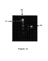
- FIG. 12 is a picture of an electorphoresis gel confirming the positive insertion of sub-cloned Mo-MPT gene fragments into several vectors;
- FIG. 13 is a block diagram showing the sensor applications and embodiments.
- FIG. 14 is a table showing the sensitivity window for nitrate sensor applications.
- biosensor refers to a sensing method for detecting nitrate which comprises binding of nitrate in a test specimen to a fluorescence-signal emitter of the invention.
- Biosensors use catalysis and affinity interactions, generally using agents derived from biological systems or recombinant biological systems. In the present invention, the biosensor uses agents that are derived from such biological systems.
- biosensor also refers to a self-contained analytical device that responds selectively and reversibly to the presence or concentration of nitrate in a test specimen. Accordingly, the device of the present invention comprises a biosensor for practical applications in medicine, chemical monitoring, environmental protection, and process stream monitoring in various industrial applications such as food or beverage processing.
- test specimen is used to refer to a candidate material that might or might not contain nitrate which the methods and device of the invention are detecting.
- nitrate is the chemical entity the methods or device are looking for
- the test specimen is the material in which the methods or device are looking for it.
- fluorescence-signal emitter is a molecule capable of emitting a fluorescence signal.
- the fluorescence-signal emitter may be chemically synthesized or may occur in nature.
- Nitrate assimilation by higher plants, algae, fungi, yeasts and bacteria is significantly more important than nitrogen fixation.
- Nitrate assimilation is achieved by the enzyme nitrate reductase (NR), which reduces nitrate to nitrite (NO 2 ⁇ ). Accordingly, the nitrate reductase enzyme catalyzes the following reaction: NO 3 ⁇ +NADH à NO 2 ⁇ +NAD + +OH ⁇
- nitrate is reduced to nitrite and nicotinamide adenine dinucleotide (NADH) is converted to its oxidized form, NAD + .
- NADH nicotinamide adenine dinucleotide
- the nitrate reductase enzyme is a homodimer containing two identical subunits ranging from 100–145 kDaltons depending on the source organism.
- Each nitrate reductase monomer is composed of three distinct domains; the flavin adenine dinucleotide (FAD) 14 , the heme 12 and molybdenum 9 domains as shown in FIG. 1 . Electrons are transferred through a series of reactions beginning with the FAD region 14 , passing through the heme center 12 and terminating in the molybdenum-containing region 9 .
- FAD flavin adenine dinucleotide
- the active site for nitrate binding and reduction is located in the molybdenum-containing domain 9 as shown in FIG. 1 .
- the other domains shown in FIG. 1 function primarily to donate the electrons that ultimately serve to reduce the nitrate. It has been shown that these other domains are not necessary for the reduction of nitrate to occur, provided that a secondary source of electrons, such as bromo-phenol blue or methyl viologen, is added (Kubo, et al., 1988; Solomonson and Barber, 1990; Mertens et al., 2000)
- FIG. 2 shows the chemical and three-dimensional structures of the molybdenum-containing domain 10 .
- the bacterial nitrate reductases can be classified either as membrane-bound, cytoplasmic or periplasmic according to their cellular location. Sequence comparisons among these three classes reveal some distinctions in their amino acid sequences that are directly related to functional differences among the different nitrate reductase sub-classes (Blasco et al., 1990; Wootton et al., 1991; Berks et al., 1995; Trieber et al., 1996).
- this residue is one of the cysteines (mentioned above) that is involved in binding iron. They discovered, however, that in the E. Coli enzyme, this residue is required to adjust the coordination state of the molybdenum during the reduction reaction cycle (Magalon et al., 1998). Using electron paramagnetic resonance (EPR) they showed that the molybdenum shuttled through coordinations of state 5 and 6 during the reaction.
- EPR electron paramagnetic resonance
- the present invention utilizes these elements of the molybdenum-containing domain 9 to bind nitrate 30 found in unknown test specimens.
- the active site does not need to be chemically reduced to sense nitrate 30 .
- Nitrate 30 is already bound to the molybdenum-molybdopterin (Mo-MPT) center 10 when the it is in oxidized form and so does not need to be reduced to bind nitrate 30 .
- Mo-MPT molybdenum-molybdopterin
- the biosensor method of this invention uses fluorescence detection to sense nitrate 30 levels. Because Mo-MPT 10 naturally fluoresces as shown in FIG. 7 , binding of nitrate 30 can be detected by monitoring the fluorescence signal associated with the Mo-MPT 10 to which it is bound. The Mo-MPT 10 fluorescence signal is quenched by the binding of nitrate 30 . As a result, nitrate 30 can be detected and nitrate 30 levels can be determined by quenching of the fluorescence signal proportionally to the quantity of nitrate present.
- FIG. 8 shows a graph of the experimental results revealing the sensitivity of the method. The data shows detection of nitrate 30 levels as low as 0.3 parts per million (ppm) using this method.
- Such a highly sensitive biosensor method or device has the advantage of being able to monitor minute amounts of nitrate 30 in applications such as those in the medical field which require detection of parts per million (ppm) concentrations of nitrate in urine and serum for diagnostic purposes as described in FIG. 14 (Table 1).
- the Mo-MPT 10 is isolated from the nitrate reductase protein to remove confounding fluorescence signals potentially caused by the heme 12 and FAD 14 domains. If a Mo-MPT subunit is not readily available, it can be obtained by proteolytically cleaving the Mo-MPT 10 from a nitrate reductase polypeptide chain. Cleavage enzymes 24 commonly known in the art such as trypsin can be used to cleave between Mo-MPT 10 and Heme 12 at “hinge 1” 16 as shown in FIG. 5 .
- the resulting Mo-MPT is approximately 56 kiloDalton (kDa) and may also result in 112 kDa dimers Mo-MPT, while the FAD 14 and Heme 12 domains connected by “hinge 2” are approximately 42 kDa and trypsin is approximately 24 kDa.
- the Mo-MPT can then be obtained by filtering the resulting cleavage products using a 50 kiloDalton (kD) cutoff filter 32 as depicted in FIG. 6 .
- Mo-MPT 10 can be obtained by amplification and sub-cloning of the Mo-MPT 10 gene fragment.
- FIG. 11 shows a 7% electrophoresis gel containing a Mo-MPT gene fragment 45 which was first amplified using polymerase chain reaction (PCR). The sample was then run on the electrophoresis gel shown in FIG. 11 which, in addition to showing the amplified Mo-MPT gene 45 , also shows three blank controls 41 and a molecular weight marker 44 .
- PCR polymerase chain reaction
- large scale production of the Mo-MPT gene fragment 46 can be achieved by subcloning it using cloning vectors such as plasmids for protein expression and purification for production or manufacturing purposes.
- FIG. 12 represents a 7% agarose gel containing Mo-MPT gene fragments 46 . The fragments were subcloned by insertion into a bacterial expression vector 42 and appear on the gel, thus indicating positive insertion of the fragments 46 .
- FIG. 7 The excitation 34 and emission 36 spectra of Mo-MPT are shown in FIG. 7 . As seen in the figure, the excitation occurs at about 370 nanometers (nm) and the emission occurs at about 450 nm. This fluoresence signal is proportionately quenched upon exposure to a nitrate-containing test specimen.
- FIG. 8 is a graph of quenching data obtained by adding various concentrations of nitrate ranging from 0.3 ppm to 3.4 ppm (sa through f) to the Mo-MPT 10 .
- quenching of the emission signal is observed even by concentrations as low as 0.3 ppm or 23 micromoles of nitrate 30 . Because quenching of the signal by nitrate 30 is concentration dependent, nitrate concentrations can be calculated based on the generation of a standard calibration curve of quenching values.
- the quenched fluorescence (Q) is a function of the maximum possible quenching at an infinite nitrate concentration (Qmax) and the affinity of nitrate for its binding site (Kd) in the vicinity of its binding site, or Mo-MPT 10 .
- Q ( Q max [nitrate])/( Kd +[nitrate])
- the Kd value of 20 ⁇ 10 ⁇ 6 M corresponds relatively well with the Michaelis constant (K m ) 13 ⁇ 10 ⁇ 6 M of nitrate reduction, wherein the K m corresponds to the nitrate concentration at which the reaction is half maximal.
- data line 40 has a sharp and continuous decline in fluorescence over a concentration range of 0 to 4 ppm nitrate. This indicates that nitrate 10 is bound to the Mo-MPT 10 resulting in static quenching. Thus, the quenching is controlled by the affinity of nitrate 30 for Mo-MPT 10 ; and not simply by diffusion.
- the biosensor method of the invention is highly sensitive.
- the data in these figures shows that the method is sensitive in ranges even as low as one part per billion. This level of high sensitivity allows the method to be relevant to measuring internal nitrate levels in living organisms. This opens the door to a wide range of applications in the medical, pharmaceutical and diagnostic fields.
- the small size of the biosensing elements allow exposure to a test specimen in many ways as described in the diagram of FIG. 13 .
- this includes immersing it in a solution microenvironment or implanting it into an organ e. g. circulatory system, or within a closed sample system.
- FIG. 3 shows a molybdenum-containing domain 9 with the Mo-MPT 10 marked.
- the nitrate-bound Mo-MPT unit is able to bind to open sites connecting via bridges 25 to a substrate 26 .
- These bridges 25 may be examples of receptors extending from a self-assembling membrane as the substrate 26 .
- the basic representation in this figure is that the nitrate biosensor method of the invention may be used as part of more complex series of receptor interactions for detection.
- FIG. 4 shows many of the Mo-MPT 10 units disposed on a substrate 26 for continuous reading of excitation 34 and emission 36 .
- This embodiment of the method shows how multiple Mo-MPT 10 units can be arranged for specific detection needs.
- the preferred biosensor method and apparatus design yields the following benefits: 1) ultra-sensitivity as low as one part per billion; 2) the method can be performed on a large scale and the device can be mass produced; and 3) both the method and device are based on commonly used and readily available instrumentation.
- a preferred embodiment of the invention includes a biosensor apparatus for detecting nitrate in test specimens.
- This implementation provides an embodiment of the present invention as part of a sensing system or apparatus.
- the apparatus includes an enclosure containing a fluorescence emitter such as the described Mo-MPT 10 . It also includes means for adding a test specimen to the enclosure and a detector for sensing the fluorescence of the emitter and means for measuring any decrease in the sensed fluorescence after addition of test specimen.
- FIG. 13 A block diagram representing particularly preferred embodiments of the sensing system according to the invention is illustrated in FIG. 13 .
- the diagram in FIG. 13 shows the nitrate sensor component of the sensing system as it is connected to a light source and a detector for receiving photon signaling.
- the nitrate sensor component may be in a microsolution, or may be mounted on an electrode, microchip, fiber optics, a gel, or some other structural support system.
- the sensor may be immersed or implanted in a sample medium.
- additional means to direct a test sample medium to the sensor may be added.
- Other such preferred embodiments include location of the sensor apparatus on a structural support for greater exposure to a test specimen or sample medium such as location in or on a wall, chamber, or passageway.
- the detector signal can be transmitted to a computer or processor for further automation as shown in FIG. 13 .
- results can be monitored by an automated response such as an alarm or restricting access to data, computers or facilities.
- the automated response could also be used to control automated mechanisms or robotics as well as an automatic nitrate injection system.
- the electronic configurations and connections of these device are commonly known in the art and are further described in the references incorporated herein.
- the device can be modified for different sampling situations or regimes.
- the device is suitable for detection and quantification of nitrate levels relevant to public health, industrial and commercial processes including warfare agents and to environmental protection.
- the device provides simple and flexible formats that allow for continuous flow-through assessments and for on-demand, single-sample or flow-through applications.
- the devices and methods of the invention are useful in a range of fields and applications. These include monitoring nitrate, in municipal drinking water facilities; in wastewater treatment facilities; for environmental assessments of natural fresh, marine and estuarine waters; and for medical diagnostics.
- the devices of the invention find use for process-control needs in industrial, pharmaceutical, nutritional-supplements, beverage, and foodstuff manufacturing industries; food process streams; assessment and process control of industrial process streams; in fermentation processes; and in human and veterinary medical diagnosis.
- the applications of the methods of using the device to detect biochemical levels in solution all involve the steps of causing the sensing elements of the device to be exposed to an analyte, and monitoring the response of the sensing elements.
- the device and methods of the invention find use in the monitoring and assessment of nitrate levels in a range of waters, many or most of which are required by federal and state agencies to protect human health and the environment. These include drinking water (ground waters, surface waters, processed waters); wastewater streams (septic systems, municipal and industrial waste water treatment); source waters for production of food stuffs, including processed foods and beverages; and industrial process streams, such as saltwater boilers, metal ore processing and mining activities for example.
- the device and methods of the invention find use in environmental monitoring of freshwater sources (such as lakes and rivers), marine and estuarine waters (such as bays, harbors), coastal and open-ocean waters where nitrate levels are ever-increasing sources of anthropogenic pollution.
- Nitrate levels in drinking water and foods and beverages are regulated because of the risks they pose to human health, and particularly to pregnant women and infants as shown in FIG. 14 .
- infants the consumption of water or foods with levels of nitrate equal to or exceeding 10 mg/L or 1 mg/L nitrite can result in “blue-baby syndrome.”
- This syndrome which also can affect unborn fetuses, arises from an impaired oxygen-carrying capacity of hemoglobin in the blood due to the interaction of nitrite with hemoglobin. All consumed nitrate is rapidly reduced to nitrite by the bacterial flora of the stomach, making nitrite the toxic species.
- High nitrate levels in drinking water have also been linked to dramatically increased risks of certain cancers, particularly non-Hodgkin's lymphoma.
Abstract
Description
-
- Methemoglobinemia. Elevated nitrate levels poses a risk to infants and can lead to methemoglobinemia, or “blue baby syndrome”. Elevated levels of nitrate lead to a build-up of nitrite in the gastrointestinal tract by nitrate reducing bacteria. The excess nitrite moves into the bloodstream where it binds strongly to blood hemoglobin and impairs the delivery of oxygen to the baby.
- A recent study from the University of Iowa has shown a link between nitrate levels in drinking water and bladder cancer in women (Weyer, et al., 2001)
- Blood and serum nitrate levels can become elevated as the result of increased production of nitric oxide (NO). Nitric oxide is an unstable gaseous compound that readily diffuses into body fluids where it can be converted to nitrate, nitrite or S-nitrothiol. NO levels rise during heightened immune-response such as occurs during sepsis, organ failure or graft-rejection.
- There is also a concern over excess nitrates and aquatic biology. When a nitrogen limited eco-system is supplied with high levels of nitrate, significant increases in the levels of phytoplankton (algae) and macrophytes (aquatic plants) can occur. This poses a significant threat to these fragile ecosystems. The recommended levels of nitrates to avoid the propagation of algal blooms is between 0.1 to 1 mg/l (NOAA/EPA).
-
- According to the Toxic Release Inventory database nearly 60 million pounds of nitrate were released into water between 1987 and 1993. An additional 53 million pounds of nitrate was released into land over this same period. Nitrate is highly soluble and only weakly retained by soils, such that a large portion of the nitrate released to the ground will eventually end up in the water.
- According to the EPA there were 14,000 measurement/recording violations for nitrate in the fiscal year 2000. These involved over 11,000 systems and affected over 4 million citizens. Similar numbers were recorded for the years between 1997 and 1999.
- According to the EPA statistics regarding nitrate violations, for the fiscal year 2000, there were 804 violations occurring in 457 sites affecting a population of approximately 460,000 people with nitrate levels that exceeded the maximum contaminant level (MCL).
- The number stated above for nitrate violations does not reflect the additional potential for exposure to elevated nitrate levels in the more than 15 million private wells in the United States. A 1992 survey conducted by the Office of Pesticides and Toxic substances of the EPA, estimated that 22,000 infants less than one year of age had well-water that exceeded the 10 ppm standard.
-
- The cost associated with ensuring the safety of our drinking water is growing and will require a considerable input to upgrade the deteriorating water infrastructure in the United States.
- Rural and tribal populations in the United States that do not have water that meets current standards. The prospect of increasing cost is an even greater concern to the rural water community, where economics of maintaining a safe water supply are the greatest challenge.
- The standards may not be sufficient to ensure the safety of certain vulnerable sub-populations such as the elderly, infants, pregnant women and the immuno-compromised. A University of Iowa study has shown that the incidence of bladder cancer was nearly 3 fold higher for the group of women whose water supply had an average nitrate level of 2.46 mg/L nitrate-nitrogen versus those whose water supply contained an average of 0.36 mg/L nitrate-nitrogen. Alarmingly, this level is below the standard indicated under the SWDA.
- There is a heightened concern about the health risks associated with exposure to contaminants such as arsenic, nitrate, heavy metals, disinfection by-products and other agents via drinking water. There is the prospect that even in the face of increasing operational cost to produce safe water that we may need to regulate and monitor even more contaminants.
-
- There is a need to increase our overall monitoring capabilities to accurately assess the effectiveness of government sponsored water resource management programs.
- To develop cost-effective monitoring and processing technologies that will allow the rural and tribal communities to attain a high standard for their drinking water without taxing their limited economic resources.
- To produce devices that emphasize simplicity and multi-contaminant analytical capabilities that will enable the individual operator to work more efficiently. This will eliminate the need for third party testing and concerns over shipping and custody of samples.
- Design devices for in-line monitoring with direct data read-out to provide operators with critical information in real-time. This is essential for prompt decision making during critical events such as spills and floods.
NO3 −+NADH à NO2 −+NAD++OH−
Q=(Q max [nitrate])/(Kd+[nitrate])
where:
- Q is the quenched fluorescence;
- Qmax is maximal quenching at infinite concentration of nitrate; and
- Kd is nitrate affinity for the binding site.
Quenching can also be considered in terms of:
F=Fo−Q
where: - F is the fluorescence in the presence of nitrate;
- Fo is the fluorescence in the absence of nitrate; and
- Q is the quenched fluorescence.
Claims (21)
Priority Applications (1)
| Application Number | Priority Date | Filing Date | Title |
|---|---|---|---|
| US10/290,108 US7160690B2 (en) | 2001-11-06 | 2002-11-06 | Nitrate sensor |
Applications Claiming Priority (2)
| Application Number | Priority Date | Filing Date | Title |
|---|---|---|---|
| US33774101P | 2001-11-06 | 2001-11-06 | |
| US10/290,108 US7160690B2 (en) | 2001-11-06 | 2002-11-06 | Nitrate sensor |
Publications (2)
| Publication Number | Publication Date |
|---|---|
| US20030232322A1 US20030232322A1 (en) | 2003-12-18 |
| US7160690B2 true US7160690B2 (en) | 2007-01-09 |
Family
ID=29739260
Family Applications (1)
| Application Number | Title | Priority Date | Filing Date |
|---|---|---|---|
| US10/290,108 Expired - Fee Related US7160690B2 (en) | 2001-11-06 | 2002-11-06 | Nitrate sensor |
Country Status (1)
| Country | Link |
|---|---|
| US (1) | US7160690B2 (en) |
Cited By (6)
| Publication number | Priority date | Publication date | Assignee | Title |
|---|---|---|---|---|
| US9187779B2 (en) | 2011-02-22 | 2015-11-17 | The Nitrate Elimination Co., Inc. | Systems and methods for enzymatic oxygen removal |
| US9279792B2 (en) | 2011-04-13 | 2016-03-08 | 3M Innovative Properties Company | Method of using an absorptive sensor element |
| US9281219B2 (en) | 2013-09-18 | 2016-03-08 | Suprasensor Technologies, Llc | Molecular receptor-based chemical field-effect transistor (CHEMFET) devices, systems, and methods for in-situ nitrate monitoring in field soils |
| US9429537B2 (en) | 2011-04-13 | 2016-08-30 | 3M Innovative Properties Company | Method of detecting volatile organic compounds |
| US9506888B2 (en) | 2011-04-13 | 2016-11-29 | 3M Innovative Properties Company | Vapor sensor including sensor element with integral heating |
| US9658198B2 (en) | 2011-12-13 | 2017-05-23 | 3M Innovative Properties Company | Method for identification and quantitative determination of an unknown organic compound in a gaseous medium |
Families Citing this family (1)
| Publication number | Priority date | Publication date | Assignee | Title |
|---|---|---|---|---|
| EP1742039A1 (en) * | 2005-07-07 | 2007-01-10 | F. Hoffmann-La Roche Ltd. | Method for the determination of the concentration of a non-volatile analyte |
-
2002
- 2002-11-06 US US10/290,108 patent/US7160690B2/en not_active Expired - Fee Related
Non-Patent Citations (2)
| Title |
|---|
| Campbell, W. "Nitrate Reductase Structure, Function and Regulation: Bridging the Gap between Biochemistry and Physiology" Ann. Rev. Plant Physiol. Plant Mol. Biol. (1999) 50: 277-303. * |
| Kiang et al. "Enzymatic Determination of Nitrate: Fluorometric Detection after Reduction with Nitrate Reductase" Anal. Chem. (1978) 50(9): 1323-1325. * |
Cited By (7)
| Publication number | Priority date | Publication date | Assignee | Title |
|---|---|---|---|---|
| US9187779B2 (en) | 2011-02-22 | 2015-11-17 | The Nitrate Elimination Co., Inc. | Systems and methods for enzymatic oxygen removal |
| US9279792B2 (en) | 2011-04-13 | 2016-03-08 | 3M Innovative Properties Company | Method of using an absorptive sensor element |
| US9429537B2 (en) | 2011-04-13 | 2016-08-30 | 3M Innovative Properties Company | Method of detecting volatile organic compounds |
| US9506888B2 (en) | 2011-04-13 | 2016-11-29 | 3M Innovative Properties Company | Vapor sensor including sensor element with integral heating |
| US9658198B2 (en) | 2011-12-13 | 2017-05-23 | 3M Innovative Properties Company | Method for identification and quantitative determination of an unknown organic compound in a gaseous medium |
| US9281219B2 (en) | 2013-09-18 | 2016-03-08 | Suprasensor Technologies, Llc | Molecular receptor-based chemical field-effect transistor (CHEMFET) devices, systems, and methods for in-situ nitrate monitoring in field soils |
| US9535031B2 (en) | 2013-09-18 | 2017-01-03 | Suprasensor Technologies, Llc | Molecular receptor-based chemical field-effect transistor (CHEMFET) devices, systems, and methods for in-situ nitrate monitoring in field soils |
Also Published As
| Publication number | Publication date |
|---|---|
| US20030232322A1 (en) | 2003-12-18 |
Similar Documents
| Publication | Publication Date | Title |
|---|---|---|
| Odobašić et al. | Biosensors for determination of heavy metals in waters | |
| Thévenot et al. | Electrochemical biosensors: recommended definitions and classification | |
| Cammann et al. | Chemical sensors and biosensors—principles and applications | |
| Verma et al. | Biosensors for heavy metals | |
| Cahn | Biosensors | |
| Ivask et al. | Detection of organomercurials with sensor bacteria | |
| Crouch et al. | Kinetic determinations and some kinetic aspects of analytical chemistry | |
| Sohail et al. | Nitrate biosensors and biological methods for nitrate determination | |
| Soldatkin et al. | Creatinine sensitive biosensor based on ISFETs and creatinine deiminase immobilised in BSA membrane | |
| Lowe | Biosensors | |
| Luong et al. | Developments and applications of biosensors | |
| JP4563970B2 (en) | Method for detecting pesticides and biomicrosensor | |
| Zhou et al. | Rapid measurement of microbial extracellular respiration ability using a high-throughput colorimetric assay | |
| Rogers et al. | Biosensors for field analytical monitoring | |
| Quan et al. | Electrochemical determination of nitrate with nitrate reductase-immobilized electrodes under ambient air | |
| Soldatkin et al. | Biosensors. A quarter of a century of R&D experience | |
| Domínguez-Renedo et al. | Determination of metals based on electrochemical biosensors | |
| de la Guardia | Biochemical sensors: The state of the art | |
| US7160690B2 (en) | Nitrate sensor | |
| Aboul-Enein et al. | Chemiluminescence-based (bio) sensors—an overview | |
| Melman et al. | Phenylalanine biosensor based on a nanostructured fiberglass paper support and fluorescent output signal readable with a smartphone | |
| Tamiya et al. | Luminol-based electrochemiluminescent biosensors for highly sensitive medical diagnosis and rapid antioxidant detection | |
| US20030136673A1 (en) | Amperometric sensors using synthetic substrates based on modeled active-site chemistry | |
| Teepoo et al. | Reusable optical biosensor based on poly (vinyl) alcohol-chitosan cryogel with incorporated magnetic nanoparticles for the determination of sucrose in sugar cane and sugar | |
| Arya et al. | Fundamentals and applications of biosensors |
Legal Events
| Date | Code | Title | Description |
|---|---|---|---|
| AS | Assignment |
Owner name: ARETE' ASSOCIATES, CALIFORNIA Free format text: ASSIGNMENT OF ASSIGNORS INTEREST;ASSIGNOR:PILLOUD, DENIS;REEL/FRAME:014330/0148 Effective date: 20030509 Owner name: ARETE ASSOCIATES, CALIFORNIA Free format text: ASSIGNMENT OF ASSIGNORS INTEREST;ASSIGNOR:ORSER, CINOY;REEL/FRAME:014330/0082 Effective date: 20030207 |
|
| AS | Assignment |
Owner name: BANK OF THE WEST, CALIFORNIA Free format text: SECURITY INTEREST;ASSIGNOR:ARETE ASSOCIATES;REEL/FRAME:014468/0895 Effective date: 20031212 Owner name: BANK OF THE WEST,CALIFORNIA Free format text: SECURITY INTEREST;ASSIGNOR:ARETE ASSOCIATES;REEL/FRAME:014468/0895 Effective date: 20031212 |
|
| REMI | Maintenance fee reminder mailed | ||
| LAPS | Lapse for failure to pay maintenance fees | ||
| STCH | Information on status: patent discontinuation |
Free format text: PATENT EXPIRED DUE TO NONPAYMENT OF MAINTENANCE FEES UNDER 37 CFR 1.362 |
|
| FP | Expired due to failure to pay maintenance fee |
Effective date: 20110109 |