US7160642B2 - Fuel cell stack assembly and method of fabrication - Google Patents
Fuel cell stack assembly and method of fabrication Download PDFInfo
- Publication number
- US7160642B2 US7160642B2 US10/699,395 US69939503A US7160642B2 US 7160642 B2 US7160642 B2 US 7160642B2 US 69939503 A US69939503 A US 69939503A US 7160642 B2 US7160642 B2 US 7160642B2
- Authority
- US
- United States
- Prior art keywords
- fuel cell
- fuel
- cell stack
- stack assembly
- manifold
- Prior art date
- Legal status (The legal status is an assumption and is not a legal conclusion. Google has not performed a legal analysis and makes no representation as to the accuracy of the status listed.)
- Active, expires
Links
Images


Classifications
-
- H—ELECTRICITY
- H01—ELECTRIC ELEMENTS
- H01M—PROCESSES OR MEANS, e.g. BATTERIES, FOR THE DIRECT CONVERSION OF CHEMICAL ENERGY INTO ELECTRICAL ENERGY
- H01M8/00—Fuel cells; Manufacture thereof
- H01M8/02—Details
- H01M8/0202—Collectors; Separators, e.g. bipolar separators; Interconnectors
- H01M8/0247—Collectors; Separators, e.g. bipolar separators; Interconnectors characterised by the form
-
- H—ELECTRICITY
- H01—ELECTRIC ELEMENTS
- H01M—PROCESSES OR MEANS, e.g. BATTERIES, FOR THE DIRECT CONVERSION OF CHEMICAL ENERGY INTO ELECTRICAL ENERGY
- H01M8/00—Fuel cells; Manufacture thereof
- H01M8/24—Grouping of fuel cells, e.g. stacking of fuel cells
- H01M8/241—Grouping of fuel cells, e.g. stacking of fuel cells with solid or matrix-supported electrolytes
- H01M8/2425—High-temperature cells with solid electrolytes
- H01M8/2432—Grouping of unit cells of planar configuration
-
- H—ELECTRICITY
- H01—ELECTRIC ELEMENTS
- H01M—PROCESSES OR MEANS, e.g. BATTERIES, FOR THE DIRECT CONVERSION OF CHEMICAL ENERGY INTO ELECTRICAL ENERGY
- H01M8/00—Fuel cells; Manufacture thereof
- H01M8/24—Grouping of fuel cells, e.g. stacking of fuel cells
- H01M8/2465—Details of groupings of fuel cells
- H01M8/2484—Details of groupings of fuel cells characterised by external manifolds
- H01M8/2485—Arrangements for sealing external manifolds; Arrangements for mounting external manifolds around a stack
-
- H—ELECTRICITY
- H01—ELECTRIC ELEMENTS
- H01M—PROCESSES OR MEANS, e.g. BATTERIES, FOR THE DIRECT CONVERSION OF CHEMICAL ENERGY INTO ELECTRICAL ENERGY
- H01M8/00—Fuel cells; Manufacture thereof
- H01M8/24—Grouping of fuel cells, e.g. stacking of fuel cells
- H01M8/249—Grouping of fuel cells, e.g. stacking of fuel cells comprising two or more groupings of fuel cells, e.g. modular assemblies
-
- H—ELECTRICITY
- H01—ELECTRIC ELEMENTS
- H01M—PROCESSES OR MEANS, e.g. BATTERIES, FOR THE DIRECT CONVERSION OF CHEMICAL ENERGY INTO ELECTRICAL ENERGY
- H01M8/00—Fuel cells; Manufacture thereof
- H01M8/10—Fuel cells with solid electrolytes
- H01M8/12—Fuel cells with solid electrolytes operating at high temperature, e.g. with stabilised ZrO2 electrolyte
- H01M2008/1293—Fuel cells with solid oxide electrolytes
-
- H—ELECTRICITY
- H01—ELECTRIC ELEMENTS
- H01M—PROCESSES OR MEANS, e.g. BATTERIES, FOR THE DIRECT CONVERSION OF CHEMICAL ENERGY INTO ELECTRICAL ENERGY
- H01M8/00—Fuel cells; Manufacture thereof
- H01M8/02—Details
- H01M8/0202—Collectors; Separators, e.g. bipolar separators; Interconnectors
- H01M8/0258—Collectors; Separators, e.g. bipolar separators; Interconnectors characterised by the configuration of channels, e.g. by the flow field of the reactant or coolant
- H01M8/0263—Collectors; Separators, e.g. bipolar separators; Interconnectors characterised by the configuration of channels, e.g. by the flow field of the reactant or coolant having meandering or serpentine paths
-
- H—ELECTRICITY
- H01—ELECTRIC ELEMENTS
- H01M—PROCESSES OR MEANS, e.g. BATTERIES, FOR THE DIRECT CONVERSION OF CHEMICAL ENERGY INTO ELECTRICAL ENERGY
- H01M8/00—Fuel cells; Manufacture thereof
- H01M8/02—Details
- H01M8/0271—Sealing or supporting means around electrodes, matrices or membranes
-
- H—ELECTRICITY
- H01—ELECTRIC ELEMENTS
- H01M—PROCESSES OR MEANS, e.g. BATTERIES, FOR THE DIRECT CONVERSION OF CHEMICAL ENERGY INTO ELECTRICAL ENERGY
- H01M8/00—Fuel cells; Manufacture thereof
- H01M8/04—Auxiliary arrangements, e.g. for control of pressure or for circulation of fluids
- H01M8/04082—Arrangements for control of reactant parameters, e.g. pressure or concentration
- H01M8/04089—Arrangements for control of reactant parameters, e.g. pressure or concentration of gaseous reactants
-
- Y—GENERAL TAGGING OF NEW TECHNOLOGICAL DEVELOPMENTS; GENERAL TAGGING OF CROSS-SECTIONAL TECHNOLOGIES SPANNING OVER SEVERAL SECTIONS OF THE IPC; TECHNICAL SUBJECTS COVERED BY FORMER USPC CROSS-REFERENCE ART COLLECTIONS [XRACs] AND DIGESTS
- Y02—TECHNOLOGIES OR APPLICATIONS FOR MITIGATION OR ADAPTATION AGAINST CLIMATE CHANGE
- Y02E—REDUCTION OF GREENHOUSE GAS [GHG] EMISSIONS, RELATED TO ENERGY GENERATION, TRANSMISSION OR DISTRIBUTION
- Y02E60/00—Enabling technologies; Technologies with a potential or indirect contribution to GHG emissions mitigation
- Y02E60/30—Hydrogen technology
- Y02E60/50—Fuel cells
Definitions
- Fuel cells conduct an electrochemical reaction with reactants such as hydrogen and oxygen to produce electricity and heat. Fuel cells are similar to batteries except they can be “recharged” while providing power. In addition, fuel cells are much cleaner than other sources of power, such as devices that combust hydrocarbons.
- Fuel cells provide a DC (direct current) voltage that may be used to power motors, lights, computers, or any number of electrical appliances.
- a typical fuel cell includes an electrolyte disposed between an anode and a cathode.
- PEM proton exchange membrane
- AFC alkaline fuel cells
- PAFC phosphoric-acid fuel cells
- SOFC solid oxide fuel cells
- MCFC molten carbonate fuel cells
- SOFC solid oxide fuel cells
- SOFCs include an electrolyte made of a solid-state material such as a fast oxygen ion conducting ceramic surrounded on each side by an electrode: an anode on one side, and a cathode on the other.
- SOFCs typically operate in the 500 to 1000° C. range.
- An oxidant such as air is fed to the cathode, which supplies oxygen ions to the electrolyte.
- a fuel such as hydrogen is fed to the anode where it is transported to the electrolyte to react with the oxygen ions. This reaction produces electrons, which are then introduced into an external circuit as useful power.
- SOFC fuel cells are typically stacked on top of one another to form an SOFC stack.
- a fuel manifold is sealed around the perimeter of the stack to assure that the fuel and air are separated and directed to their proper locations respectively. Sealing around the entire perimeter requires a long seal length between dissimilar materials.
- volumetric power density is a measure of the power produced by a fuel cell in relation to its volume. Low volumetric power density may undermine the broad applicability of fuel cell systems due to size considerations.
- a fuel cell assembly includes a plurality of fuel cell stacks. Each of the fuel cell stacks has a plurality of fuel cells in which each fuel cell has an anode, a cathode, and an electrolyte.
- the fuel cell assembly further includes a spacing member disposed between the fuel cell stacks thereby defining a fluidic cavity, and a manifold coupled to the fluidic cavity.
- FIG. 1 illustrates an exploded view of a fuel cell stack assembly according to one exemplary embodiment.
- FIG. 2 illustrates an assembled view of a fuel cell stack assembly according to one exemplary embodiment.
- FIG. 3 illustrates a cross-sectional view of two adjacent fuel cell assembly stacks according to one exemplary embodiment.
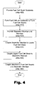
- FIG. 4 is a flowchart illustrating the fabrication of a fuel cell stack assembly according to one exemplary embodiment.
- FIG. 5 illustrates a partial cross-sectional view of a fuel cell stack assembly with a gradient pressure fuel needle according to one exemplary embodiment.
- FIG. 6 illustrates a partial cross section of a fuel cell stack assembly according to exemplary embodiment.
- FIG. 7 illustrates an exploded view of a fuel cell stack assembly according to one alternative embodiment.
- the present specification describes a fuel cell assembly that includes a plurality of opposing fuel cell stacks.
- Each of the fuel cell stacks has a plurality of fuel cells in which each fuel cell has an anode, a cathode, and an electrolyte.
- the fuel cell assembly further includes a spacing member disposed between the fuel cell stacks thereby defining a fluidic cavity, and a manifold coupled to the fluidic cavity.
- an exemplary fuel cell stack assembly generally includes an upper integrated planar array fuel cell stack ( 105 ), a lower integrated planar array fuel cell stack ( 110 ), a fuel manifold ( 115 ), a spacing member ( 120 ), a fuel needle ( 125 ), a top external electrical interconnection ( 130 ), a bottom external electrical interconnection ( 135 ) and an end electrical interconnection ( 140 ) between the two stacks ( 105 , 110 ).
- the upper fuel cell stack ( 105 ) and the lower fuel cell stack ( 110 ) each include a plurality of individual fuel cells ( 145 ) formed on the fuel cell stack ( 105 , 110 ) porous substrate.
- the spacing member ( 120 ) maintains the stacks at a pre-determined distance from each other and a glass or ceramic adhesive seals the fuel cell stacks ( 105 , 110 ). Accordingly, the spacing member ( 120 ) and the fuel cell stacks ( 105 , 110 ) form a sealed fluidic cavity ( 150 ).
- the fuel manifold ( 115 ) may be fluidly coupled to the fluidic cavity ( 150 ) by the fuel needle ( 125 ).
- the fuel cell stacks ( 105 , 110 ) shown in FIG. 1 are fabricated on top of a porous ceramic substrate and may be formed of integrated planar arrays of individual fuel cells. Accordingly, the fuel cells may be formed on a plate shaped ceramic substrate in order to form planar arrays of individual fuel cells.
- the spacing member ( 120 ) separating the fuel cell stacks ( 105 , 110 ) is formed of a material having a coefficient of thermal expansion similar to that of the ceramic material used to form the fuel cell stacks ( 105 , 110 ).
- the fuel cell stacks ( 105 , 110 ) may only be coupled to the fuel manifold ( 115 ) at one end of the fuel cell stack assembly ( 100 ).
- the result may be a fuel manifold coupled to a first end of the assembly, whereby the fuel cell stacks cantilever from the manifold.
- Such a configuration minimizes the seal length between dissimilar materials such as the metallic materials of the manifold ( 115 ) and the ceramic materials of the fuel cell stacks ( 105 , 110 ). This minimization of the seal length reduces the stresses induced into the present system due to different coefficients of thermal expansion during the temperature cycling that accompanies fuel cell operation.
- the single connection point allows the fuel cell stack assembly ( 110 ) to expand or contract unconstrained as a cantilever structure.
- the fuel cell stacks ( 105 , 110 ) may include a higher number of individual fuel cells ( 145 ; FIG. 1 ) due to the reduced risk of cracking the fuel cells or the seals during thermal expansion.
- This ability to incorporate a higher number of fuel cells leads to higher volumetric power density, higher stack voltages, and correspondingly lower stack electrical parasitic losses.
- the fuel manifold ( 115 ) illustrated in FIG. 1 is configured to introduce fuel into fluidic cavity ( 150 ) by way of a fuel needle ( 125 ). Fuel entering through the manifold ( 115 ) is distributed through the needle ( 125 ) along the length of the fluidic cavity ( 150 ).
- One embodiment of the needle ( 125 ) may be a hollow tube or pipe with an exhaust hole at its end for releasing fuel from the manifold ( 125 ) into the fluidic cavity ( 150 ). A majority of the released fuel is then consumed from the fluidic cavity ( 150 ) by the fuel cell stacks ( 105 , 110 ).
- a single manifold ( 115 ) having a single fuel needle ( 125 ) may adequately supply fuel to two or more fuel cell stacks ( 105 , 110 ) and dispose of excess fuel and reactants.
- the fuel is contained within the cavity ( 150 ), thereby reducing the possibility of creating a volatile fuel mixture outside of the cavity ( 150 ).
- the internal electrical interconnects ( 160 ) shown in FIG. 1 facilitate efficient current withdrawal from the fuel cell stack assembly ( 100 ).
- Each of the individual fuel cells ( 145 ) are electrically coupled with adjacent fuel cells in the fuel cell stacks ( 105 , 110 ) by way of the internal electrical interconnects ( 160 ).
- the internal electrical interconnects ( 160 ) are, in turn, coupled to the external interconnections ( 130 , 135 ) and the end electrical interconnection ( 140 ) which electrically connects multiple stacks in series.
- the external interconnections may then, in turn, be coupled to an external current consuming device (not shown) for which the fuel cell assembly is providing power.
- the internal electrical interconnects ( 160 ) illustrated in FIG. 1 may be formed using conductive metal, ceramic, or cermet interconnection strips that are imbedded in the thin film deposition of the anode/electrolyte/cathode system.
- the use of internal electrical interconnects reduces the number of external electrical interconnections associated with the fuel cell.
- Such a configuration provides for a higher net stack operating voltage and correspondingly lower stack current, which in turn results in lower electrical parasitic losses for the stack, higher efficiencies, and more efficient manufacturing.
- the conductive metal, ceramic, or cermet-interconnected strips may be thin, thereby reducing the parasitic losses between the anode and the cathode, producing higher overall efficiencies.
- FIG. 2 illustrates an assembled view of the fuel cell stack assembly ( 100 ).
- the fuel cell stacks ( 105 , 110 ) are sealed with the spacing member ( 120 ) there between.
- the fuel manifold ( 115 ) extends through an opening in the spacing member ( 120 ) to provide fuel to the interior fluidic cavity between the fuel cell stacks ( 105 , 110 ).
- electrical current flows through the electrical interconnections ( 130 , 135 , 140 ) due to the reaction described above.
- the present fuel cell stack assembly has a compact design in which a plurality of fuel cell stacks ( 105 , 110 ) are assembled so as to share a fuel manifold ( 115 ) or other fluidic manifold. As discussed below, such a configuration may provide for increased volumetric power density.
- FIG. 3 illustrates partial cross sectional views of two adjacent fuel cell stack assemblies ( 100 ).
- a fuel cell needle ( 125 ) conveys fuel from the fuel manifold ( 115 ; FIG. 1 ) to the fluidic cavity ( 150 ) where it is used by the multiple fuel cells ( 145 ).
- Each fuel cell stack ( 105 , 110 ) includes multiple individual fuel cells ( 145 ) formed on a porous ceramic fuel cell stack substrate ( 300 ).
- Each individual fuel cell ( 145 ) includes an anode ( 310 ), an electrolyte ( 320 ), and a cathode ( 330 ).
- the electrolyte ( 320 ), located between the anode ( 310 ) and the cathode ( 330 ) conducts oxygen ions from air on the cathode side of the fuel cell stack ( 105 , 110 ) to the anode side where those ions react with the fuel from the fluidic cavity ( 150 ).
- each fuel cell stack assembly ( 100 ) may be connected to, and provide power for, an electronic device.
- each assembly includes two fuel cell stacks ( 105 , 110 ) for a total, in the configuration of FIG. 3 , of four fuel cell stacks.
- any number of fuel cell stacks may be used according to the present system and method.
- FIG. 3 illustrates an external oxidant space ( 340 ) formed between adjacent fuel cell assembly stacks ( 100 ).
- a single oxidant stream may supply an oxidant to two fuel cell stacks ( 105 , 110 ).
- This configuration allows the fuel cell stack assemblies ( 100 ) to be closely grouped. This close grouping further facilitates high volumetric power density and allows several fuel cell stack assemblies ( 100 ) to be grouped together to meet the power needs of a particular system.
- FIG. 4 is a flowchart illustrating a method of fabricating the fuel cell stack assembly described above.
- the fabrication process begins by providing a fuel cell stack substrate (step 400 ).
- the fuel cell stack substrate provided may be, according to one exemplary embodiment, a porous ceramic substrate shaped into a flat porous plate for ease of manufacturing.
- each fuel cell includes the formation of an anode, an electrolyte, a cathode, and electrical interconnects. Accordingly, a plurality of individual fuel cells may be formed on a single substrate plate.
- the anode, cathode, and electrical interconnects may be formed by any suitable process including, but in no way limited to, screen printing, spin-on deposition, colloidal spray deposition, doctor blade methods, etc.
- the electrolyte may be formed by any suitable process, including, by way of example, sputter deposition.
- the cathode may be any material capable of catalytically reducing gaseous oxygen, thereby creating oxygen ions including, but in no way limited to, a mixed conducting perovskite such as lanthanum manganite (LaMnO 3 ).
- the anode may be any material capable of catalytically oxidizing fuel species, such as hydrogen.
- the materials used to form the anode may include, but are in no way limited to, a ceramic/metal composite such as an electronically conducting nickel/yttria-stabilized zirconia cermet.
- the electrolyte may be any oxygen ion conducting electrolyte including, but in no way limited to, zirconia-based electrolytes such as yttria-stabilized zirconia, gadolinium-doped ceria, or a (strontium, magnesium)-doped LaGaO 3 (LSGM).
- zirconia-based electrolytes such as yttria-stabilized zirconia, gadolinium-doped ceria, or a (strontium, magnesium)-doped LaGaO 3 (LSGM).
- a fuel manifold and spacing member are provided (step 420 ).
- the spacing member may be made of a ceramic or metallic material with a coefficient of thermal expansion similar to or equal to that of the fuel cell substrate.
- the fuel manifold may be made of a metallic material or any other suitable material, preferably with the same coefficient of thermal expansion as the ceramic substrate.
- the lower fuel cell stack is then sealingly coupled to the spacing member (step 430 ), after which an upper fuel cell stack is also sealingly coupled to the spacing member (step 440 ).
- the fuel manifold is also sealingly coupled to the spacing member as well as to the upper and lower fuel cell stacks (step 450 ). As described, the fuel manifold extends through the spacing member to provide fuel to the interior of the assembly, i.e., both the upper and the lower fuel cell stacks.
- the present method enables the use of low cost, high volume ceramic manufacturing techniques to form a fuel cell stack assembly. Furthermore, a fuel manifold that is coupled to the fuel cell stacks at only one end minimizes the seal length between dissimilar materials such as the metallic materials of the manifold and the ceramic material of the fuel cell stacks and/or spacing member. This configuration reduces the stresses induced due to differences in the coefficients of thermal expansion of the two materials during the normal temperature cycling of an operating fuel cell.
- the present configuration allows of the fuel cell stack assembly to expand or contract unconstrained. This freedom of expansion leads to less cracking of the brittle fuel cells or their seals thereby improving the longevity of the fuel cell stack assembly, which in turn allows for the use of a higher number of fuel cells. This ability to incorporate a higher number of fuel cells increases volumetric power density of the system.
- the fuel cell stack assemblies may be further grouped together, thereby further increasing volumetric power density.
- FIG. 5 illustrates an exemplary fuel cell stack assembly ( 100 a ) with a gradient-opening fuel needle ( 125 a ).
- the gradient-opening fuel needle ( 125 a ) has at least two differently sized exhaust holes or openings for releasing fuel into the fluidic cavity ( 150 ).
- the needle ( 125 a ) includes a plurality of openings that vary in size from a small opening ( 500 ), including an intermediate opening ( 510 ), to a larger opening ( 520 ).
- the pressure of fuel in the fuel needle ( 125 a ) decreases as the fuel approaches the end of the fuel needle ( 125 a ) furthest from the fuel manifold.
- the small opening ( 500 ) is located near the manifold at a higher-pressure portion of the fuel needle ( 125 a ), i.e., where the fuel in the needle is under a relatively high pressure.
- the larger opening is located at a lower pressure portion of the fuel needle away from the manifold where the fuel in the needle is under a relatively low pressure.
- the pressure of the fuel in the needle is high, the high pressure will tend to cause the release of a relatively large amount of fuel.
- the smaller size of the opening ( 500 ) at the high-pressure portion of the needle ( 125 a ) will limit the amount of fuel released.
- the pressure of the fuel is low, the low pressure will not tend to expel as much fuel as would be the case under a higher fuel pressure. Consequently, the larger size opening ( 520 ) is positioned at the low-pressure portion of the needle ( 125 a ) to promote the release of additional fuel, compensating for the low pressure.
- the configuration illustrated in FIG. 5 facilitates delivery of a roughly uniform amount of fuel along the length of the needle ( 125 a ) and the fuel cell stack assembly ( 100 ) by inversely relating the size of the exhaust openings to the pressure of the fuel at that portion of the fuel needle ( 125 a ).
- Uniform fuel delivery allows for more even power production among the individual fuel cells, which in turn leads to improved performance of the fuel cell system. While three openings are shown in the illustrated implementation, any number of openings with any graduation of sizes to accommodate pressure changes may be defined in the fuel needle ( 125 a ).
- FIG. 6 illustrates yet another fuel cell stack assembly ( 600 ).
- the fuel cell stack may include a fluidic cavity ( 150 a ) in which oxygen or another oxidant is introduced by a fluid manifold ( 115 ; FIG. 1 ).
- the components of the fuel cell stack assembly ( 600 ) shown in FIG. 6 are similar to those described above with the exception that the manifold provides an oxidant rather than a fuel. Consequently, the cathodes ( 330 ) of the individual fuel cells ( 145 ) disposed in the stacks ( 105 , 110 ) are placed in communication with the fluidic cavity ( 150 a ). In previously described embodiments, the anodes ( 310 ) of the fuel cells were placed in communication with the fluidic cavity (e.g., FIGS. 3 and 5 ).
- the oxidant is conveyed to the fluidic cavity ( 150 a ) through the fluid manifold and is distributed throughout the fluidic cavity ( 150 a ) by a fluid needle ( 125 b ), which is connected to the fluid manifold.
- the fluid needle ( 125 b ) may be designed to operate in the same way as the fuel needle ( 125 ) described above.
- FIG. 6 illustrates a configuration in which the cathodes ( 330 ) of each of the fuel cells ( 145 ) are adjacent to the fluidic cavity.
- the cathodes catalytically reduce the supplied oxidant and produce oxygen ions that are then transported to the electrolyte ( 320 ) to fuel a reaction similar to that explained above thereby producing useable electricity.
- the fluidic cavity ( 150 a ) may act as either an oxidant chamber or as a fuel chamber for a plurality of fuel cell stacks. Accordingly, the fuel cell stack assembly ( 100 b ) may be adapted to meet a variety of needs.
- FIG. 7 illustrates another fuel cell stack assembly ( 700 ) wherein flow field modification features are included in the fluidic cavity ( 150 c ) to improve the fuel distribution uniformity and utilization within the stack assembly ( 700 ). While the flow field modification features ( 710 ) could take the form of any number of different geometries, FIG. 7 illustrates a serpentine fuel flow path from the introduction points of the fuel on the needle ( 125 ) to the exhaust holes ( 155 ).
Abstract
Description
Claims (45)
Priority Applications (1)
| Application Number | Priority Date | Filing Date | Title |
|---|---|---|---|
| US10/699,395 US7160642B2 (en) | 2003-10-30 | 2003-10-30 | Fuel cell stack assembly and method of fabrication |
Applications Claiming Priority (1)
| Application Number | Priority Date | Filing Date | Title |
|---|---|---|---|
| US10/699,395 US7160642B2 (en) | 2003-10-30 | 2003-10-30 | Fuel cell stack assembly and method of fabrication |
Publications (2)
| Publication Number | Publication Date |
|---|---|
| US20050095491A1 US20050095491A1 (en) | 2005-05-05 |
| US7160642B2 true US7160642B2 (en) | 2007-01-09 |
Family
ID=34550949
Family Applications (1)
| Application Number | Title | Priority Date | Filing Date |
|---|---|---|---|
| US10/699,395 Active 2025-01-12 US7160642B2 (en) | 2003-10-30 | 2003-10-30 | Fuel cell stack assembly and method of fabrication |
Country Status (1)
| Country | Link |
|---|---|
| US (1) | US7160642B2 (en) |
Cited By (7)
| Publication number | Priority date | Publication date | Assignee | Title |
|---|---|---|---|---|
| US20060003196A1 (en) * | 2004-07-01 | 2006-01-05 | Ryuji Kohno | Fuel cell and electronic device equipped with the same |
| US20060166053A1 (en) * | 2001-11-21 | 2006-07-27 | Badding Michael E | Solid oxide fuel cell assembly with replaceable stack and packet modules |
| US20070117005A1 (en) * | 2005-11-21 | 2007-05-24 | Relion, Inc. | Proton exchange membrane fuel cell and method of forming a fuel cell |
| US20090169941A1 (en) * | 2007-10-25 | 2009-07-02 | Relion, Inc. | Direct liquid fuel cell |
| US8026020B2 (en) | 2007-05-08 | 2011-09-27 | Relion, Inc. | Proton exchange membrane fuel cell stack and fuel cell stack module |
| US9293778B2 (en) | 2007-06-11 | 2016-03-22 | Emergent Power Inc. | Proton exchange membrane fuel cell |
| US10396332B2 (en) | 2006-11-10 | 2019-08-27 | Hydrogenics Corporation | Bus bar assembly for an electrochemical cell stack |
Families Citing this family (5)
| Publication number | Priority date | Publication date | Assignee | Title |
|---|---|---|---|---|
| CN101292374B (en) | 2005-08-17 | 2011-03-09 | Utc电力公司 | Solid-oxide fuel cell stack for portable power generation |
| WO2007051010A2 (en) * | 2005-10-28 | 2007-05-03 | Andrei Leonida | Fuel cell system suitable for complex fuels and a method of operation of the same |
| US20070172713A1 (en) * | 2006-01-23 | 2007-07-26 | Ketcham Thomas D | Stress reducing bus bar for an electrolyte sheet and a solid oxide fuel cell utilizing such |
| KR20190003665A (en) * | 2016-05-02 | 2019-01-09 | 콘비온 오와이 | Stack Structure and Method of High Temperature Fuel Cell Stack |
| US10690289B2 (en) * | 2017-11-02 | 2020-06-23 | Lincoln Global, Inc. | Modular gas control attachment assembly for cylinders |
Citations (5)
| Publication number | Priority date | Publication date | Assignee | Title |
|---|---|---|---|---|
| US4910100A (en) * | 1989-07-21 | 1990-03-20 | Fuji Electric Co., Ltd. | Solid electrolyte fuel cell |
| US5175063A (en) * | 1989-09-18 | 1992-12-29 | Ngk Insulators, Ltd. | Fuel cell generator |
| US6200698B1 (en) | 1999-08-11 | 2001-03-13 | Plug Power Inc. | End plate assembly having a two-phase fluid-filled bladder and method for compressing a fuel cell stack |
| US6465119B1 (en) | 2000-07-18 | 2002-10-15 | Motorola, Inc. | Fuel cell array apparatus and method of fabrication |
| US6479178B2 (en) | 1999-11-16 | 2002-11-12 | Northwestern University | Direct hydrocarbon fuel cells |
-
2003
- 2003-10-30 US US10/699,395 patent/US7160642B2/en active Active
Patent Citations (5)
| Publication number | Priority date | Publication date | Assignee | Title |
|---|---|---|---|---|
| US4910100A (en) * | 1989-07-21 | 1990-03-20 | Fuji Electric Co., Ltd. | Solid electrolyte fuel cell |
| US5175063A (en) * | 1989-09-18 | 1992-12-29 | Ngk Insulators, Ltd. | Fuel cell generator |
| US6200698B1 (en) | 1999-08-11 | 2001-03-13 | Plug Power Inc. | End plate assembly having a two-phase fluid-filled bladder and method for compressing a fuel cell stack |
| US6479178B2 (en) | 1999-11-16 | 2002-11-12 | Northwestern University | Direct hydrocarbon fuel cells |
| US6465119B1 (en) | 2000-07-18 | 2002-10-15 | Motorola, Inc. | Fuel cell array apparatus and method of fabrication |
Cited By (11)
| Publication number | Priority date | Publication date | Assignee | Title |
|---|---|---|---|---|
| US20060166053A1 (en) * | 2001-11-21 | 2006-07-27 | Badding Michael E | Solid oxide fuel cell assembly with replaceable stack and packet modules |
| US20060003196A1 (en) * | 2004-07-01 | 2006-01-05 | Ryuji Kohno | Fuel cell and electronic device equipped with the same |
| US20070117005A1 (en) * | 2005-11-21 | 2007-05-24 | Relion, Inc. | Proton exchange membrane fuel cell and method of forming a fuel cell |
| US7833645B2 (en) | 2005-11-21 | 2010-11-16 | Relion, Inc. | Proton exchange membrane fuel cell and method of forming a fuel cell |
| US10396332B2 (en) | 2006-11-10 | 2019-08-27 | Hydrogenics Corporation | Bus bar assembly for an electrochemical cell stack |
| US8026020B2 (en) | 2007-05-08 | 2011-09-27 | Relion, Inc. | Proton exchange membrane fuel cell stack and fuel cell stack module |
| US8192889B2 (en) | 2007-05-08 | 2012-06-05 | Relion, Inc. | Proton exchange membrane fuel cell stack and fuel cell stack module |
| US8597846B2 (en) | 2007-05-08 | 2013-12-03 | Relion, Inc. | Proton exchange membrane fuel cell stack and fuel cell stack module |
| US9293778B2 (en) | 2007-06-11 | 2016-03-22 | Emergent Power Inc. | Proton exchange membrane fuel cell |
| US20090169941A1 (en) * | 2007-10-25 | 2009-07-02 | Relion, Inc. | Direct liquid fuel cell |
| US8003274B2 (en) | 2007-10-25 | 2011-08-23 | Relion, Inc. | Direct liquid fuel cell |
Also Published As
| Publication number | Publication date |
|---|---|
| US20050095491A1 (en) | 2005-05-05 |
Similar Documents
| Publication | Publication Date | Title |
|---|---|---|
| US8268502B2 (en) | Fuel cell stack components | |
| TW527746B (en) | Direct methanol fuel cell including integrated flow field and method of fabrication | |
| US6972161B2 (en) | Fuel cell assembly and method of making the same | |
| US7329471B2 (en) | Methods and apparatus for assembling solid oxide fuel cells | |
| US6489050B1 (en) | Apparatus and method for cooling high-temperature fuel cell stacks | |
| EP1300903B1 (en) | A miniaturized solid-oxide fuel cell | |
| US7160642B2 (en) | Fuel cell stack assembly and method of fabrication | |
| US20070048589A1 (en) | Integrated micro fuel cell apparatus | |
| US20180123143A1 (en) | Electrochemical reaction unit and fuel cell stack | |
| US20040247980A1 (en) | Structurally yieldable fuel cell seal | |
| EP1685621B1 (en) | Multi-cell fuel layer and system | |
| WO2003081703A2 (en) | Fuel cell flow field pattern | |
| JPH10189017A (en) | Gas seal structure of honeycomb structure solid electrolyte fuel cell | |
| US20040086767A1 (en) | Fuel cell assembly and reactant distribution structure and method of making the same | |
| US20040067404A1 (en) | Fuel cell assembly and reactant distribution structure and method of making the same | |
| JPH05266910A (en) | Solid electrolyte fuel cell system | |
| JPH10312818A (en) | Solid electrolyte type fuel cell | |
| US20220393219A1 (en) | Fuel plenum and fuel cell stack including same | |
| KR102548218B1 (en) | Solid oxide fuel cells and method of the same | |
| US11764389B2 (en) | Fuel cell manifold having an embedded dielectric layer and methods of making thereof | |
| JP4228895B2 (en) | Solid oxide fuel cell | |
| JPH0589895A (en) | Solid electrolyte type fuel cell |
Legal Events
| Date | Code | Title | Description |
|---|---|---|---|
| AS | Assignment |
Owner name: HEWLETT-PACKARD DEVELOPMENT COMPANY, L.P., TEXAS Free format text: ASSIGNMENT OF ASSIGNORS INTEREST;ASSIGNORS:TARVER, GARY D;KEARL, DANIEL A;GILMAN, JOHN;AND OTHERS;REEL/FRAME:014665/0152;SIGNING DATES FROM 20031015 TO 20031027 |
|
| STCF | Information on status: patent grant |
Free format text: PATENTED CASE |
|
| CC | Certificate of correction | ||
| FPAY | Fee payment |
Year of fee payment: 4 |
|
| AS | Assignment |
Owner name: EVEREADY BATTERY COMPANY, INC., MISSOURI Free format text: ASSIGNMENT OF ASSIGNORS INTEREST;ASSIGNORS:HEWLETT-PACKARD DEVELOPMENT COMPANY, L.P.;HEWLETT-PACKARD COMPANY;REEL/FRAME:026463/0542 Effective date: 20101029 |
|
| AS | Assignment |
Owner name: INTELLIGENT ENERGY LIMITED, UNITED KINGDOM Free format text: ASSIGNMENT OF ASSIGNORS INTEREST;ASSIGNOR:EVEREADY BATTERY COMPANY, INC.;REEL/FRAME:032124/0514 Effective date: 20131219 |
|
| FPAY | Fee payment |
Year of fee payment: 8 |
|
| MAFP | Maintenance fee payment |
Free format text: PAYMENT OF MAINTENANCE FEE, 12TH YEAR, LARGE ENTITY (ORIGINAL EVENT CODE: M1553) Year of fee payment: 12 |