US7159853B2 - Welded barrier system - Google Patents
Welded barrier system Download PDFInfo
- Publication number
- US7159853B2 US7159853B2 US10/926,912 US92691204A US7159853B2 US 7159853 B2 US7159853 B2 US 7159853B2 US 92691204 A US92691204 A US 92691204A US 7159853 B2 US7159853 B2 US 7159853B2
- Authority
- US
- United States
- Prior art keywords
- barrier
- rail
- upright member
- ridge
- weld
- Prior art date
- Legal status (The legal status is an assumption and is not a legal conclusion. Google has not performed a legal analysis and makes no representation as to the accuracy of the status listed.)
- Expired - Lifetime
Links
Images


Classifications
-
- E—FIXED CONSTRUCTIONS
- E04—BUILDING
- E04H—BUILDINGS OR LIKE STRUCTURES FOR PARTICULAR PURPOSES; SWIMMING OR SPLASH BATHS OR POOLS; MASTS; FENCING; TENTS OR CANOPIES, IN GENERAL
- E04H17/00—Fencing, e.g. fences, enclosures, corrals
- E04H17/14—Fences constructed of rigid elements, e.g. with additional wire fillings or with posts
- E04H17/1413—Post-and-rail fences, e.g. without vertical cross-members
- E04H17/1417—Post-and-rail fences, e.g. without vertical cross-members with vertical cross-members
- E04H17/1426—Picket fences
- E04H17/1439—Picket fences with separate pickets going through the horizontal members
-
- B—PERFORMING OPERATIONS; TRANSPORTING
- B21—MECHANICAL METAL-WORKING WITHOUT ESSENTIALLY REMOVING MATERIAL; PUNCHING METAL
- B21F—WORKING OR PROCESSING OF METAL WIRE
- B21F27/00—Making wire network, i.e. wire nets
- B21F27/08—Making wire network, i.e. wire nets with additional connecting elements or material at crossings
- B21F27/10—Making wire network, i.e. wire nets with additional connecting elements or material at crossings with soldered or welded crossings
-
- E—FIXED CONSTRUCTIONS
- E04—BUILDING
- E04H—BUILDINGS OR LIKE STRUCTURES FOR PARTICULAR PURPOSES; SWIMMING OR SPLASH BATHS OR POOLS; MASTS; FENCING; TENTS OR CANOPIES, IN GENERAL
- E04H17/00—Fencing, e.g. fences, enclosures, corrals
- E04H17/14—Fences constructed of rigid elements, e.g. with additional wire fillings or with posts
- E04H17/1413—Post-and-rail fences, e.g. without vertical cross-members
- E04H17/1447—Details of connections between rails and posts
- E04H17/1448—Adjustable, angled or hinged connections
Definitions
- the present invention relates generally to barriers to pedestrians or vehicles, and more particularly to fences and fence components assembled by a resistance projection welding process.
- the present invention comprises a barrier formed from at least one elongate rail and at least one vertical upright member.
- the rail is characterized by a flat web and a pair of opposed side walls which extend from the web to define a rail channel.
- a weld-forming region which projects within the rail channel is formed in at least one of the side walls.
- the upright member is partially situated within the rail channel and is secured to the rail by a weld. The weld is formed within the rail channel at the weld-forming region, between the side-wall and the upright member.
- the invention further comprises a method of assembling a barrier from at least one conductive upright member and at least one elongate conductive rail.
- the rail is characterized by a flat web and a pair of opposed side walls which extend from the web to define a rail channel.
- a weld-forming region which projects within the rail channel is formed in at least one of the side walls.
- the upright member is transversely positioned within the rail channel such that it contacts the weld-forming region.
- the upright member is contacted with an electrode having a first polarity, while the rail is contacted with an electrode having a second polarity opposed to the first polarity.
- a welding current is transmitted between the rail-contacting electrode and the upright member-contacting electrode to cause the weld-forming region to form a weld within the rail channel. This weld joins the upright member to the rail.
- FIG. 1 is a front elevational view of a section of fence embodying the present invention, showing a panel supported between a pair of adjacent posts. The supporting terrain is shown in cross section.
- FIG. 2 is an enlarged and detailed front elevational view of one of the rails forming the panel shown in FIG. 1 , prior to its assembly into the panel.
- FIG. 3 is a cross-sectional view of the rail shown in FIG. 3 , taken along line 3 — 3 .
- FIG. 4 is a top plan view of the rail shown in FIGS. 2 and 3 , taken along line 4 — 4 .
- FIG. 5 is a cross-sectional view of the rail and upright member of the fence shown in FIG. 2 in a partially assembled state, prior to welding.
- FIG. 6 is a cross-sectional view of the rail and upright member shown in FIG. 5 , in assembled form after welding has taken place.
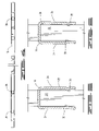
- FIG. 7 is a front elevational view of a section of another type of fence embodying the present invention, showing a panel supported between a pair of adjacent posts. The supporting terrain is shown in cross section.
- FIG. 8 is a top plan view of the upper rail of the panel shown in FIG. 7 , taken along line 8 — 8 .
- FIG. 9 is cross-sectional view of the assembled rail and upright member of the fence shown in FIGS. 7 and 8 , after welding has taken place, taken along line 9 — 9 .
- FIG. 10 is an enlarged and detailed front elevational view of another embodiment of the rail of the present invention, prior to its assembly into a fence or panel.
- the present invention comprises a barrier, such as a fence, balustrade, or gate, formed from at least one, and preferably a plurality of, elongate rails, and at least one, and preferably a plurality, of upright members.
- FIG. 1 shows the barrier of the present invention as embodied in a fence, generally designated by reference numeral 10 .
- the fence 10 preferably comprises a plurality of spaced vertical posts 12 , preferably identical in construction, each of which is securely anchored at its base into a substrate 14 , such as the ground, or an underground mass of concrete.
- the posts 12 are situated along the boundary of the area to be enclosed by the fence 10 , with a post spacing which is adequate to impart strength to the fence 10 and to securely anchor other fence components. In the FIG. 1 embodiment, a post separation distance of 8 feet would be typical.
- Each post 12 is preferably formed from a strong and durable material, such as sheet steel or aluminum.
- the sheet used to form the post 12 is characterized by a thickness of 0.059 inches.
- the sheet is preferably subjected to a pre-galvanizing treatment.
- the pre-galvanized sheet is then subjected to a cold rolling process to form the rail into a tubular configuration, preferably having a rectangular cross-section.
- the post may be formed with a circular cross-section.
- a polyester powder coating is preferably provided in order to further enhance corrosion resistance of the post 12 .
- the fence 10 may be formed from a plurality of panels 16 , each of which is supported by, and extends between, an adjacent pair of posts 12 .
- Each panel 16 is formed from at least one rail 18 , and at least one upright member 20 . More preferably, each panel 16 is formed from a plurality of spaced and parallel rails 18 , and a plurality of spaced and parallel upright members 20 , such as the pickets shown in FIG. 1 .
- the upright members 20 forming each panel 16 preferably extend in substantially perpendicular relationship to the rails 18 forming that panel.
- each panel 16 While any number of rails may be provided for each panel 16 , either two rails, as shown in FIG. 1 , or three rails, as shown in FIG. 7 , are preferred.
- the number of upright members 20 provided for each panel 16 should be sufficiently great to assure that the separation distance between adjacent upright members 20 , or between a post 12 and an adjacent upright member 20 , will not permit an intruder to travel between them. For example, in a panel to be installed between posts which are separated by an 8-foot distance, twenty-one upright members may be provided, with a uniform separation distance of 4.334 inches.
- each rail 18 is characterized by an elongate flat web 22 and a pair of opposed side walls 24 and 26 which extend from the web 22 .
- the web 22 and side walls 24 and 26 collectively define a U-shaped rail channel 28 .
- the length of each rail 18 should be sufficient to fully span the distance between the adjacent of pair of posts 12 which will support that rail, or support the panel 16 into which the rail will be incorporated.
- Each rail 18 is preferably formed from a strong, durable and conductive material, such as a sheet steel or aluminum.
- the sheet is characterized by a thickness of 0.075 inches.
- the sheet is preferably subjected to a pre-galvanizing treatment.
- the pre-galvanized sheet is then subjected to a cold rolling process to produce the cross-sectional shape shown in FIG. 3 .
- At least one, and preferably both, of the side walls 24 and 26 include a weld-forming region 30 which projects within the rail channel 28 .
- a weld-forming region has been formed in each side wall.
- Each weld-forming region 30 may comprise a longitudinal ridge which extends along at least a portion of the length of its respective side wall, preferably in substantially parallel relationship to the longitudinal axis of the rail 18 . More preferably, each ridge extends continuously along substantially the entire length of its associated side wall.
- weld-forming regions comprise ridges
- they are preferably formed during the cold rolling process.
- One or more continuous longitudinal scores 32 are preferably formed in the surface of the sheet which will not define the rail channel 28 . These scores 32 cause ridges to protrude from the opposite surface of the sheet. When that surface is formed into the rail channel 28 by the cold rolling process, each of the protrusions will define an elongate ridge which projects within the rail channel 28 and comprises a weld-forming region 30 , as shown in FIG. 2 .
- each weld-forming region 30 should be selected so that the region can effectively concentrate a welding current flow.
- a preferred height for the weld-forming region 30 is 0.035 inches.
- a preferred width for the weld-forming region 30 is 0.143 inches.
- a pointed and or angular profile for the weld-forming region 30 is preferred.
- Opposed and aligned fastener openings 34 are formed at each of the side walls 24 and 26 , preferably at each of the opposite ends of the rail 18 .
- a plurality of longitudinally spaced top openings 36 are preferably also formed in the web 22 of at least one of the rails 18 , more preferably in all of the rails 18 , with the possible exception of the uppermost rail 18 .
- top openings 36 are formed in all of the rails 18 .
- the fastener openings 34 and top openings 36 are formed by punching from the sheet used to form the rail 18 , before that sheet undergoes the cold rolling process used to form the rail 18 .
- the top openings should be characterized by identical size and shape, which preferably is rectangular.
- Each upright member 20 is preferably formed from a strong, durable and conductive material, such as sheet steel or aluminum.
- the sheet used to form the upright member 20 is characterized by a thickness of 0.040 inches.
- this sheet is preferably subjected to a pre-galvanizing treatment.
- the pre-galvanized sheet is then subjected to a cold rolling process to form the upright member into a tubular configuration, preferably having a rectangular cross-section.
- each of the upright members 20 is preferably sized to be closely but clearingly received within the rail channel 28 of each rail 18 , and to be closely but clearingly received through any top openings 36 formed in any of the rails 18 to which it will be attached.
- the vertical height of each upright member 20 is preferably approximately equal to the above-ground vertical height of the posts 12 .
- each upright member 20 is characterized by a substantially straight-line longitudinal axis.
- each upright member may be characterized by a longitudinal axis having a lower portion which is straight, in the area of the point or points of attachment to the rail 18 , and an upper portion which bends or curves away from the straight lower portion.
- a plurality of upright members 20 are provided, they are preferably identical.
- an upright member 20 is secured to a rail 18 by transversely positioning the upright member 20 within the rail channel 28 , such that the upright member 20 is partially situated within the rail channel 28 in the desired position relative to the rail 18 . In this position, the upright member 20 will ordinarily extend longitudinally in substantially perpendicular relationship to the rail 18 .
- the upright member 20 While positioned within the rail channel 28 as described above, the upright member 20 should contact at least one, and preferably an opposed pair, of the weld-forming regions 30 formed in the rail 18 .
- the rail 18 to which upright member 20 is to be secured includes top openings 36 , as in FIG. 5 , the upright member 20 should extended through a corresponding top opening 36 so as to fully traverse the rail channel 28 .
- the upright member 20 is contacted with a first electrode (not shown) having a first polarity, and the rail 18 is contacted with a second electrode (not shown) having a second polarity opposed to the first polarity.
- the point of contact for each electrode is near the weld-forming regions 30 .
- a welding current is then transmitted between the rail-contacting electrode and the upright member-contacting electrode.
- the welding current is of sufficient of magnitude, and applied for sufficient time, so that the electrical resistance of the rail 18 causes each of the weld-forming regions 30 contacting the upright member 20 to heat up and at least partially melt.
- Current flow is then terminated, and the melted portions of the weld-forming regions cool to form welds 38 , as shown in FIG. 6 .
- the rail 18 is preferably compressed during the periods of current flow and cooling, such that each of the weld-forming regions 30 is pressed against upright member 20 .
- the compressive force is preferably applied by the electrodes.
- Each of the resulting welds 38 is situated within the rail channel 28 and joins the upright member 20 to the rail 18 , resulting in a upright member-rail assembly.
- an opposed pair of welds 38 is formed within the rail channel 28 .
- the source of the welding current is preferably a direct current inverter power supply, such as the model IS-471B, manufactured by Unitek Myachi Corporation of Monrovia, Calif.
- a direct current inverter power supply converts commercial alternating current into a high frequency direct current which is fed via a transformer to electrodes in a welding head.
- a weld current of 22,000 amperes and a frequency of 1000 Hertz is used to form the welds.
- Preferably 2 cycles of such a current is used to form each weld.
- Additional rails 18 and upright members 20 may be attached to the welded upright member-rail assembly by repeating the steps described above, until a fence panel 16 has been formed.
- an upright member 20 will be transversely positioned within the rail channel 28 of the rail 18 to which it is to be secured, so that it contacts at least one, and preferably both, of the weld-forming regions 30 .
- the upright member 20 is contacted with an electrode having a first polarity
- the rail 18 is contacted with an electrode having a second polarity opposed to the first polarity.
- each panel 16 is assembled as described, it is preferably provided with a polyester powder coating in order to enhance its resistance to corrosion.
- the welding steps required to assembled a panel 16 from rails 18 and upright members 20 may be performed in succession, or some or all of these steps may be performed simultaneously, preferably using a separate pair of electrodes to form each weld.
- the panel 16 shown in FIG. 1 seven adjacent upright members 20 may be welded simultaneously to both the upper and lower rails 18 .
- the assembly process would entail three sequential welding steps, commencing from one end of the panel and proceeding to the other, with fourteen simultaneous welds being formed in each such step.
- the welding steps required to form a panel 16 may advantageously be performed with automated equipment, such as a press-type welding machine.
- a welding machine may comprise one or more welding heads, each of which contains first and second electrodes which can respectively contact an upright member 20 and an associated rail 18 . While current flows between the first and second electrodes, the welding machine simultaneously pressurizes the joint between the upright member 20 and rail 18 . When the head is retracted, the partially assembled panel may be repositioned, so that another weld or group of welds may be formed.
- the welds used to assemble each panel 16 are formed internally within the rail channels 28 .
- the exterior surfaces of the panel 16 of the present invention accordingly do not display any of the visible blemishes and marks which are characteristic of other assembly methods, such as those involving other types of welding.
- the longitudinal ridge formed in each rail 18 also enhances the strength of the rail 18 .
- each panel 16 is supported from an adjacent pair of posts 12 by a plurality of brackets 40 , each of which is mounted on a post 12 .
- Each bracket 40 includes fastener openings (not shown) which may be aligned with corresponding fastener openings 34 formed in each end of each rail 18 .
- a fastener 42 is inserted through aligned openings and secured in place by a holder (not shown), such as a nut or collar.
- a holder such as a nut or collar.
- more than one bracket 40 may be installed at same vertical position on the post 12 .
- each rail 18 of the assembled fence 10 is supported at opposite ends by brackets 40 mounted on an adjacent pair of posts 12 .
- Each rail 18 is disposed such that the channels 28 open downwardly and the side walls 24 and 26 extend substantially vertically.
- the incline of the rails 18 with respect to horizontal should substantially equal the incline of the terrain 44 on which pair of posts 12 supporting that panel are installed.
- the rails 18 will be disposed substantially horizontally.
- each of the upright members 20 projects above the highest rail and below the lowest rail of the panel.
- the upper end of each upright member 20 may be formed into a pointed or sharpened configuration which will deter and hinder climbing, such as a spear or spike. Alternately, upright members 20 having round or flat tops may be used.
- the lower end of each upright member 20 is preferably situated no more than a small distance above the terrain 44 supporting the fence 10 , in order to prevent an intruder from traversing the gap between the base of the upright member 20 and the terrain 44 .
- FIG. 7 shows another embodiment of the barrier of the present invention, comprising a fence 50 formed from a plurality of panels 52 , each of which is supported by, and extends between, an adjacent pair of posts 54 .
- Each of the panels 52 is formed from three rails: an upper rail 54 , and two lower rails 56 and 58 .
- the lower rails 56 and 58 are identical to the rail 18 described with reference to embodiment of FIGS. 1–6 .
- each panel 52 is identical to the lower rails 56 and 58 , except that no openings are formed in its web 60 .
- the upright members 62 forming each panel 52 accordingly cannot extend through the web 60 of the upper rail 56 , and accordingly do not project above the upper rail, as illustrated in FIG. 7 . Instead each upright member 62 comprising the panel 52 terminates at its upper end within the rail channel 64 of the upper rail 56 , preferably in abutment with the web 60 .
- the fence 50 , panels 52 , and their respective components and methods of assembly are identical to those described with reference to the embodiment of FIG. 1-6 .
- FIG. 10 shows another embodiment of the rail of the present invention, generally designated by reference numeral 70 .
- the rail 70 is identical to the rail 18 described with reference to FIGS. 1 through 6 , except that the weld-forming region comprises at least one, and preferably a plurality of longitudinally spaced nipple-shaped projections, rather than a continuous ridge.
- the cross-sectional profile of each of these nipple-shaped projections which are preferably axially symmetrical, is the same as the cross-sectional profile of the weld-forming region 30 shown in FIG. 3 .
- the preferred width and height of the projection are likewise the same as described with reference to FIG. 3 .
- a weld-forming region comprising a plurality of longitudinally spaced nipple-shaped projections is formed in each of the side walls 72 of the rail 70 .
- Projections formed in the respective side walls may be arranged in direct face-to-face to opposition, or the projections may be arranged in alternation, such that a projection on one side wall is disposed opposite a gap between adjacent projections in the other side wall.
- the rail 70 is preferably formed from the same materials, and by substantially the same cold rolling process as described with reference to the rail 18 .
- the only difference in the manufacturing process for the rail 70 is that no scores are impressed on the sheet during the cold rolling process, so that no ridges are formed within the rail channel. Instead, a plurality of longitudinally spaced dimple-shaped indentations 74 are formed on the sheet used to form the rail 70 , preferably before commencement of the cold rolling process. If the rail 70 includes more than one weld-forming region, then a set of longitudinally spaced indentations will be formed for each such region to be formed.
- the dimple-shaped indentations should be formed in the surface of the sheet which will not define the rail channel, preferably by a press punch. These dimple-shaped indentations 74 cause nipple-shaped projection to protrude from the opposite surface of the sheet. When that surface is formed into the rail channel by the cold rolling process, each of these protrusions will define a nipple-shaped projection which projects within the rail channel and comprises a weld-forming region.
- the resulting rail 70 may be used, with or without top openings in the web, in any of the barriers of the present invention, such as panels 16 and 52 , and fences 10 and 50 .
- the present invention has been described with reference to fences, and methods for their assembly, it should be understood that the invention is equally adaptable to any barrier formed from one or more rails and one or more upright member.
- Other types of barriers which can be formed in accordance with the present invention include balustrades, hand rail systems, guard rail systems, and gates.
- the barrier of the present incorporates a hand rail
- the upper rail of the preferably includes no top openings, so that the upper rail presents a smooth and regular surface suitable for gripping by a hand.
Landscapes
- Engineering & Computer Science (AREA)
- Architecture (AREA)
- Civil Engineering (AREA)
- Structural Engineering (AREA)
- Mechanical Engineering (AREA)
- Fencing (AREA)
- Refuge Islands, Traffic Blockers, Or Guard Fence (AREA)
- Resistance Welding (AREA)
Abstract
Description
Claims (82)
Priority Applications (1)
| Application Number | Priority Date | Filing Date | Title |
|---|---|---|---|
| US10/926,912 US7159853B2 (en) | 2002-05-07 | 2004-08-26 | Welded barrier system |
Applications Claiming Priority (2)
| Application Number | Priority Date | Filing Date | Title |
|---|---|---|---|
| US10/140,915 US6811145B2 (en) | 2002-05-07 | 2002-05-07 | Barrier formed by resistance projection welding |
| US10/926,912 US7159853B2 (en) | 2002-05-07 | 2004-08-26 | Welded barrier system |
Related Parent Applications (1)
| Application Number | Title | Priority Date | Filing Date |
|---|---|---|---|
| US10/140,915 Continuation US6811145B2 (en) | 2002-05-07 | 2002-05-07 | Barrier formed by resistance projection welding |
Publications (2)
| Publication Number | Publication Date |
|---|---|
| US20050092978A1 US20050092978A1 (en) | 2005-05-05 |
| US7159853B2 true US7159853B2 (en) | 2007-01-09 |
Family
ID=29399523
Family Applications (6)
| Application Number | Title | Priority Date | Filing Date |
|---|---|---|---|
| US10/140,915 Expired - Fee Related US6811145B2 (en) | 2002-05-07 | 2002-05-07 | Barrier formed by resistance projection welding |
| US10/666,105 Expired - Fee Related US7282659B1 (en) | 2002-05-07 | 2003-09-18 | Panel assembly apparatus |
| US10/926,858 Abandoned US20050023514A1 (en) | 2002-05-07 | 2004-08-26 | Internally welded barrier |
| US10/926,912 Expired - Lifetime US7159853B2 (en) | 2002-05-07 | 2004-08-26 | Welded barrier system |
| US10/926,857 Expired - Lifetime US7071439B2 (en) | 2002-05-07 | 2004-08-26 | Method for barrier assembly |
| US10/926,888 Abandoned US20050023515A1 (en) | 2002-05-07 | 2004-08-26 | Barrier formed by resistance projection welding |
Family Applications Before (3)
| Application Number | Title | Priority Date | Filing Date |
|---|---|---|---|
| US10/140,915 Expired - Fee Related US6811145B2 (en) | 2002-05-07 | 2002-05-07 | Barrier formed by resistance projection welding |
| US10/666,105 Expired - Fee Related US7282659B1 (en) | 2002-05-07 | 2003-09-18 | Panel assembly apparatus |
| US10/926,858 Abandoned US20050023514A1 (en) | 2002-05-07 | 2004-08-26 | Internally welded barrier |
Family Applications After (2)
| Application Number | Title | Priority Date | Filing Date |
|---|---|---|---|
| US10/926,857 Expired - Lifetime US7071439B2 (en) | 2002-05-07 | 2004-08-26 | Method for barrier assembly |
| US10/926,888 Abandoned US20050023515A1 (en) | 2002-05-07 | 2004-08-26 | Barrier formed by resistance projection welding |
Country Status (1)
| Country | Link |
|---|---|
| US (6) | US6811145B2 (en) |
Cited By (12)
| Publication number | Priority date | Publication date | Assignee | Title |
|---|---|---|---|---|
| US20050023515A1 (en) * | 2002-05-07 | 2005-02-03 | Gibbs Edward L. | Barrier formed by resistance projection welding |
| US7396002B1 (en) | 2006-05-16 | 2008-07-08 | Gibbs Edward L | Terrain-adjustable bracket |
| US7621510B2 (en) | 2004-03-15 | 2009-11-24 | Edward L. Gibbs | Terrain-adjustable barrier |
| US20100155683A1 (en) * | 2008-12-19 | 2010-06-24 | Payne John F | Rackable Fence System |
| US7762735B2 (en) | 2006-04-27 | 2010-07-27 | Cedar Mesa Design Company, Llc | Self-locking, quick-releasing, and self-releasing ball-and-socket latch system |
| US8505880B2 (en) | 2010-07-21 | 2013-08-13 | Origin Point Brands, Llc | Fence rail support system |
| US10577825B1 (en) * | 2015-07-30 | 2020-03-03 | Ameristar Perimeter Security Usa Inc. | Conductive barrier |
| USD927730S1 (en) | 2019-10-16 | 2021-08-10 | Fortress Iron, Lp | Security fence panel |
| USD927732S1 (en) | 2019-10-16 | 2021-08-10 | Fortress Iron, Lp | Security fence panel |
| USD927731S1 (en) | 2019-10-16 | 2021-08-10 | Fortress Iron, Lp | Security fence panel |
| US11499336B2 (en) | 2019-10-16 | 2022-11-15 | Fortress Iron, Lp | Security fence |
| US11761231B1 (en) | 2004-03-15 | 2023-09-19 | Ameristar Perimeter Security Usa Inc. | Rail with brackets |
Families Citing this family (29)
| Publication number | Priority date | Publication date | Assignee | Title |
|---|---|---|---|---|
| US7086642B1 (en) * | 2000-12-26 | 2006-08-08 | Xfm, Inc. | Rackabale gate for fence and method of producing such |
| US7441751B1 (en) | 2003-10-06 | 2008-10-28 | Gibbs Edward L | Cable fence system |
| USD572374S1 (en) | 2004-01-26 | 2008-07-01 | Gibbs Edward L | Cable-reinforced bollard fence |
| US7677534B2 (en) * | 2004-03-10 | 2010-03-16 | Garden Zone, Llc | Decorative fencing system |
| US8152141B2 (en) | 2004-03-10 | 2012-04-10 | Origin Point Brands, Llc | Decorative fencing system |
| US20070267616A1 (en) * | 2004-03-10 | 2007-11-22 | Duane Langenwalter | Method of manufacturing a decorative fencing system |
| US7681294B2 (en) * | 2004-06-23 | 2010-03-23 | Danny Scott Payne | Metal fence picket staking apparatus and method |
| US7188826B1 (en) | 2004-11-20 | 2007-03-13 | Gibbs Edward L | Internal clip for a rail |
| ITPS20050015A1 (en) * | 2005-06-15 | 2006-12-16 | Angelo Candiracci | SIMPLIFIED AUTOMATIC MACHINE FOR THE PRODUCTION OF PREFABRICATED BUILDING PANELS IN SANDWICH OF METALLIC NETWORKS AND EXPANDED PLASTIC MATERIAL |
| US7500371B2 (en) | 2005-11-18 | 2009-03-10 | Acco Brands Usa Llc | Locking device with passage |
| US20080179581A1 (en) * | 2007-01-29 | 2008-07-31 | Northeastern Fence & Supply Corporation | Picket fence kit |
| USD566292S1 (en) | 2007-01-30 | 2008-04-08 | Gibbs Edward L | Fence |
| US7461833B1 (en) | 2007-01-30 | 2008-12-09 | Gibbs Edward L | Picket assembly for a post |
| USD573270S1 (en) | 2007-02-09 | 2008-07-15 | Gibbs Edward L | Corner picket crown and post assembly for a fence |
| US8899555B2 (en) * | 2007-09-06 | 2014-12-02 | Fortress Iron, Lp | Adjustable picket fence |
| USD596760S1 (en) * | 2008-04-01 | 2009-07-21 | Bock John E | Fence |
| AU2010253755B2 (en) | 2009-05-29 | 2015-08-27 | Acco Brands Usa Llc | Security apparatus including attachment device |
| JP5554197B2 (en) * | 2010-09-29 | 2014-07-23 | 本田技研工業株式会社 | Spot welding method and apparatus |
| USD665510S1 (en) * | 2011-02-03 | 2012-08-14 | Lisa Esposito | Railing unit for a fence |
| US20120272477A1 (en) * | 2011-04-28 | 2012-11-01 | Larry Mirick | Hinge with weld guide |
| US8210418B1 (en) * | 2011-06-09 | 2012-07-03 | Landoll Corporation | Multi-station, gantry-based automated welding system |
| US10697199B2 (en) * | 2017-05-07 | 2020-06-30 | Shawn Hellenbrand | Stable, non-locking picket fence system |
| US11035147B2 (en) | 2018-01-08 | 2021-06-15 | Fortress Iron, Lp | Raking barrier panel |
| CN109822187A (en) * | 2019-03-06 | 2019-05-31 | 张荐 | Multiple rows of spot welding unit and preparation method thereof |
| USD948330S1 (en) | 2020-06-15 | 2022-04-12 | Origin Point Brands, Llc | Faceted conoidal connector |
| USD951082S1 (en) | 2020-06-15 | 2022-05-10 | Origin Point Bran Ds, Llc | Smooth incurvate connector |
| US12209428B2 (en) * | 2021-04-29 | 2025-01-28 | Hebei Minmetals Co., Ltd. | Fencing panel |
| US12601198B2 (en) * | 2023-11-01 | 2026-04-14 | Vantage Fence USA | Panel for a rackable barrier |
| TWI873063B (en) * | 2024-07-30 | 2025-02-11 | 廈興國際股份有限公司 | Vertical and horizontal rod fixing structure of pet guardrail |
Citations (70)
| Publication number | Priority date | Publication date | Assignee | Title |
|---|---|---|---|---|
| US313825A (en) * | 1885-03-10 | Iron fence | ||
| US895297A (en) | 1908-08-04 | Francis A Peter | Iron fence. | |
| US1630492A (en) | 1924-06-09 | 1927-05-31 | Simmons Co | Connection for tubes |
| US1782234A (en) | 1928-12-31 | 1930-11-18 | Otto U Hofmann | Method of welding and the resultant product |
| US1906296A (en) | 1930-11-29 | 1933-05-02 | Edward T Williams | Evaporator |
| US2218954A (en) | 1939-08-07 | 1940-10-22 | Cyclone Fence Company | Adjustable grade iron fence |
| US2482592A (en) | 1944-09-16 | 1949-09-20 | Diebold Inc | Metal door construction |
| US2590929A (en) | 1947-11-19 | 1952-04-01 | William W Bush | Railing |
| US2909361A (en) | 1955-01-31 | 1959-10-20 | Leighton G Dotson | Ornamental ironwork structures |
| US3033532A (en) | 1960-05-23 | 1962-05-08 | Mcfall Harry | Railing construction |
| US3083951A (en) | 1960-05-12 | 1963-04-02 | Locke Mfg Company | Interlocking ornamental railing |
| US3139504A (en) | 1960-02-23 | 1964-06-30 | Schlatter Ag | Multipoint spot welding machine |
| US3306586A (en) | 1965-07-13 | 1967-02-28 | George E Green | Adjustable railing |
| US3343811A (en) * | 1965-10-11 | 1967-09-26 | Edward J Kusel | Heavy duty adjustable railing |
| US3385567A (en) | 1965-11-05 | 1968-05-28 | Reynolds Metals Co | Railing constructions and parts therefor or the like |
| US3395489A (en) | 1966-04-19 | 1968-08-06 | Nat Mfg Co | Fence |
| US3410544A (en) | 1966-10-03 | 1968-11-12 | Btu Eng Corp | Furnace muffle |
| US3517474A (en) | 1967-06-16 | 1970-06-30 | Wendel & Cie Sa De | Flanged structural assembly |
| US3596880A (en) | 1968-12-17 | 1971-08-03 | American Metal Prod | Railing system |
| US3597568A (en) | 1967-03-23 | 1971-08-03 | Baustahlgewebe Gmbh | Reinforcing steel mats |
| US3612291A (en) | 1969-03-19 | 1971-10-12 | Paltier Corp | Cantilever rack with truss uprights |
| US3648982A (en) | 1970-07-06 | 1972-03-14 | Arnold Sabel | Railing connector |
| US3799506A (en) | 1972-04-14 | 1974-03-26 | G Schwartz | Fence |
| US4023683A (en) | 1975-03-12 | 1977-05-17 | Vargo William R | Internally reinforced load carrying member |
| US4174475A (en) | 1977-08-30 | 1979-11-13 | Charles Senn | Welding structure |
| US4188019A (en) | 1978-08-15 | 1980-02-12 | Meredith Manufacturing Co. Limited | Fencing construction |
| US4204375A (en) | 1976-09-30 | 1980-05-27 | Harter Corporation | Frame construction for a divider wall |
| US4238117A (en) | 1978-08-31 | 1980-12-09 | Don Newman | Railing and method of making the same |
| GB2093513A (en) | 1981-02-25 | 1982-09-02 | Malkmus Doernemann Carola | Sliding Gate |
| US4533121A (en) | 1980-06-06 | 1985-08-06 | Gene Basey | Variable pitch stair railing assembly |
| USD293718S (en) | 1983-11-16 | 1988-01-12 | Metal Fab Equipment, Inc. | Splice insert for balcony railing systems |
| DE3716343A1 (en) | 1987-05-15 | 1988-12-01 | Aderhold Hermann Adronit Werk | Fence grille |
| US4850214A (en) | 1980-02-11 | 1989-07-25 | Paul Opprecht | Method of fabricating a projection for resistance welding |
| US4883256A (en) | 1989-01-23 | 1989-11-28 | Hebda Thomas J | Picket fence and method of construction |
| US4917284A (en) | 1987-09-22 | 1990-04-17 | Monolite S.R.L. | Apparatus for manufacturing building panels |
| US4982933A (en) | 1988-01-28 | 1991-01-08 | Harbor Towne Fence, Inc. | Fence connector clip and assembly |
| US4995591A (en) | 1989-05-26 | 1991-02-26 | Humphrey William D | Retaining lock for chain link fence slats |
| USD324506S (en) | 1990-04-26 | 1992-03-10 | Chrysler Corporation | Dunnage bar for containing loads in shipping racks of freight transporting vehicles |
| US5136813A (en) | 1991-09-23 | 1992-08-11 | Fence Hardware Specialties, Inc. Dba Ameristar Fence Products | Cantilever-type sliding gate |
| US5192054A (en) * | 1991-01-24 | 1993-03-09 | Ivan Sharp | Prefabricated simulated wrought iron and like fencing systems and methods |
| US5272838A (en) | 1992-01-21 | 1993-12-28 | Ameristar Fence Products, Inc. | Gate conversion kit |
| US5345723A (en) | 1992-01-21 | 1994-09-13 | Ameristar Fence Products, Inc. | Gate conversion method |
| US5403985A (en) | 1992-07-22 | 1995-04-04 | Sung-Ho Ahn | Machine for manufacturing construction panels |
| US5443244A (en) | 1993-03-22 | 1995-08-22 | Gibbs; Edward L. | Rolled metal fence rail |
| US5927041A (en) | 1996-03-28 | 1999-07-27 | Hilti Aktiengesellschaft | Mounting rail |
| US6029954A (en) | 1997-03-18 | 2000-02-29 | Murdaca; Domenico | Railing assembly |
| USD424213S (en) | 1999-06-10 | 2000-05-02 | Dayton Technologies, Inc. | Deck railing extrusion |
| US6073414A (en) | 1997-06-12 | 2000-06-13 | Dale Industries, Inc. | Light gauge metal truss system |
| US6176043B1 (en) | 1999-01-14 | 2001-01-23 | Edward L. Gibbs | PVC gate framing system |
| US6254064B1 (en) | 1999-05-18 | 2001-07-03 | Edward L. Gibbs | Ornamental ring for fence |
| US6299143B1 (en) | 1999-01-26 | 2001-10-09 | Valentine & Company | Coupling spool |
| US6311957B1 (en) | 1997-06-19 | 2001-11-06 | Custom Iron, Inc. | Device and method for attaching balusters |
| USD465856S1 (en) | 2002-03-29 | 2002-11-19 | Edward L. Gibbs | Fence rail |
| USD466620S1 (en) | 2002-03-29 | 2002-12-03 | Edward L. Gibbs | Fence rail |
| USD467669S1 (en) | 2002-04-05 | 2002-12-24 | Edward L. Gibbs | Hand rail |
| USD468028S1 (en) | 2002-04-05 | 2002-12-31 | Edward L. Gibbs | Hand rail |
| US6519908B1 (en) | 2000-06-27 | 2003-02-18 | Nci Building Systems, L.P. | Structural member for use in the construction of buildings |
| US6627832B2 (en) | 2000-03-29 | 2003-09-30 | Global Steel, Llc | Modular steel concrete reinforcement system |
| US6631887B1 (en) | 2001-05-14 | 2003-10-14 | Roger Walmsley | Vertical fencing |
| US6648304B1 (en) | 2002-03-01 | 2003-11-18 | Xcel Distribution, Inc. | Modular fence |
| US20030234391A1 (en) | 2002-06-11 | 2003-12-25 | Paul Sheppard | Aluminum universal angle brackets |
| US6739583B2 (en) | 2001-10-05 | 2004-05-25 | David Allen Ryon | Metal fence rail |
| US6752385B2 (en) | 2002-02-12 | 2004-06-22 | Paul Robert Zen | Railing system |
| US6811145B2 (en) * | 2002-05-07 | 2004-11-02 | Edward L. Gibbs | Barrier formed by resistance projection welding |
| US6817155B2 (en) | 1997-10-14 | 2004-11-16 | Steel Construction Systems | Structural shape for use in frame construction |
| US6874767B1 (en) | 2002-04-05 | 2005-04-05 | Fence | |
| US6912787B1 (en) | 2002-08-28 | 2005-07-05 | Varco Pruden Technologies, Inc. | Method of forming a joist assembly and a chord used in such joist assembly |
| US6969051B1 (en) | 2002-11-22 | 2005-11-29 | Gibbs Edward L | Two-part rail with internal picket connection |
| US7086642B1 (en) | 2000-12-26 | 2006-08-08 | Xfm, Inc. | Rackabale gate for fence and method of producing such |
| US7090202B1 (en) | 2000-12-26 | 2006-08-15 | Xfm, Inc. | Fence and method of producing such |
Family Cites Families (16)
| Publication number | Priority date | Publication date | Assignee | Title |
|---|---|---|---|---|
| US2563530A (en) * | 1951-08-07 | Balustrade | ||
| US3780253A (en) | 1973-02-16 | 1973-12-18 | C Senn | Structure for and method of mesh welding |
| US4360285A (en) * | 1981-01-09 | 1982-11-23 | Magness Howard A | Rail and post connector |
| JPH0755376B2 (en) * | 1988-02-03 | 1995-06-14 | 東洋シヤッター株式会社 | How to make a hollow metal panel |
| GB2249327B (en) | 1990-11-01 | 1994-06-08 | Hadley Ind Plc | Fence pale and method of making same |
| GB9410571D0 (en) | 1994-05-26 | 1994-07-13 | Hadley Ind Plc | Fence pales |
| GB9515322D0 (en) * | 1995-07-26 | 1995-09-20 | Pgi Manufacturing Limited | A fabricated structure,especially a housing for a generator set,and a method of fabricating such a structure |
| US6151772A (en) | 1997-11-21 | 2000-11-28 | Pigott; Patrick C. | Automated machinery for fabricating a wrought-iron fence |
| US5971365A (en) | 1997-11-21 | 1999-10-26 | Pigott; Patrick C. | Fence construction |
| GB2350846B (en) | 1999-06-08 | 2003-09-17 | Hadley Ind Plc | Security fence |
| GB2363400B (en) | 2000-06-12 | 2004-11-10 | Hadley Ind Plc | Security fence |
| DE10037270B4 (en) * | 2000-07-28 | 2007-09-13 | Müller, Werner E. G., Prof. Dr. | Silicatein-mediated synthesis of amorphous silicates and siloxanes and their use |
| GB0105101D0 (en) | 2001-03-01 | 2001-04-18 | Hadley Ind Plc | Fence Pales |
| ATE382759T1 (en) | 2001-03-01 | 2008-01-15 | Hadley Ind Holdings Ltd | CROSS BEAM FOR SECURITY FENCE |
| GB0105102D0 (en) | 2001-03-01 | 2001-04-18 | Hadley Ind Plc | Rail for security fence or the like |
| USD468620S1 (en) * | 2002-07-09 | 2003-01-14 | Cheng-Yu Lee | Automobile door lock knob |
-
2002
- 2002-05-07 US US10/140,915 patent/US6811145B2/en not_active Expired - Fee Related
-
2003
- 2003-09-18 US US10/666,105 patent/US7282659B1/en not_active Expired - Fee Related
-
2004
- 2004-08-26 US US10/926,858 patent/US20050023514A1/en not_active Abandoned
- 2004-08-26 US US10/926,912 patent/US7159853B2/en not_active Expired - Lifetime
- 2004-08-26 US US10/926,857 patent/US7071439B2/en not_active Expired - Lifetime
- 2004-08-26 US US10/926,888 patent/US20050023515A1/en not_active Abandoned
Patent Citations (71)
| Publication number | Priority date | Publication date | Assignee | Title |
|---|---|---|---|---|
| US313825A (en) * | 1885-03-10 | Iron fence | ||
| US895297A (en) | 1908-08-04 | Francis A Peter | Iron fence. | |
| US1630492A (en) | 1924-06-09 | 1927-05-31 | Simmons Co | Connection for tubes |
| US1782234A (en) | 1928-12-31 | 1930-11-18 | Otto U Hofmann | Method of welding and the resultant product |
| US1906296A (en) | 1930-11-29 | 1933-05-02 | Edward T Williams | Evaporator |
| US2218954A (en) | 1939-08-07 | 1940-10-22 | Cyclone Fence Company | Adjustable grade iron fence |
| US2482592A (en) | 1944-09-16 | 1949-09-20 | Diebold Inc | Metal door construction |
| US2590929A (en) | 1947-11-19 | 1952-04-01 | William W Bush | Railing |
| US2909361A (en) | 1955-01-31 | 1959-10-20 | Leighton G Dotson | Ornamental ironwork structures |
| US3139504A (en) | 1960-02-23 | 1964-06-30 | Schlatter Ag | Multipoint spot welding machine |
| US3083951A (en) | 1960-05-12 | 1963-04-02 | Locke Mfg Company | Interlocking ornamental railing |
| US3033532A (en) | 1960-05-23 | 1962-05-08 | Mcfall Harry | Railing construction |
| US3306586A (en) | 1965-07-13 | 1967-02-28 | George E Green | Adjustable railing |
| US3343811A (en) * | 1965-10-11 | 1967-09-26 | Edward J Kusel | Heavy duty adjustable railing |
| US3385567A (en) | 1965-11-05 | 1968-05-28 | Reynolds Metals Co | Railing constructions and parts therefor or the like |
| US3395489A (en) | 1966-04-19 | 1968-08-06 | Nat Mfg Co | Fence |
| US3410544A (en) | 1966-10-03 | 1968-11-12 | Btu Eng Corp | Furnace muffle |
| US3597568A (en) | 1967-03-23 | 1971-08-03 | Baustahlgewebe Gmbh | Reinforcing steel mats |
| US3517474A (en) | 1967-06-16 | 1970-06-30 | Wendel & Cie Sa De | Flanged structural assembly |
| US3596880A (en) | 1968-12-17 | 1971-08-03 | American Metal Prod | Railing system |
| US3612291A (en) | 1969-03-19 | 1971-10-12 | Paltier Corp | Cantilever rack with truss uprights |
| US3648982A (en) | 1970-07-06 | 1972-03-14 | Arnold Sabel | Railing connector |
| US3799506A (en) | 1972-04-14 | 1974-03-26 | G Schwartz | Fence |
| US4023683A (en) | 1975-03-12 | 1977-05-17 | Vargo William R | Internally reinforced load carrying member |
| US4204375A (en) | 1976-09-30 | 1980-05-27 | Harter Corporation | Frame construction for a divider wall |
| US4174475A (en) | 1977-08-30 | 1979-11-13 | Charles Senn | Welding structure |
| US4188019A (en) | 1978-08-15 | 1980-02-12 | Meredith Manufacturing Co. Limited | Fencing construction |
| US4238117A (en) | 1978-08-31 | 1980-12-09 | Don Newman | Railing and method of making the same |
| US4850214A (en) | 1980-02-11 | 1989-07-25 | Paul Opprecht | Method of fabricating a projection for resistance welding |
| US4533121A (en) | 1980-06-06 | 1985-08-06 | Gene Basey | Variable pitch stair railing assembly |
| GB2093513A (en) | 1981-02-25 | 1982-09-02 | Malkmus Doernemann Carola | Sliding Gate |
| USD293718S (en) | 1983-11-16 | 1988-01-12 | Metal Fab Equipment, Inc. | Splice insert for balcony railing systems |
| DE3716343A1 (en) | 1987-05-15 | 1988-12-01 | Aderhold Hermann Adronit Werk | Fence grille |
| US4917284A (en) | 1987-09-22 | 1990-04-17 | Monolite S.R.L. | Apparatus for manufacturing building panels |
| US4982933A (en) | 1988-01-28 | 1991-01-08 | Harbor Towne Fence, Inc. | Fence connector clip and assembly |
| US4883256A (en) | 1989-01-23 | 1989-11-28 | Hebda Thomas J | Picket fence and method of construction |
| US4995591A (en) | 1989-05-26 | 1991-02-26 | Humphrey William D | Retaining lock for chain link fence slats |
| USD324506S (en) | 1990-04-26 | 1992-03-10 | Chrysler Corporation | Dunnage bar for containing loads in shipping racks of freight transporting vehicles |
| US5192054A (en) * | 1991-01-24 | 1993-03-09 | Ivan Sharp | Prefabricated simulated wrought iron and like fencing systems and methods |
| US5136813A (en) | 1991-09-23 | 1992-08-11 | Fence Hardware Specialties, Inc. Dba Ameristar Fence Products | Cantilever-type sliding gate |
| US5272838A (en) | 1992-01-21 | 1993-12-28 | Ameristar Fence Products, Inc. | Gate conversion kit |
| US5345723A (en) | 1992-01-21 | 1994-09-13 | Ameristar Fence Products, Inc. | Gate conversion method |
| US5403985A (en) | 1992-07-22 | 1995-04-04 | Sung-Ho Ahn | Machine for manufacturing construction panels |
| US5443244A (en) | 1993-03-22 | 1995-08-22 | Gibbs; Edward L. | Rolled metal fence rail |
| US5927041A (en) | 1996-03-28 | 1999-07-27 | Hilti Aktiengesellschaft | Mounting rail |
| US6029954A (en) | 1997-03-18 | 2000-02-29 | Murdaca; Domenico | Railing assembly |
| US6073414A (en) | 1997-06-12 | 2000-06-13 | Dale Industries, Inc. | Light gauge metal truss system |
| US6311957B1 (en) | 1997-06-19 | 2001-11-06 | Custom Iron, Inc. | Device and method for attaching balusters |
| US6817155B2 (en) | 1997-10-14 | 2004-11-16 | Steel Construction Systems | Structural shape for use in frame construction |
| US6176043B1 (en) | 1999-01-14 | 2001-01-23 | Edward L. Gibbs | PVC gate framing system |
| US6299143B1 (en) | 1999-01-26 | 2001-10-09 | Valentine & Company | Coupling spool |
| US6254064B1 (en) | 1999-05-18 | 2001-07-03 | Edward L. Gibbs | Ornamental ring for fence |
| USD424213S (en) | 1999-06-10 | 2000-05-02 | Dayton Technologies, Inc. | Deck railing extrusion |
| US6627832B2 (en) | 2000-03-29 | 2003-09-30 | Global Steel, Llc | Modular steel concrete reinforcement system |
| US6519908B1 (en) | 2000-06-27 | 2003-02-18 | Nci Building Systems, L.P. | Structural member for use in the construction of buildings |
| US7090202B1 (en) | 2000-12-26 | 2006-08-15 | Xfm, Inc. | Fence and method of producing such |
| US7086642B1 (en) | 2000-12-26 | 2006-08-08 | Xfm, Inc. | Rackabale gate for fence and method of producing such |
| US6631887B1 (en) | 2001-05-14 | 2003-10-14 | Roger Walmsley | Vertical fencing |
| US6739583B2 (en) | 2001-10-05 | 2004-05-25 | David Allen Ryon | Metal fence rail |
| US6752385B2 (en) | 2002-02-12 | 2004-06-22 | Paul Robert Zen | Railing system |
| US6648304B1 (en) | 2002-03-01 | 2003-11-18 | Xcel Distribution, Inc. | Modular fence |
| USD466620S1 (en) | 2002-03-29 | 2002-12-03 | Edward L. Gibbs | Fence rail |
| USD465856S1 (en) | 2002-03-29 | 2002-11-19 | Edward L. Gibbs | Fence rail |
| USD468028S1 (en) | 2002-04-05 | 2002-12-31 | Edward L. Gibbs | Hand rail |
| USD467669S1 (en) | 2002-04-05 | 2002-12-24 | Edward L. Gibbs | Hand rail |
| US6874767B1 (en) | 2002-04-05 | 2005-04-05 | Fence | |
| US6811145B2 (en) * | 2002-05-07 | 2004-11-02 | Edward L. Gibbs | Barrier formed by resistance projection welding |
| US7071439B2 (en) | 2002-05-07 | 2006-07-04 | Edward L. Gibbs | Method for barrier assembly |
| US20030234391A1 (en) | 2002-06-11 | 2003-12-25 | Paul Sheppard | Aluminum universal angle brackets |
| US6912787B1 (en) | 2002-08-28 | 2005-07-05 | Varco Pruden Technologies, Inc. | Method of forming a joist assembly and a chord used in such joist assembly |
| US6969051B1 (en) | 2002-11-22 | 2005-11-29 | Gibbs Edward L | Two-part rail with internal picket connection |
Non-Patent Citations (3)
| Title |
|---|
| Althouse et al., Modern Welding, The Goodheart-Willcox Co., Inc., 1997, pp. 145-148, USA. |
| Catalog, Ameristar Aegis II Industrial & Aegis Plus Commercial Ornamental Steel Fence and TransPort Ornamental Gates, all pages, publication date Aug. 2000. |
| Catalog, Ameristar Aegis Ornamental Steel Residential Fencing, all pages, publication date no later than Apr. 2001. |
Cited By (22)
| Publication number | Priority date | Publication date | Assignee | Title |
|---|---|---|---|---|
| US20050023515A1 (en) * | 2002-05-07 | 2005-02-03 | Gibbs Edward L. | Barrier formed by resistance projection welding |
| US20050023514A1 (en) * | 2002-05-07 | 2005-02-03 | Gibbs Edward L. | Internally welded barrier |
| US11060320B1 (en) | 2004-03-15 | 2021-07-13 | Ameristar Perimeter Security Usa Inc. | Barrier with tab-containing rails |
| US9840854B1 (en) | 2004-03-15 | 2017-12-12 | Ameristar Perimeter Security Usa Inc. | Terrain-conformable barrier |
| US11761231B1 (en) | 2004-03-15 | 2023-09-19 | Ameristar Perimeter Security Usa Inc. | Rail with brackets |
| US7896318B1 (en) | 2004-03-15 | 2011-03-01 | Edward L. Gibbs | Terrain-conforming barrier |
| US7980534B1 (en) | 2004-03-15 | 2011-07-19 | Edward L. Gibbs | Rackable barrier system |
| US7621510B2 (en) | 2004-03-15 | 2009-11-24 | Edward L. Gibbs | Terrain-adjustable barrier |
| US10538939B1 (en) | 2004-03-15 | 2020-01-21 | Ameristar Perimeter Security Usa Inc. | Barrier for sloped terrains |
| US8523150B2 (en) | 2004-03-15 | 2013-09-03 | Edward L. Gibbs | Fence with tiltable picket |
| US7762735B2 (en) | 2006-04-27 | 2010-07-27 | Cedar Mesa Design Company, Llc | Self-locking, quick-releasing, and self-releasing ball-and-socket latch system |
| US7396002B1 (en) | 2006-05-16 | 2008-07-08 | Gibbs Edward L | Terrain-adjustable bracket |
| US8887370B2 (en) | 2008-12-19 | 2014-11-18 | Betafence Usa Llc | Rackable fence system |
| US8403303B2 (en) | 2008-12-19 | 2013-03-26 | Betafence Usa Llc | Rackable fence system |
| US20100155683A1 (en) * | 2008-12-19 | 2010-06-24 | Payne John F | Rackable Fence System |
| US8505880B2 (en) | 2010-07-21 | 2013-08-13 | Origin Point Brands, Llc | Fence rail support system |
| US10577825B1 (en) * | 2015-07-30 | 2020-03-03 | Ameristar Perimeter Security Usa Inc. | Conductive barrier |
| USD927730S1 (en) | 2019-10-16 | 2021-08-10 | Fortress Iron, Lp | Security fence panel |
| USD927732S1 (en) | 2019-10-16 | 2021-08-10 | Fortress Iron, Lp | Security fence panel |
| USD927731S1 (en) | 2019-10-16 | 2021-08-10 | Fortress Iron, Lp | Security fence panel |
| US11499336B2 (en) | 2019-10-16 | 2022-11-15 | Fortress Iron, Lp | Security fence |
| US12428869B2 (en) | 2019-10-16 | 2025-09-30 | Fortress Iron, Lp | Security fence |
Also Published As
| Publication number | Publication date |
|---|---|
| US20050023515A1 (en) | 2005-02-03 |
| US7282659B1 (en) | 2007-10-16 |
| US20050023514A1 (en) | 2005-02-03 |
| US20050092978A1 (en) | 2005-05-05 |
| US20050040382A1 (en) | 2005-02-24 |
| US20030209700A1 (en) | 2003-11-13 |
| US7071439B2 (en) | 2006-07-04 |
| US6811145B2 (en) | 2004-11-02 |
Similar Documents
| Publication | Publication Date | Title |
|---|---|---|
| US7159853B2 (en) | Welded barrier system | |
| US11060320B1 (en) | Barrier with tab-containing rails | |
| US8720866B1 (en) | Barrier system | |
| EP2185770B1 (en) | Barrier system and fence | |
| US5979137A (en) | Security door | |
| US7396002B1 (en) | Terrain-adjustable bracket | |
| US20080087873A1 (en) | Fence Construction Systems | |
| US20110062404A1 (en) | Wire-Mesh Security Fence and Fence Panel | |
| US20190211579A1 (en) | Raking barrier panel | |
| US7168689B2 (en) | Apparatus for pedestrian railing with snap-in spacer and method of making | |
| US4832316A (en) | Wall security fixtures | |
| US20050218393A1 (en) | Wire mesh fencing system | |
| US11761231B1 (en) | Rail with brackets | |
| US20020125469A1 (en) | Fence panel and method of fencing | |
| CN215859400U (en) | A mesh, a column with mesh, and a fence system | |
| WO1996029490A1 (en) | Fabricated elongate metal construction of support element | |
| AU784296B2 (en) | Fence panels and method of fencing | |
| WO2008122059A2 (en) | Fence panel | |
| AU750639B2 (en) | Fencing and method of manufacture thereof | |
| DE3224758C2 (en) | Process for the production of roofing elements | |
| DE2833359A1 (en) | Iron fence bars or tubes - have bases welded at alternate sides of profiles along concrete base wall, and top spacer plates |
Legal Events
| Date | Code | Title | Description |
|---|---|---|---|
| STCF | Information on status: patent grant |
Free format text: PATENTED CASE |
|
| FEPP | Fee payment procedure |
Free format text: PAT HOLDER NO LONGER CLAIMS SMALL ENTITY STATUS, ENTITY STATUS SET TO UNDISCOUNTED (ORIGINAL EVENT CODE: STOL); ENTITY STATUS OF PATENT OWNER: LARGE ENTITY |
|
| REFU | Refund |
Free format text: REFUND - SURCHARGE, PETITION TO ACCEPT PYMT AFTER EXP, UNINTENTIONAL (ORIGINAL EVENT CODE: R2551); ENTITY STATUS OF PATENT OWNER: LARGE ENTITY |
|
| FPAY | Fee payment |
Year of fee payment: 4 |
|
| AS | Assignment |
Owner name: AMERISTAR PERIMETER SECURITY USA INC., OKLAHOMA Free format text: ASSIGNMENT OF ASSIGNORS INTEREST;ASSIGNORS:GIBBS, EDWARD L;GAFP, INC.;REEL/FRAME:031784/0542 Effective date: 20131101 |
|
| FPAY | Fee payment |
Year of fee payment: 8 |
|
| MAFP | Maintenance fee payment |
Free format text: PAYMENT OF MAINTENANCE FEE, 12TH YEAR, LARGE ENTITY (ORIGINAL EVENT CODE: M1553) Year of fee payment: 12 |