RELATED APPLICATIONS
The present application is based on, and claims priority from, Taiwanese Application Serial Number 093100280, filed Jan. 6, 2004, the disclosure of which is hereby incorporated by reference herein in its entirety.
BACKGROUND OF THE INVENTION
1. Field of the Invention
This invention generally relates to a direct type backlight unit, and more particularly to a direct type backlight unit having a supporting pin formed integrally therein.
2. Description of the Related Art
Due to the advance of electronic technology, especially for the popularity of portable electronic products, the requirements of light, compact and low-energy consuming display are gradually increasing. With the advantages of low-energy consuming, low-heat dissipation, light weight and non-luminescence, liquid crystal displays (LCD) have been widely used in the electronic products and even have replaced the traditional CRT displays.
In general, a liquid crystal display usually comprises a backlight unit for providing light to its liquid crystal panel. However, the liquid crystal display may use different kinds of backlight units depending on its use and size. These backlight units mainly include two types, i.e. a direct back light type (or direct type) and an edge light type. The present invention herein is related to the direct type backlight unit, and thus only the direct type backlight unit will be described in following descriptions.
Referring to FIG. 1, it shows an exploded schematic view of a liquid crystal display 100 having a direct type backlight unit in the prior art. The liquid crystal display 100 includes a backlight unit 102, a set of optical films 104, a liquid crystal panel 106 and a frame 108. The backlight unit 102 is disposed under the liquid crystal panel 106 for distributing the light from a light source uniformly over the surface of the liquid crystal panel 106. The backlight unit 102 comprises a metal housing 103 and lamps 100, such as cold cathode fluorescent lamps (CCFL), disposed at the base of the metal housing 103. The set of optical films 104 is disposed between the backlight unit 102 and the liquid crystal panel 106 and includes a diffuser 104 a disposed upon the backlight unit 102 and a plurality of optical sheets, such as a diffusing sheet 140 b and a prism sheet 140 c, disposed on the diffuser 104 a. The frame 108 is disposed upon the liquid crystal panel 106 and the set of optical films 104 and connected to the backlight unit 102 so as to fix the liquid crystal panel 106 and the set of optical films 104 on the backlight unit 102. FIG. 2 shows a cross-sectional view of the assembled liquid crystal display 100 taken along line A—A in FIG. 1.
The lamps 110 are spacedly disposed on the cavity 105 formed by the metal housing 103 and positioned under the display area of the liquid crystal panel 106 so as to distribute the light uniformly over the surface of the liquid crystal panel 106. Further, since the lamps 110 need to keep a certain distance from the diffuser 104 a, at least one supporting pin 112 is required to be disposed on the base 103 a of the metal housing 103 for supporting the diffuser 104 a such that the lamps 110 can keep a fixed distance from the diffuser 104 a.
In the prior art, the supporting pin 112 is a white or transparent conical pin, which is typically made of polycarbonate (PC) or PMMA by the injection molding process. In addition, the base 103 a of the metal housing 103 is covered with an adhesive film (not shown), and the supporting pin 112 adheres to the base 103 a of the metal housing 103 by the adhesive film.
However, the reliability of such an adhesion manner to fix the supporting pin 112 on the base 103 a of the metal housing 103 is usually poor.
Accordingly, the present invention provides a direct type backlight unit having a supporting pin formed integrally therein so as to solve the reliability problem of the supporting pin.
SUMMARY OF THE INVENTION
It is an object of the present invention to provide a direct type backlight unit having a supporting pin formed integrally therein so as to solve the reliability problem of the supporting pin.
It is another object of the present invention to provide a direct type backlight unit having a supporting pin formed integrally therein wherein the supporting pin has a buffer element disposed thereon so as to prevent itself from damaging an optical film.
In order to achieve the above objects, the present invention provides a direct type backlight unit comprising a metal housing, at least one metal supporting pin and a buffer element. The metal supporting pin is formed integrally on a base of the metal housing and protrudes upwardly from the base for supporting an optical film disposed upon the backlight unit, and the buffer element is disposed between the metal supporting pin and the optical film so as to prevent the metal supporting pin from damaging the optical film.
According to the direct type backlight unit of the present invention, the metal supporting pin is formed integrally on the base of the metal housing by the press forming process so as to solve the reliability problem of the supporting pin. Further, the buffer element is preferably a white buffer cap and caps on the metal supporting pin so as to prevent the metal supporting pin from damaging the optical film.
BRIEF DESCRIPTION OF THE DRAWINGS
Other objects, advantages, and novel features of the present invention will become more apparent from the following detailed description when taken in conjunction with the accompanying drawings.
FIG. 1 is an exploded schematic view of a liquid crystal display having a direct type backlight unit in the prior art.
FIG. 2 is a cross-sectional view of the assembled liquid crystal display taken along line A—A in FIG. 1.
FIG. 3 is an exploded schematic view of a liquid crystal display according to one embodiment of the present invention.
FIG. 4 is a cross-sectional view of the assembled liquid crystal display taken along line B—B in FIG. 3.
FIGS. 5 a and 5 b are respectively an enlarged perspective view and an enlarged cross-sectional view for illustrating how the metal supporting pin is to be formed on the metal base.
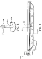
FIG. 6 is a schematic view of the combined structure of a buffer cap and the metal pin.
FIG. 7 is a cross-sectional view of a liquid crystal display according to another embodiment of the present invention.
DETAILED DESCRIPTION OF THE PREFERRED EMBODIMENT
FIG. 3 is an exploded schematic view of a liquid crystal display 200 according to one embodiment of the present invention. The liquid crystal display 200 comprises a liquid crystal panel 206 for producing an image and a direct type backlight unit 202 for emitting light to the liquid crystal panel 206. A set of optical films 204 is disposed between the backlight unit 202 and the liquid crystal panel 206. The set of optical films 204 includes a diffuser 204 a disposed upon the backlight unit 202 and a plurality of optical sheets, such as a diffusing sheet 204 b and a prism sheet 204 c, disposed on the diffuser 204 a. The diffuser 204 a is disposed upon the backlight unit 202 and typically made of half-transparent polyethylene terephthalate (PET), polyethylene terephthalate, or polycarbonate for further evenly diffusing the light emitted from the backlight unit 202. Then, the diffused light will pass through the plurality of optical sheet, such as the diffusing sheet 204 b and the prism sheet 204 c, and finally reach the liquid crystal panel 206. A frame 208 is disposed upon the liquid crystal panel 206 for fixing the liquid crystal panel 206 and the set of optical films 204 upon the backlight unit 202.
Now referring to FIG. 4, it is a cross-sectional view of the assembled liquid crystal display taken along line B—B in FIG. 3. The backlight unit 202 comprises a metal housing 203, which defines a cavity 205 for accommodating a plurality of lamps 210 such as cold cathode fluorescent lamps (CCFL). The lamps 210 are spacedly disposed on the cavity 205 and positioned under the set of optical films 204, so as to emit light to the set of optical films 204 and then distribute it uniformly over the surface of the liquid crystal panel 206 while the light passes through the set of optical films 204.
The metal housing 203 includes a metal base 203 a having a metal supporting pin 212 disposed thereon and protruding upwardly therefrom for supporting the diffuser 204 a. The metal supporting pin 212 is formed integrally on the metal base 203 a so as to form a firmly fixed structure, and therefore provided with higher reliability.
FIGS. 5 a and 5 b are respectively an enlarged perspective view and an enlarged cross-sectional view for illustrating how the metal supporting pin is to be formed on the metal base. The supporting pin 212 is a cylindrical metal pin with a polygonal base 212 a and the metal base 203 a has a hole 207 before the metal supporting pin 212 is formed integrally on the metal base 203 a. Preferably, the diameter of the cylindrical metal pin is about 1.0 mm to 1.5 mm. The hole 207 tapers off from the bottom surface toward the top surface of the metal base 203 a (as shown in 5 b), and the cylindrical metal pin 212 is to be inserted into the hole 207 from the bottom surface and then formed integrally on the metal base 203 a by the press forming process.
The metal supporting pin 212 according to the present invention preferably has a buffer element disposed on its top so as to prevent itself from damaging the diffuser 204 a. The buffer element is preferably made of a material of which the hardness is lower than that of the diffuser 204 a.
FIG. 6 is a schematic view of the combined structure of a buffer cap 214 and the metal supporting pin 212. The buffer element can be made into the buffer cap 214 shown in FIG. 6, and the buffer cap 214 is preferably white and made of silicon rubber. The buffer cap 214 is a cap having a domelike top and defines a combination hole 214 a for capping the top of the metal supporting pin 212. FIG. 7 is a cross-sectional view of a liquid crystal display 200 according to another embodiment of the present invention. The top of the metal supporting pin 212 is capped with the buffer cap 214 shown in FIG. 6, such that the metal supporting pin 212 is prevented from directly contacting the diffuser 204 a and thus can be prevented from damaging the diffuser 204 a by such a manner.
It should be noted that the presently disclosed embodiments are to be considered in all respects as illustrative and not restrictive. For example, there can be a plurality of metal supporting pins 212 to be evenly formed on the metal base 203 a such that each lamp 210 can keep a fixed distance from the diffuser 104 a. In addition, the metal supporting pin 212 can be formed in any shapes (such as conical shape) and therefore should not be limited to the cylindrical shape as illustrated in above embodiments of the present invention.
According to the direct type backlight unit of the present invention, the metal supporting pin for supporting the diffuser is formed integrally on the metal housing of the direct type backlight unit by the press forming process so as to solve the conventional reliability problem of the supporting pin. Further, the metal supporting pin has a buffer element, which is preferably a white buffer cap, disposed thereon so as to prevent the metal supporting pin from damaging the optical film supported thereby.
In addition, one feature of the present invention is that a supporting pin for supporting an optical film is formed integrally on the housing of a backlight unit and has a buffer element disposed thereon so as to prevent itself from damaging the supported optical film. Therefore, it should be understood that the material of the supporting pin and the housing of the backlight unit in the embodiment of the present invention are not limited to metal, and the uses of other materials such as plastic, resin or some hardened substances are also falling into the scope of the present invention.
Although the invention has been explained in relation to its preferred embodiment, it is not used to limit the invention. It is to be understood that many other possible modifications and variations can be made by those skilled in the art without departing from the spirit and scope of the invention as hereinafter claimed.