US7134612B2 - Support for dispensing device - Google Patents
Support for dispensing device Download PDFInfo
- Publication number
- US7134612B2 US7134612B2 US10/710,306 US71030604A US7134612B2 US 7134612 B2 US7134612 B2 US 7134612B2 US 71030604 A US71030604 A US 71030604A US 7134612 B2 US7134612 B2 US 7134612B2
- Authority
- US
- United States
- Prior art keywords
- support member
- support
- dispensing device
- frame member
- frame
- Prior art date
- Legal status (The legal status is an assumption and is not a legal conclusion. Google has not performed a legal analysis and makes no representation as to the accuracy of the status listed.)
- Expired - Fee Related, expires
Links
- 239000007788 liquid Substances 0.000 claims abstract description 13
- 239000000463 material Substances 0.000 description 6
- XLYOFNOQVPJJNP-UHFFFAOYSA-N water Substances O XLYOFNOQVPJJNP-UHFFFAOYSA-N 0.000 description 3
- 239000004743 Polypropylene Substances 0.000 description 2
- 229910000831 Steel Inorganic materials 0.000 description 2
- 235000008504 concentrate Nutrition 0.000 description 2
- 239000012141 concentrate Substances 0.000 description 2
- -1 polypropylene Polymers 0.000 description 2
- 229920001155 polypropylene Polymers 0.000 description 2
- 239000010959 steel Substances 0.000 description 2
- 239000004677 Nylon Substances 0.000 description 1
- 125000000218 acetic acid group Chemical group C(C)(=O)* 0.000 description 1
- 238000004140 cleaning Methods 0.000 description 1
- 230000000295 complement effect Effects 0.000 description 1
- 239000000645 desinfectant Substances 0.000 description 1
- 239000011521 glass Substances 0.000 description 1
- 238000007373 indentation Methods 0.000 description 1
- 238000009434 installation Methods 0.000 description 1
- 235000014666 liquid concentrate Nutrition 0.000 description 1
- 239000011344 liquid material Substances 0.000 description 1
- 238000012986 modification Methods 0.000 description 1
- 230000004048 modification Effects 0.000 description 1
- 229920001778 nylon Polymers 0.000 description 1
- 229920005989 resin Polymers 0.000 description 1
- 239000011347 resin Substances 0.000 description 1
- 229910001220 stainless steel Inorganic materials 0.000 description 1
- 239000010935 stainless steel Substances 0.000 description 1
Images


Classifications
-
- B—PERFORMING OPERATIONS; TRANSPORTING
- B67—OPENING, CLOSING OR CLEANING BOTTLES, JARS OR SIMILAR CONTAINERS; LIQUID HANDLING
- B67D—DISPENSING, DELIVERING OR TRANSFERRING LIQUIDS, NOT OTHERWISE PROVIDED FOR
- B67D7/00—Apparatus or devices for transferring liquids from bulk storage containers or reservoirs into vehicles or into portable containers, e.g. for retail sale purposes
- B67D7/06—Details or accessories
- B67D7/74—Devices for mixing two or more different liquids to be transferred
- B67D7/741—Devices for mixing two or more different liquids to be transferred mechanically operated
-
- B—PERFORMING OPERATIONS; TRANSPORTING
- B05—SPRAYING OR ATOMISING IN GENERAL; APPLYING FLUENT MATERIALS TO SURFACES, IN GENERAL
- B05B—SPRAYING APPARATUS; ATOMISING APPARATUS; NOZZLES
- B05B15/00—Details of spraying plant or spraying apparatus not otherwise provided for; Accessories
- B05B15/60—Arrangements for mounting, supporting or holding spraying apparatus
-
- B—PERFORMING OPERATIONS; TRANSPORTING
- B67—OPENING, CLOSING OR CLEANING BOTTLES, JARS OR SIMILAR CONTAINERS; LIQUID HANDLING
- B67D—DISPENSING, DELIVERING OR TRANSFERRING LIQUIDS, NOT OTHERWISE PROVIDED FOR
- B67D7/00—Apparatus or devices for transferring liquids from bulk storage containers or reservoirs into vehicles or into portable containers, e.g. for retail sale purposes
- B67D7/005—Spouts
-
- B—PERFORMING OPERATIONS; TRANSPORTING
- B67—OPENING, CLOSING OR CLEANING BOTTLES, JARS OR SIMILAR CONTAINERS; LIQUID HANDLING
- B67D—DISPENSING, DELIVERING OR TRANSFERRING LIQUIDS, NOT OTHERWISE PROVIDED FOR
- B67D7/00—Apparatus or devices for transferring liquids from bulk storage containers or reservoirs into vehicles or into portable containers, e.g. for retail sale purposes
- B67D7/02—Apparatus or devices for transferring liquids from bulk storage containers or reservoirs into vehicles or into portable containers, e.g. for retail sale purposes for transferring liquids other than fuel or lubricants
-
- B—PERFORMING OPERATIONS; TRANSPORTING
- B67—OPENING, CLOSING OR CLEANING BOTTLES, JARS OR SIMILAR CONTAINERS; LIQUID HANDLING
- B67D—DISPENSING, DELIVERING OR TRANSFERRING LIQUIDS, NOT OTHERWISE PROVIDED FOR
- B67D7/00—Apparatus or devices for transferring liquids from bulk storage containers or reservoirs into vehicles or into portable containers, e.g. for retail sale purposes
- B67D7/06—Details or accessories
- B67D7/42—Filling nozzles
- B67D7/423—Filling nozzles specially adapted for blending several fluids
-
- B—PERFORMING OPERATIONS; TRANSPORTING
- B67—OPENING, CLOSING OR CLEANING BOTTLES, JARS OR SIMILAR CONTAINERS; LIQUID HANDLING
- B67D—DISPENSING, DELIVERING OR TRANSFERRING LIQUIDS, NOT OTHERWISE PROVIDED FOR
- B67D7/00—Apparatus or devices for transferring liquids from bulk storage containers or reservoirs into vehicles or into portable containers, e.g. for retail sale purposes
- B67D7/06—Details or accessories
- B67D7/74—Devices for mixing two or more different liquids to be transferred
-
- B—PERFORMING OPERATIONS; TRANSPORTING
- B67—OPENING, CLOSING OR CLEANING BOTTLES, JARS OR SIMILAR CONTAINERS; LIQUID HANDLING
- B67D—DISPENSING, DELIVERING OR TRANSFERRING LIQUIDS, NOT OTHERWISE PROVIDED FOR
- B67D2210/00—Indexing scheme relating to aspects and details of apparatus or devices for dispensing beverages on draught or for controlling flow of liquids under gravity from storage containers for dispensing purposes
- B67D2210/00028—Constructional details
- B67D2210/00128—Constructional details relating to outdoor use; movable; portable
- B67D2210/00131—Constructional details relating to outdoor use; movable; portable wearable by a person, e.g. as a backpack or helmet
Definitions
- This invention relates to a support for a hand held dispensing device. More particularly, it relates to a support for a hand held liquid dispensing device which includes a container support and facilitates the filling of a container as well as affords connection to a dispensing hose for filling a bucket.
- the prior art does not provide a support or holder for hand held liquid dispensing devices. There is a need for such an apparatus.
- the type of hand held liquid dispensing devices concerned with in this invention are those which are attached to a hose and a container with liquid concentrate. Such a device is described in U.S. Pat. No. 6,708,901, which teachings are incorporated herein by reference.
- This type of dispenser dispenses cleaning, disinfectants and similar types of materials. After use, it is desirable to have a place to store the dispenser. It would also be desirable to have a storage apparatus which would also allow for the filling of containers and buckets with diluted concentrate while the dispenser is being stored.
- the present invention provides an apparatus for supporting a hand held liquid dispensing device.
- the apparatus includes a first support member for receiving a nozzle portion of the dispensing device.
- the first support member includes a cavity.
- first support members there are two oppositely disposed first support members connected to the frame member.
- the first support member is defined by a platform having a cavity for placement of a dispenser nozzle therein and the second support member is defined by a foot portion, the foot portion supported by the frame and pivotally connected to the frame member.
- the frame member is defined by a first portion extending in a first direction and a second portion extending essentially at right angles to the first portion with the second portion connected to the two oppositely disposed second support members.
- the invention provides a combined hand held dispenser device and apparatus for supporting the device.
- the frame member includes a third support member as well as a side portion connected to the third support member with the side portion angling inwardly from the third support member toward the first support member.
- FIG. 1 is a perspective view of the support for dispensing device of the invention as well as two dispensing devices;
- FIG. 2 is a front view of the support for a dispensing device showing the filling of a bucket
- FIG. 3 is a top view of the support for a dispensing device
- FIG. 4 is a front view of the support for a dispensing device without any attachments
- FIG. 5 is a side view of the support for a dispensing device
- FIG. 6 is a bottom view of the support for a dispensing device
- FIG. 7 is a front view with a portion shown in phantom illustrating the supporting structure for the dispensing device
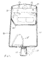
- FIG. 8 is a perspective view of a second embodiment of the support for a dispensing device
- FIG. 9 is a front view of the embodiment shown in FIG. 8 with a dispensing device and bottle supported thereon;
- FIG. 10 is a view similar to FIG. 9 illustrating the connection of the dispensing device to a hose.
- the support apparatus 10 is illustrated in conjunction with a dispensing device 12 .
- the dispensing device was previously referred to above as described in U.S. Pat. No. 6,708,901.
- the support apparatus 10 includes a platform 14 and a back wall 16 , as well as cavities 18 providing a first support member which receive the spout 22 of the dispensing device 12 .
- the platform 14 has indented panels 13 which afford an area for placement of product identification labels to indicate the materials being dispensed from the dispenser bottle 55 .
- foot portions 25 and 27 providing a second support member which are pivotally attached to a frame 30 for purposes of supporting containers such as bottle 33 and provide a drip tray when a bottle is not present.
- foot portions 25 and 27 have indentations 35 so as to accommodate the bottoms of a bottle such as 33 .
- a hose 40 which is attached to the dispensing tube 15 of dispenser 12 for the purpose of filling bucket 38 .
- the frame 30 includes a second portion 42 extending essentially at a right angle to a vertical first portion 46 of frame 30 .
- This portion 42 supports the foot portions 25 and 27 which they are pivotally attached to frame 30 .
- frame 30 includes an additional U-shaped portion 44 supporting the platform 14 as by contact with the projections 48 .
- FIGS. 8–10 illustrate a second embodiment generally 10 A of the support apparatus.
- the same reference numerals are employed as previously with respect to similar elements and embodiment 10 , except they include the “A” suffix.
- One of the differences between support apparatus 10 and 10 A is an additional third support member 60 A and the side portions 62 A of the frame 30 A. It should be noted that the side portions 62 A angle inwardly in a direction from the third support member 60 A toward the first support member in the form of platform 14 A. This provides additional support for dispenser bottle 55 A in addition to the support provided by the spout 22 A positioned in cavity 18 A.
- Another difference is the funnel 64 A. This affords efficient transfer of liquid material from the dispensing device 12 A into the hose 40 A for bucket filling.
- support apparatus 10 is mounted to a wall such as by the mounting screws 52 .
- Dispensing devices 12 are supported by the support apparatus, such as by the placement of spouts 22 in the cavities 18 .
- Water supply hoses (not shown) are connected to the connectors 54 such as by means of complementary disconnect devices (not shown).
- When it is desired to fill bottle 33 it is placed on foot portion 27 .
- the bottle 33 can then be easily filled from the dispensing device 12 with a solution of the concentrate from the dispenser bottle 55 and the water.
- the foot portion 25 is pivoted to an away position such as shown in FIG. 2 .
- foot portion 25 will assume a similar position as shown for foot portion 27 . In a like manner, it will be supported by the frame portion 42 .
- support apparatus 10 A The operation of support apparatus 10 A is essentially the same as that described for support apparatus 10 .
- the major difference, as previously described, is the support of the bottle 55 A by the support members 60 A and the side portions 62 A and the presence of the funnel member 64 A for bucket filling. In those instances where the bottle 55 A is not of a size to rest on support member 60 A, a smaller bottle would be supported by the angled side portions 62 A.
- the preferred material for fabricating platform 14 , as well as foot portions 25 and 27 is polypropylene. However, other materials such as acetyl resins and glass filled polypropylene could also be employed.
- Frame member 30 is composed of a steel bar with frame portion 42 being welded thereto as is portion 44 and the bar member 50 .
- the preferred material for composing frame 30 is steel. However, other materials such as stainless steel and nylon could also be utilized. While the support apparatus 10 has been illustrated for use with the foot portions 25 and 27 which could support two bottles 33 and alternatively provide for a connection support to the hose 40 , it is readily apparent that the support apparatus could be designed for supporting only a single dispensing device and a single container 33 placed on foot portion 27 .
Landscapes
- Engineering & Computer Science (AREA)
- Mechanical Engineering (AREA)
- Basic Packing Technique (AREA)
- Filling Of Jars Or Cans And Processes For Cleaning And Sealing Jars (AREA)
- Supply Of Fluid Materials To The Packaging Location (AREA)
- Devices For Dispensing Beverages (AREA)
- Details Or Accessories Of Spraying Plant Or Apparatus (AREA)
- Jet Pumps And Other Pumps (AREA)
Abstract
Description
Claims (27)
Priority Applications (14)
| Application Number | Priority Date | Filing Date | Title |
|---|---|---|---|
| US10/710,306 US7134612B2 (en) | 2003-12-19 | 2004-07-01 | Support for dispensing device |
| PCT/US2004/042658 WO2005063610A1 (en) | 2003-12-19 | 2004-12-17 | Support for dispensing device |
| ES04814799T ES2302072T3 (en) | 2003-12-19 | 2004-12-17 | SUPPORT FOR DISPENSING DEVICE. |
| KR1020067011868A KR20060126652A (en) | 2003-12-19 | 2004-12-17 | Support for dispensing device |
| PT04814799T PT1699732E (en) | 2003-12-19 | 2004-12-17 | Support for dispensing device |
| AT04814799T ATE387405T1 (en) | 2003-12-19 | 2004-12-17 | SUPPORT FOR DISPENSING DEVICE |
| CA002548314A CA2548314A1 (en) | 2003-12-19 | 2004-12-17 | Support for dispensing device |
| BRPI0417091-1A BRPI0417091A (en) | 2003-12-19 | 2004-12-17 | distributor device support |
| JP2006545530A JP4885732B2 (en) | 2003-12-19 | 2004-12-17 | Support for dispensing devices |
| MXPA06006934A MXPA06006934A (en) | 2003-12-19 | 2004-12-17 | Support for dispensing device. |
| AU2004308917A AU2004308917A1 (en) | 2003-12-19 | 2004-12-17 | Support for dispensing device |
| PL04814799T PL1699732T3 (en) | 2003-12-19 | 2004-12-17 | Support for dispensing device |
| EP04814799A EP1699732B1 (en) | 2003-12-19 | 2004-12-17 | Support for dispensing device |
| DE602004012157T DE602004012157T2 (en) | 2003-12-19 | 2004-12-17 | SUPPORT FOR DISTRIBUTION DEVICE |
Applications Claiming Priority (2)
| Application Number | Priority Date | Filing Date | Title |
|---|---|---|---|
| US10/707,533 US20050133622A1 (en) | 2003-12-19 | 2003-12-19 | Support for dispensing device |
| US10/710,306 US7134612B2 (en) | 2003-12-19 | 2004-07-01 | Support for dispensing device |
Related Parent Applications (1)
| Application Number | Title | Priority Date | Filing Date |
|---|---|---|---|
| US10/707,533 Continuation-In-Part US20050133622A1 (en) | 2003-12-19 | 2003-12-19 | Support for dispensing device |
Publications (2)
| Publication Number | Publication Date |
|---|---|
| US20050145719A1 US20050145719A1 (en) | 2005-07-07 |
| US7134612B2 true US7134612B2 (en) | 2006-11-14 |
Family
ID=34677027
Family Applications (2)
| Application Number | Title | Priority Date | Filing Date |
|---|---|---|---|
| US10/707,533 Abandoned US20050133622A1 (en) | 2003-12-19 | 2003-12-19 | Support for dispensing device |
| US10/710,306 Expired - Fee Related US7134612B2 (en) | 2003-12-19 | 2004-07-01 | Support for dispensing device |
Family Applications Before (1)
| Application Number | Title | Priority Date | Filing Date |
|---|---|---|---|
| US10/707,533 Abandoned US20050133622A1 (en) | 2003-12-19 | 2003-12-19 | Support for dispensing device |
Country Status (4)
| Country | Link |
|---|---|
| US (2) | US20050133622A1 (en) |
| JP (1) | JP4885732B2 (en) |
| CN (1) | CN1890172A (en) |
| PT (1) | PT1699732E (en) |
Cited By (4)
| Publication number | Priority date | Publication date | Assignee | Title |
|---|---|---|---|---|
| US8646368B1 (en) * | 2008-04-22 | 2014-02-11 | Kreg Enterprises, Inc. | Crown molding cutting jig |
| USD749192S1 (en) | 2014-08-05 | 2016-02-09 | Chapin Manufacturing, Inc. | Battery operated motor driven backpack sprayer |
| USD759786S1 (en) | 2015-05-15 | 2016-06-21 | Chapin Manufacturing, Inc. | Tank for a backpack sprayer |
| US10562052B2 (en) | 2014-08-05 | 2020-02-18 | Chapin Manufactuing, Inc. | Battery operated backpack sprayer |
Families Citing this family (3)
| Publication number | Priority date | Publication date | Assignee | Title |
|---|---|---|---|---|
| JP5002369B2 (en) * | 2007-08-17 | 2012-08-15 | 大日本スクリーン製造株式会社 | Nozzle storage device and coating device |
| WO2013161421A1 (en) * | 2012-04-25 | 2013-10-31 | 株式会社タカギ | Device for diluting and sprinkling liquid agent |
| US9468892B2 (en) * | 2014-02-07 | 2016-10-18 | Hydra-Flex, Inc. | Modular chemical dispensing assembly |
Citations (11)
| Publication number | Priority date | Publication date | Assignee | Title |
|---|---|---|---|---|
| DE8701170U1 (en) | 1987-01-24 | 1987-04-02 | Pelzer, Ernst-Hermann, 3201 Diekholzen | Beverage dispensing device |
| US4681244A (en) | 1986-04-30 | 1987-07-21 | Geddie John D | Portable bar |
| EP0366444A2 (en) | 1988-10-25 | 1990-05-02 | Robert Billet Promotions, Inc. | Portable beverage dispenser |
| US5408936A (en) * | 1993-12-28 | 1995-04-25 | Tseng; Chun-Chu | Rack assembly |
| US5497967A (en) * | 1993-03-10 | 1996-03-12 | Gantois; Johan | Bicycle repair stand |
| WO1997026210A2 (en) | 1996-01-19 | 1997-07-24 | S.C. Johnson & Son, Inc. | Docking station and bottle system |
| US5651398A (en) * | 1996-03-29 | 1997-07-29 | Ecolab Inc. | Chemical solution filling system |
| US6158673A (en) * | 1998-03-02 | 2000-12-12 | Ecolab Inc. | Portable unit wall unit dispensers and method of dispensing |
| US6363977B1 (en) | 2000-09-12 | 2002-04-02 | Knlght, Inc. | Container filling apparatus |
| US20020092925A1 (en) | 2001-01-12 | 2002-07-18 | Hubmann Curtis H. | Multiple function dispenser |
| US20020148907A1 (en) * | 2001-02-01 | 2002-10-17 | Jung You | Portable spray car wash device |
Family Cites Families (11)
| Publication number | Priority date | Publication date | Assignee | Title |
|---|---|---|---|---|
| US3876114A (en) * | 1973-02-14 | 1975-04-08 | Artek Ind Inc | Multiple ingredient metering, mixing and dispensing apparatus |
| JPS5847786B2 (en) * | 1977-05-26 | 1983-10-25 | 富士通株式会社 | Magnetic bubble drive coil |
| US5031799A (en) * | 1989-02-17 | 1991-07-16 | Charlie O Company, Inc. | Seltzer dispenser for use with a home soda dispensing system |
| JPH09207915A (en) * | 1996-01-31 | 1997-08-12 | Kunihiro Sakamoto | Liquid container and supporting utensil of filling nozzle |
| US5782109A (en) * | 1996-05-06 | 1998-07-21 | Ecolab Inc. | Dispenser |
| JPH10287395A (en) * | 1997-04-14 | 1998-10-27 | Akihiko Shimizu | Cock device for dispensing fixed quantity of liquid such as oils |
| US6279836B1 (en) * | 1998-03-02 | 2001-08-28 | Ecolab Inc. | Portable unit and wall unit dispensers and method of dispensing with timer |
| US5996907A (en) * | 1998-03-02 | 1999-12-07 | Ecolab Inc. | Portable wash and rinse system with dilution |
| JP2000229697A (en) * | 1999-02-12 | 2000-08-22 | Hoshizaki Electric Co Ltd | Drink dispenser |
| JP3715569B2 (en) * | 2001-12-11 | 2005-11-09 | 新宅工業株式会社 | Beverage supply method and apparatus |
| JP4038382B2 (en) * | 2002-03-08 | 2008-01-23 | 要蔵 森 | Poly tank pouring device |
-
2003
- 2003-12-19 US US10/707,533 patent/US20050133622A1/en not_active Abandoned
-
2004
- 2004-07-01 US US10/710,306 patent/US7134612B2/en not_active Expired - Fee Related
- 2004-12-17 CN CNA2004800368018A patent/CN1890172A/en active Pending
- 2004-12-17 JP JP2006545530A patent/JP4885732B2/en not_active Expired - Fee Related
- 2004-12-17 PT PT04814799T patent/PT1699732E/en unknown
Patent Citations (14)
| Publication number | Priority date | Publication date | Assignee | Title |
|---|---|---|---|---|
| US4681244A (en) | 1986-04-30 | 1987-07-21 | Geddie John D | Portable bar |
| DE8701170U1 (en) | 1987-01-24 | 1987-04-02 | Pelzer, Ernst-Hermann, 3201 Diekholzen | Beverage dispensing device |
| EP0366444A2 (en) | 1988-10-25 | 1990-05-02 | Robert Billet Promotions, Inc. | Portable beverage dispenser |
| US5497967A (en) * | 1993-03-10 | 1996-03-12 | Gantois; Johan | Bicycle repair stand |
| US5408936A (en) * | 1993-12-28 | 1995-04-25 | Tseng; Chun-Chu | Rack assembly |
| WO1997026210A2 (en) | 1996-01-19 | 1997-07-24 | S.C. Johnson & Son, Inc. | Docking station and bottle system |
| US5651398A (en) * | 1996-03-29 | 1997-07-29 | Ecolab Inc. | Chemical solution filling system |
| US6158673A (en) * | 1998-03-02 | 2000-12-12 | Ecolab Inc. | Portable unit wall unit dispensers and method of dispensing |
| US6363977B1 (en) | 2000-09-12 | 2002-04-02 | Knlght, Inc. | Container filling apparatus |
| US20020040737A1 (en) | 2000-09-12 | 2002-04-11 | Beldham Paul M. | Container filling apparatus and methods |
| US6532998B2 (en) | 2000-09-12 | 2003-03-18 | Knight, Inc. | Container filling apparatus and methods |
| US20030192618A1 (en) | 2000-09-12 | 2003-10-16 | Knight, Inc. | Container filling apparatus and methods |
| US20020092925A1 (en) | 2001-01-12 | 2002-07-18 | Hubmann Curtis H. | Multiple function dispenser |
| US20020148907A1 (en) * | 2001-02-01 | 2002-10-17 | Jung You | Portable spray car wash device |
Cited By (4)
| Publication number | Priority date | Publication date | Assignee | Title |
|---|---|---|---|---|
| US8646368B1 (en) * | 2008-04-22 | 2014-02-11 | Kreg Enterprises, Inc. | Crown molding cutting jig |
| USD749192S1 (en) | 2014-08-05 | 2016-02-09 | Chapin Manufacturing, Inc. | Battery operated motor driven backpack sprayer |
| US10562052B2 (en) | 2014-08-05 | 2020-02-18 | Chapin Manufactuing, Inc. | Battery operated backpack sprayer |
| USD759786S1 (en) | 2015-05-15 | 2016-06-21 | Chapin Manufacturing, Inc. | Tank for a backpack sprayer |
Also Published As
| Publication number | Publication date |
|---|---|
| US20050145719A1 (en) | 2005-07-07 |
| US20050133622A1 (en) | 2005-06-23 |
| JP4885732B2 (en) | 2012-02-29 |
| JP2007529296A (en) | 2007-10-25 |
| PT1699732E (en) | 2008-04-09 |
| CN1890172A (en) | 2007-01-03 |
Similar Documents
| Publication | Publication Date | Title |
|---|---|---|
| US7395842B2 (en) | Apparatus for filling and refilling a flexible container | |
| US5651398A (en) | Chemical solution filling system | |
| US6435379B2 (en) | Bottled liquid dispensers | |
| US6540111B2 (en) | Bottled soda dispenser | |
| CA1221944A (en) | Beverage dispenser | |
| US7134612B2 (en) | Support for dispensing device | |
| US6039214A (en) | Material dispensing system | |
| US7520447B2 (en) | Spray bottle | |
| US6325251B1 (en) | Combination fuel tank and tool holder apparatus | |
| US5184476A (en) | Counter-height water dispenser | |
| US20180216278A1 (en) | Attachable cup holder | |
| EP1699732B1 (en) | Support for dispensing device | |
| US6848596B2 (en) | Upright product outlet bag evacuation packaging | |
| US20110259949A1 (en) | Solid Food Product Container Dispenser | |
| US5553723A (en) | Rack system for displaying and dispensing candy | |
| US6382579B1 (en) | Support system for an inverted toothpaste tube | |
| US7992586B1 (en) | Receptacle for catching and retaining unwanted liquids | |
| US20100072343A1 (en) | Multiple-compartmented platform capable of holding dispensers and interchangeable towel holders | |
| US4640483A (en) | Platform device | |
| EP0524193A1 (en) | A hot beverage dispensing arrangement. | |
| US20230365300A1 (en) | Bottle and stand for removing contents from bottle | |
| US20100187373A1 (en) | Pedestal dispenser | |
| JPH08151100A (en) | Device for taking out liquid in small quantities |
Legal Events
| Date | Code | Title | Description |
|---|---|---|---|
| AS | Assignment |
Owner name: JOHNSONDIVERSEY, INC., WISCONSIN Free format text: ASSIGNMENT OF ASSIGNORS INTEREST;ASSIGNORS:BERTUCCI, MICHAEL H.;LANG, CHRISTOPHER F.;SCHILLER, STEVEN E.;REEL/FRAME:014802/0384;SIGNING DATES FROM 20040629 TO 20040701 |
|
| AS | Assignment |
Owner name: CITIBANK, N.A., AS ADMINISTRATIVE AGENT,NEW YORK Free format text: SECURITY AGREEMENT;ASSIGNOR:JOHNSONDIVERSEY, INC.;REEL/FRAME:023814/0701 Effective date: 20091124 Owner name: CITIBANK, N.A., AS ADMINISTRATIVE AGENT, NEW YORK Free format text: SECURITY AGREEMENT;ASSIGNOR:JOHNSONDIVERSEY, INC.;REEL/FRAME:023814/0701 Effective date: 20091124 |
|
| AS | Assignment |
Owner name: DIVERSEY, INC.,WISCONSIN Free format text: CHANGE OF NAME;ASSIGNOR:JOHNSONDIVERSEY, INC.;REEL/FRAME:024066/0919 Effective date: 20100301 Owner name: DIVERSEY, INC., WISCONSIN Free format text: CHANGE OF NAME;ASSIGNOR:JOHNSONDIVERSEY, INC.;REEL/FRAME:024066/0919 Effective date: 20100301 |
|
| FPAY | Fee payment |
Year of fee payment: 4 |
|
| AS | Assignment |
Owner name: DIVERSEY, INC. (FORMERLY KNOWN AS JOHNSONDIVERSEY, Free format text: RELEASE BY SECURED PARTY;ASSIGNOR:CITIBANK, N.A., AS ADMINISTRATIVE AGENT;REEL/FRAME:027618/0044 Effective date: 20111003 |
|
| FPAY | Fee payment |
Year of fee payment: 8 |
|
| AS | Assignment |
Owner name: CREDIT SUISSE AG, CAYMAN ISLANDS BRANCH, AS COLLATERAL AGENT, NEW YORK Free format text: SECURITY AGREEMENT;ASSIGNORS:DIVERSEY, INC.;THE BUTCHER COMPANY;REEL/FRAME:045300/0141 Effective date: 20170906 Owner name: CREDIT SUISSE AG, CAYMAN ISLANDS BRANCH, AS COLLAT Free format text: SECURITY AGREEMENT;ASSIGNORS:DIVERSEY, INC.;THE BUTCHER COMPANY;REEL/FRAME:045300/0141 Effective date: 20170906 |
|
| FEPP | Fee payment procedure |
Free format text: MAINTENANCE FEE REMINDER MAILED (ORIGINAL EVENT CODE: REM.) |
|
| LAPS | Lapse for failure to pay maintenance fees |
Free format text: PATENT EXPIRED FOR FAILURE TO PAY MAINTENANCE FEES (ORIGINAL EVENT CODE: EXP.); ENTITY STATUS OF PATENT OWNER: LARGE ENTITY |
|
| STCH | Information on status: patent discontinuation |
Free format text: PATENT EXPIRED DUE TO NONPAYMENT OF MAINTENANCE FEES UNDER 37 CFR 1.362 |
|
| FP | Lapsed due to failure to pay maintenance fee |
Effective date: 20181114 |
|
| AS | Assignment |
Owner name: THE BUTCHER COMPANY, NORTH CAROLINA Free format text: RELEASE OF SECURITY AGREEMENT REEL/FRAME 045300/0141;ASSIGNOR:CREDIT SUISSE AG, CAYMAN ISLANDS BRANCH;REEL/FRAME:064236/0722 Effective date: 20230705 Owner name: DIVERSEY, INC., NORTH CAROLINA Free format text: RELEASE OF SECURITY AGREEMENT REEL/FRAME 045300/0141;ASSIGNOR:CREDIT SUISSE AG, CAYMAN ISLANDS BRANCH;REEL/FRAME:064236/0722 Effective date: 20230705 |