US7134359B2 - Adjustable handle assembly for a personal mobility vehicle - Google Patents
Adjustable handle assembly for a personal mobility vehicle Download PDFInfo
- Publication number
- US7134359B2 US7134359B2 US10/668,325 US66832503A US7134359B2 US 7134359 B2 US7134359 B2 US 7134359B2 US 66832503 A US66832503 A US 66832503A US 7134359 B2 US7134359 B2 US 7134359B2
- Authority
- US
- United States
- Prior art keywords
- sliding block
- pivot post
- bracket
- handle assembly
- adjustable handle
- Prior art date
- Legal status (The legal status is an assumption and is not a legal conclusion. Google has not performed a legal analysis and makes no representation as to the accuracy of the status listed.)
- Expired - Fee Related, expires
Links
Images


Classifications
-
- B—PERFORMING OPERATIONS; TRANSPORTING
- B62—LAND VEHICLES FOR TRAVELLING OTHERWISE THAN ON RAILS
- B62K—CYCLES; CYCLE FRAMES; CYCLE STEERING DEVICES; RIDER-OPERATED TERMINAL CONTROLS SPECIALLY ADAPTED FOR CYCLES; CYCLE AXLE SUSPENSIONS; CYCLE SIDE-CARS, FORECARS, OR THE LIKE
- B62K21/00—Steering devices
- B62K21/12—Handlebars; Handlebar stems
- B62K21/16—Handlebars; Handlebar stems having adjustable parts therein
-
- A—HUMAN NECESSITIES
- A61—MEDICAL OR VETERINARY SCIENCE; HYGIENE
- A61G—TRANSPORT, PERSONAL CONVEYANCES, OR ACCOMMODATION SPECIALLY ADAPTED FOR PATIENTS OR DISABLED PERSONS; OPERATING TABLES OR CHAIRS; CHAIRS FOR DENTISTRY; FUNERAL DEVICES
- A61G5/00—Chairs or personal conveyances specially adapted for patients or disabled persons, e.g. wheelchairs
- A61G5/10—Parts, details or accessories
- A61G5/1051—Arrangements for steering
-
- A—HUMAN NECESSITIES
- A61—MEDICAL OR VETERINARY SCIENCE; HYGIENE
- A61G—TRANSPORT, PERSONAL CONVEYANCES, OR ACCOMMODATION SPECIALLY ADAPTED FOR PATIENTS OR DISABLED PERSONS; OPERATING TABLES OR CHAIRS; CHAIRS FOR DENTISTRY; FUNERAL DEVICES
- A61G5/00—Chairs or personal conveyances specially adapted for patients or disabled persons, e.g. wheelchairs
- A61G5/04—Chairs or personal conveyances specially adapted for patients or disabled persons, e.g. wheelchairs motor-driven
-
- A—HUMAN NECESSITIES
- A61—MEDICAL OR VETERINARY SCIENCE; HYGIENE
- A61G—TRANSPORT, PERSONAL CONVEYANCES, OR ACCOMMODATION SPECIALLY ADAPTED FOR PATIENTS OR DISABLED PERSONS; OPERATING TABLES OR CHAIRS; CHAIRS FOR DENTISTRY; FUNERAL DEVICES
- A61G5/00—Chairs or personal conveyances specially adapted for patients or disabled persons, e.g. wheelchairs
- A61G5/10—Parts, details or accessories
-
- Y—GENERAL TAGGING OF NEW TECHNOLOGICAL DEVELOPMENTS; GENERAL TAGGING OF CROSS-SECTIONAL TECHNOLOGIES SPANNING OVER SEVERAL SECTIONS OF THE IPC; TECHNICAL SUBJECTS COVERED BY FORMER USPC CROSS-REFERENCE ART COLLECTIONS [XRACs] AND DIGESTS
- Y10—TECHNICAL SUBJECTS COVERED BY FORMER USPC
- Y10T—TECHNICAL SUBJECTS COVERED BY FORMER US CLASSIFICATION
- Y10T74/00—Machine element or mechanism
- Y10T74/20—Control lever and linkage systems
- Y10T74/20576—Elements
- Y10T74/20732—Handles
- Y10T74/2078—Handle bars
- Y10T74/20792—Folding or adjustable
Definitions
- Personal mobility vehicles such as electric vehicles, aid people who are handicapped or elderly in moving from one place to another.
- a personal mobility vehicle typically has a chassis with wheels, a handle mounted on the chassis and a seat mounted on the chassis on which an elderly or handicapped person sits.
- a person sitting on the mobility vehicle controls the direction in which the vehicle moves by turning the handle.
- people's sizes and shapes vary greatly and may affect their ability to turn the handle on the personal mobility vehicle because of the position and angle of the handle. For example, some people are tall and some people are short.
- the present invention provides an adjustable handle assembly for a personal mobility vehicle having a mechanical lock to mitigate or obviate the aforementioned problems.
- the main objective of the invention is to provide an adjustable handle assembly for a personal mobility vehicle, which has a mechanical lock to hold a handle of the vehicle in position and is convenient and easy to use.
- the mechanical lock uses locking wedges and a sliding block that has a bottom annular bevel to press the locking wedges to clamp a pivot post on the adjustable handle assembly.
- the bottom annular bevel abutting the locking wedges that clamp the adjustable pivot post on the adjustable handle assembly to lock the handle in an adjusted position.
- FIG. 1 is a side plan view of a personal mobility vehicle with an adjustable handle assembly in accordance with the present invention
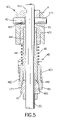
- FIG. 5 is an enlarged front plan view in partial section of the adjustable handle assembly along line 5 — 5 in FIG. 2 ;
- FIG. 6 is an enlarged cross sectional top plan view of the adjustable handle assembly along line 6 — 6 in FIG. 2 .
- the adjustable handle assembly comprises a mounting bracket ( 10 ), an adjusting device (not numbered), a handle ( 21 ) and a mechanical lock ( 40 ).
- the mounting bracket ( 10 ) is attached to the front chassis, is substantially U-shaped and comprises a mounting base ( 11 ) and two perpendicular wings ( 12 ).
- the mounting base ( 11 ) is mounted on the front chassis of the vehicle ( 50 ).
- the wings ( 12 ) are formed perpendicular on and extend upward from the mounting base ( 11 ).
- the mechanical lock ( 40 ) interconnects the two posts ( 20 , 30 ) to hold and lock the two posts ( 20 , 30 ) in a locked position after the posts ( 20 , 30 ) are adjusted.
- the mechanical lock ( 40 ) comprises a stationary bracket ( 41 ), two attachment pins ( 42 ), a bushing bracket ( 43 ), a connecting tube ( 44 ), a sliding block ( 45 ), a biasing member ( 46 ), two locking wedges ( 47 ) and a lever ( 48 ).
- the stationary bracket ( 41 ) is attached securely to and extends out from the primary pivot post ( 20 ) and comprises two mounting plates (not numbered).
- the mounting plates respectively have front ends (not numbered) and rear ends (not numbered).
- the front ends are attached to the primary pivot post ( 20 ) diametrically opposite to each other.
- the rear ends extend out parallel from the primary pivot post ( 20 ).
- Each rear end has a through hole ( 411 ) so the through holes ( 411 ) are aligned.
- the connecting tube ( 44 ) connects to the bushing bracket ( 43 ) and has a top end (not numbered) with an exterior thread ( 441 ), a bottom end (not numbered), an outer periphery (not numbered) and two wedge holes ( 442 ).
- the exterior thread ( 441 ) screws into the bottom threaded hole ( 432 ) to attach the connecting tube ( 44 ) to the bushing bracket ( 43 ).
- the wedge holes ( 442 ) are defined in the outer periphery of the connecting tube ( 44 ) opposite to each other.
- the top end of the secondary pivot post ( 30 ) passes through the connecting tube ( 44 ), the longitudinal passage ( 433 ) of the bushing bracket ( 43 ) and extends out of the longitudinal passage ( 433 ) to mount slidably the secondary pivot post ( 30 ) in the connecting tube ( 44 ) and the bushing bracket ( 43 ).
- the sliding block ( 45 ) is slidably mounted on the outer periphery of the connecting tube ( 44 ) over the wedge holes ( 442 ) and has two outer elongated sliding recesses ( 451 ) and a bottom annular bevel ( 452 ).
- the outer elongated sliding recesses ( 451 ) are formed opposite to each other to hold slidably the lever ( 48 ).
- the basing member ( 46 ) such as a coil spring is mounted between the bushing bracket ( 43 ) and the sliding block ( 45 ) to provide a restitution force to the sliding block ( 45 ).
- the restitution force returns the sliding block ( 45 ) to a locked position when the lever ( 48 ) is released.
- the locking wedges ( 47 ) are movably mounted respectively in the wedge holes ( 442 ) in the connecting tube ( 44 ) and each of the locking wedges ( 47 ) has a inclined surface ( 471 ) slidably abutting the bottom annular bevel ( 452 ) in the sliding block ( 45 ).
- the sliding block ( 45 ) pressed by the basing member ( 46 ) will press the locking wedges ( 47 ) into the wedge holes ( 442 ) to clamp the secondary pivot post ( 30 ).
- the two posts ( 20 , 30 ) are locked and will keep the angles of the posts ( 20 , 30 ) from changing.
- the lever ( 48 ) is pivotally mounted on the primary pivot post ( 20 ), is U-shaped and has two coupling arms ( 481 ). Each arm ( 481 ) is pivotally mounted on the primary pivot post ( 20 ) and has a pair of sliding lobes ( 482 ) that are slidably mounted in the outer elongated sliding recesses ( 451 ) in the sliding block ( 45 ).
- the lever ( 48 ) is pivoted upward to move the sliding block ( 45 ) up to the unlocked position and simultaneously compress the basing member ( 46 ) and create the restitution force.
- the bottom annular bevel ( 452 ) of the sliding block ( 45 ) will separate from the inclined surfaces ( 471 ) on the locking wedges ( 47 ) that release the secondary pivot post ( 30 ).
- the two posts ( 20 , 30 ) are adjustable to change the angels of the posts ( 20 , 30 ) that will simultaneously change the angle of the handle ( 21 ) to accommodate a particular person's needs.
- the lever ( 48 ) is released, the restitution force of the basing member ( 46 ) pushes the sliding block ( 45 ) back to the locked position, the sliding block ( 45 ) presses the locking wedges ( 47 ) against the secondary pivot post ( 30 ). The locking wedges ( 47 ) clamp the secondary pivot post ( 30 ) in position, again.
Landscapes
- Engineering & Computer Science (AREA)
- Mechanical Engineering (AREA)
- Health & Medical Sciences (AREA)
- Life Sciences & Earth Sciences (AREA)
- Animal Behavior & Ethology (AREA)
- General Health & Medical Sciences (AREA)
- Public Health (AREA)
- Veterinary Medicine (AREA)
- Steering Devices For Bicycles And Motorcycles (AREA)
Abstract
An adjustable handle assembly for a personal mobility vehicle includes a mounting bracket, an adjusting device including a primary and secondary pivot post pivotally on the mounting bracket and a mechanical lock interconnecting the two pivot posts. The mechanical lock includes a stationary bracket mounted on the primary pivot post, a bushing bracket pivotally mounted in the stationary bracket, a connecting tube, locking wedges and a sliding block. The connecting tube is attached to the bushing bracket, is hollow for slidably receiving the secondary pivot post and has multiple wedge holes that respectively movably hold locking wedges. The sliding block is slidably mounted on the connecting tube and has a bottom annular bevel that presses the locking wedges to clamp the secondary pivot post in place when the sliding block is forced to a locked position.
Description
1. Field of the Invention
The present invention relates to an adjustable handle assembly for a personal mobility vehicle, and more particularly to an adjustable handle assembly with a mechanical lock to hold a handle in position so that the handle assembly is convenient to use for elderly and handicapped people who use the mobility vehicle.
2. Description of Related Art
Personal mobility vehicles, such as electric vehicles, aid people who are handicapped or elderly in moving from one place to another. A personal mobility vehicle typically has a chassis with wheels, a handle mounted on the chassis and a seat mounted on the chassis on which an elderly or handicapped person sits. A person sitting on the mobility vehicle controls the direction in which the vehicle moves by turning the handle. However, people's sizes and shapes vary greatly and may affect their ability to turn the handle on the personal mobility vehicle because of the position and angle of the handle. For example, some people are tall and some people are short.
Therefore, the handle of the mobility vehicle is designed to be adjustable so the angular position of the handle can be changed to accommodate widely different people who are elderly or handicapped. However, a conventional adjustment assembly for the handle of a personal mobility vehicle is inconvenient to operate. The conventional handle has a lock to hold the handle in position after the handle has been adjusted but a mechanic may be required to adjust and lock the handle.
To overcome the shortcomings, the present invention provides an adjustable handle assembly for a personal mobility vehicle having a mechanical lock to mitigate or obviate the aforementioned problems.
The main objective of the invention is to provide an adjustable handle assembly for a personal mobility vehicle, which has a mechanical lock to hold a handle of the vehicle in position and is convenient and easy to use.
The mechanical lock uses locking wedges and a sliding block that has a bottom annular bevel to press the locking wedges to clamp a pivot post on the adjustable handle assembly. The bottom annular bevel abutting the locking wedges that clamp the adjustable pivot post on the adjustable handle assembly to lock the handle in an adjusted position.
Other objectives, advantages and novel features of the invention will become more apparent from the following detailed description when taken in conjunction with the accompanying drawings.
With reference to FIGS. 1 and 2 , a personal mobility vehicle (50) has a front chassis (not shown) on which two front wheels (not numbered) and an adjustable handle assembly (not numbered) in accordance with the present invention are mounted. The adjustable handle assembly is connected to the front wheels to allow a person sitting on the vehicle (50) to control the direction that the personal mobility vehicle (50) moves.
The adjustable handle assembly comprises a mounting bracket (10), an adjusting device (not numbered), a handle (21) and a mechanical lock (40). The mounting bracket (10) is attached to the front chassis, is substantially U-shaped and comprises a mounting base (11) and two perpendicular wings (12). The mounting base (11) is mounted on the front chassis of the vehicle (50). The wings (12) are formed perpendicular on and extend upward from the mounting base (11).
The adjusting device is pivotally mounted between the wings (12) of the mounting bracket (10) and comprises a primary pivot post (20) and a secondary pivot post (30). Each of the posts (20, 30) has a top end (not numbered) and a bottom end (not numbered). The bottom ends of the posts (20, 30) are mounted pivotally between the wings (12) of the mounting bracket (10). The handle (21) is attached to the top end of the primary pivot post (20) in a conventional manner to allow a person sitting on the vehicle (50) to control the direction the vehicle (50) moves.
With further reference to FIGS. 2 , 5 and 6, the mechanical lock (40) interconnects the two posts (20, 30) to hold and lock the two posts (20, 30) in a locked position after the posts (20, 30) are adjusted. The mechanical lock (40) comprises a stationary bracket (41), two attachment pins (42), a bushing bracket (43), a connecting tube (44), a sliding block (45), a biasing member (46), two locking wedges (47) and a lever (48). The stationary bracket (41) is attached securely to and extends out from the primary pivot post (20) and comprises two mounting plates (not numbered). The mounting plates respectively have front ends (not numbered) and rear ends (not numbered). The front ends are attached to the primary pivot post (20) diametrically opposite to each other. The rear ends extend out parallel from the primary pivot post (20). Each rear end has a through hole (411) so the through holes (411) are aligned.
The bushing bracket (43) is mounted in the stationary bracket (41) between the rear ends of the mounting plates and has two pin holes (431), a bottom threaded hole (432) and a longitudinal passage (433). The two pin holes (431) aligned respectively with the through holes (411) in the mounting plates. The bottom threaded hole (432) and the longitudinal passage (433) are coaxially aligned and communicate with each other. The attachment pins (42) are inserted respectively into pairs of the aligned through holes (411) and the pin holes (431) to hold pivotally the bushing bracket (43) in place.
The connecting tube (44) connects to the bushing bracket (43) and has a top end (not numbered) with an exterior thread (441), a bottom end (not numbered), an outer periphery (not numbered) and two wedge holes (442). The exterior thread (441) screws into the bottom threaded hole (432) to attach the connecting tube (44) to the bushing bracket (43). The wedge holes (442) are defined in the outer periphery of the connecting tube (44) opposite to each other. The top end of the secondary pivot post (30) passes through the connecting tube (44), the longitudinal passage (433) of the bushing bracket (43) and extends out of the longitudinal passage (433) to mount slidably the secondary pivot post (30) in the connecting tube (44) and the bushing bracket (43).
The sliding block (45) is slidably mounted on the outer periphery of the connecting tube (44) over the wedge holes (442) and has two outer elongated sliding recesses (451) and a bottom annular bevel (452). The outer elongated sliding recesses (451) are formed opposite to each other to hold slidably the lever (48).
The basing member (46) such as a coil spring is mounted between the bushing bracket (43) and the sliding block (45) to provide a restitution force to the sliding block (45). After the lever (48) moves the sliding block (45) to an unlocked position and compresses the spring, the restitution force returns the sliding block (45) to a locked position when the lever (48) is released.
The locking wedges (47) are movably mounted respectively in the wedge holes (442) in the connecting tube (44) and each of the locking wedges (47) has a inclined surface (471) slidably abutting the bottom annular bevel (452) in the sliding block (45). When the sliding block (45) is in the locked position, the sliding block (45) pressed by the basing member (46) will press the locking wedges (47) into the wedge holes (442) to clamp the secondary pivot post (30). In such a state, the two posts (20, 30) are locked and will keep the angles of the posts (20, 30) from changing.
The lever (48) is pivotally mounted on the primary pivot post (20), is U-shaped and has two coupling arms (481). Each arm (481) is pivotally mounted on the primary pivot post (20) and has a pair of sliding lobes (482) that are slidably mounted in the outer elongated sliding recesses (451) in the sliding block (45).
With reference to FIG. 3 , the lever (48) is pivoted upward to move the sliding block (45) up to the unlocked position and simultaneously compress the basing member (46) and create the restitution force. The bottom annular bevel (452) of the sliding block (45) will separate from the inclined surfaces (471) on the locking wedges (47) that release the secondary pivot post (30). The two posts (20, 30) are adjustable to change the angels of the posts (20, 30) that will simultaneously change the angle of the handle (21) to accommodate a particular person's needs.
With reference to FIG. 4 , the lever (48) is released, the restitution force of the basing member (46) pushes the sliding block (45) back to the locked position, the sliding block (45) presses the locking wedges (47) against the secondary pivot post (30). The locking wedges (47) clamp the secondary pivot post (30) in position, again.
Consequently, simply pivoting the lever (48) and adjusting the angle of the handle (21) is labor saving and easy for elderly or handicapped people who are using the personal mobility vehicle (50).
Even though numerous characteristics and advantages of the present invention have been set forth in the foregoing description, together with details of the structure and function of the invention, the disclosure is illustrative only, and changes may be made in detail, especially in matters of shape, size, and arrangement of parts within the scope of the appended claims.
Claims (7)
1. An adjustable handle assembly for a person mobility vehicle having a front chassis, and the adjustable handle assembly comprising:
a mounting bracket adapted to be attached to the front chassis;
an adjusting device including a primary pivot post and a secondary pivot post that have respectively a top end and a bottom end, and both the bottom ends pivotally attached to the mounting bracket;
a handle mounted at the top end of the primary pivot post; and
a mechanical lock interconnecting the primary and secondary pivot posts and comprising
a stationary bracket mounted on the primary pivot post;
a bushing bracket pivotally mounted in the stationary bracket;
a connecting tube attached to the bushing bracket, being hollow for slidably receiving the top end of the secondary pivot post and having a top end and at least one wedge hole;
a locking wedge movably mounted in each one of the at least one wedge hole and having an inclined surface exposed out of the respective one of the at least one wedge hole;
a sliding block slidably mounted on the connecting tube over the at least one wedge hole and having a bottom annular bevel slidably abutting the inclined surface of the locking wedge;
a basing member mounted between the bushing bracket and the sliding block to provide a restitution force to return the sliding block from an unlocked position to a locked position; and
a lever pivotally mounted on the primary pivot post and coupled to the sliding block to move the sliding block toward the stationary bracket to the unlocked position;
wherein the sliding block is forced by the basing member thereby the bottom annular bevel presses the inclined surface of the lock wedge to clamp the secondary pivot post when the sliding block is in the locked position and is moved toward the stationary bracket by pivoting the lever thereby the bottom annular bevel separates from the inclined surfaces of the locking wedge when the sliding block is in the unlocked position.
2. The adjustable handle assembly as claimed in claim 1 , wherein
the stationary bracket comprises two mounting plates that securely attached in parallel to the primary pivot post opposite to each other, each mounting plate has a through hole aligned with each other, the bushing bracket is mounted between the mounting plates and has two pin holes that are aligned respectively with the through holes in the mounting plates; and
the mechanical lock further has two attachment pins inserted respectively into each pair of aligned through holes and pin holes to pivotally hold the bushing bracket in place.
3. The adjustable handle assembly as claimed in claim 2 , wherein
the sliding block further has two outer elongated sliding recesses; and
the lever is U-shaped and has two coupling arms pivotally mounted on the primary pivot post, each coupling arm has a pair of sliding lobes that are slidably mounted in a respective one of the outer elongated sliding recesses of the sliding block.
4. The adjustable handle assembly as claimed in claim 2 , wherein the bushing bracket further has a bottom threaded hole and a longitudinal passage that communicates with the bottom threaded hole; and
the top end of the connecting tube has an exterior thread to screw into the bottom threaded hole;
wherein the top end of the secondary pivot post passes through the connecting tube, the longitudinal passage of the bushing bracket and extends out of the longitudinal passage.
5. The adjustable handle assembly as claimed in claim 4 , wherein
the sliding block further has two outer elongated sliding recesses; and
the lever is U-shaped and has two coupling arms pivotally mounted on the primary pivot post, each coupling arm has a pair of sliding lobes that are slidably mounted in a respective one of the outer elongated sliding recesses of the sliding block.
6. The adjustable handle assembly as claimed in claim 5 , wherein the mounting bracket comprises a mounting base adapted to be mounted on the front chassis and two perpendicular wings mounted perpendicularly on the mounting base to mounted pivotally the both bottom ends of the secondary pivot post.
7. The adjustable handle assembly as claimed in claim 1 , wherein
the sliding block further has two outer elongated sliding recesses; and
the lever is U-shaped and has two coupling arms pivotally mounted on the primary pivot post, each coupling arm has a pair of sliding lobes that are slidably mounted in a respective one of the outer elongated sliding recesses of the sliding block.
Priority Applications (2)
| Application Number | Priority Date | Filing Date | Title |
|---|---|---|---|
| US10/668,325 US7134359B2 (en) | 2003-09-24 | 2003-09-24 | Adjustable handle assembly for a personal mobility vehicle |
| GB0322413A GB2406373B (en) | 2003-09-24 | 2003-09-25 | Adjustable handle assembly for a personal mobility vehicle |
Applications Claiming Priority (2)
| Application Number | Priority Date | Filing Date | Title |
|---|---|---|---|
| US10/668,325 US7134359B2 (en) | 2003-09-24 | 2003-09-24 | Adjustable handle assembly for a personal mobility vehicle |
| GB0322413A GB2406373B (en) | 2003-09-24 | 2003-09-25 | Adjustable handle assembly for a personal mobility vehicle |
Publications (2)
| Publication Number | Publication Date |
|---|---|
| US20050061103A1 US20050061103A1 (en) | 2005-03-24 |
| US7134359B2 true US7134359B2 (en) | 2006-11-14 |
Family
ID=34575744
Family Applications (1)
| Application Number | Title | Priority Date | Filing Date |
|---|---|---|---|
| US10/668,325 Expired - Fee Related US7134359B2 (en) | 2003-09-24 | 2003-09-24 | Adjustable handle assembly for a personal mobility vehicle |
Country Status (2)
| Country | Link |
|---|---|
| US (1) | US7134359B2 (en) |
| GB (1) | GB2406373B (en) |
Cited By (4)
| Publication number | Priority date | Publication date | Assignee | Title |
|---|---|---|---|---|
| US20060225929A1 (en) * | 2005-03-30 | 2006-10-12 | Yung-Hsin Chen | Inclination adjustment device for electric scooter steering assembly |
| US20130042719A1 (en) * | 2011-08-15 | 2013-02-21 | Josef Tuma | Multi-Level Handlebars Stem |
| TWI577595B (en) * | 2015-01-15 | 2017-04-11 | 姚長安 | Power vehicle |
| US11844735B2 (en) | 2021-08-20 | 2023-12-19 | Nicholas Reif | Wheelchair push handle assembly |
Families Citing this family (3)
| Publication number | Priority date | Publication date | Assignee | Title |
|---|---|---|---|---|
| US7258039B2 (en) * | 2003-12-19 | 2007-08-21 | Sunpex Technology Co. | Handle-adjusting device for adjusting the position of a handle relative to a vehicle frame |
| CN111559453B (en) * | 2020-04-28 | 2021-07-20 | 安徽工程大学 | An electric assembled four-wheeled vehicle |
| US12162529B2 (en) | 2022-09-08 | 2024-12-10 | Arctic Cat Inc. | Adjustable handlebar riser |
Citations (11)
| Publication number | Priority date | Publication date | Assignee | Title |
|---|---|---|---|---|
| US4114471A (en) * | 1976-11-08 | 1978-09-19 | Atlas Tool & Manufacturing Co. | Adjustable handle bar assembly for rotary tiller |
| US4756700A (en) * | 1985-10-21 | 1988-07-12 | Coleman John P | Water recreational device |
| US5253544A (en) * | 1991-01-30 | 1993-10-19 | Allsop, Inc. | Shock absorbing bicycle handlebar assembly |
| US5467665A (en) * | 1994-08-31 | 1995-11-21 | Huang; Yuan-Hsin | Adjustable, shock-absorbing bicycle handlebar mounting hardware |
| US5816614A (en) * | 1997-03-21 | 1998-10-06 | Burke, Inc. | Tiller assembly for personal mobility vehicles |
| US6176337B1 (en) * | 1997-04-30 | 2001-01-23 | Golden Technologies, Inc. | Personal mobility vehicle |
| US6474689B2 (en) * | 2001-01-02 | 2002-11-05 | Pride Mobility Products Corporation | Adjustable tiller for vehicle |
| US6776429B2 (en) * | 2002-05-20 | 2004-08-17 | Giant Manufacturing Co., Ltd. | Bicycle having a crank mechanism for adjusting position of a handle relative to a head tube |
| US20040239072A1 (en) * | 2003-05-27 | 2004-12-02 | Giant Manufacturing Co., Ltd. | Bicycle with adjustable handlebar and seat units |
| US6973853B2 (en) * | 2004-01-27 | 2005-12-13 | Chienti Enterprise Co., Ltd. | Infinitely variable angle adjusting device for a handlebar of a motorized vehicle |
| US7040192B2 (en) * | 2003-05-27 | 2006-05-09 | Giant Manufacturing Co., Ltd. | Adjustable handlebar mounting device for mounting a handlebar on a bicycle frame |
Family Cites Families (3)
| Publication number | Priority date | Publication date | Assignee | Title |
|---|---|---|---|---|
| US3737003A (en) * | 1971-05-03 | 1973-06-05 | Caterpillar Tractor Co | Adjustable control console for vehicles |
| SU1168462A1 (en) * | 1984-02-27 | 1985-07-23 | Ярославский Электромашиностроительный Завод | Vehicle steering gear |
| US6712391B2 (en) * | 2001-07-02 | 2004-03-30 | Merits Health Products Co., Ltd. | Adjustable steering assembly for an electrical scooter |
-
2003
- 2003-09-24 US US10/668,325 patent/US7134359B2/en not_active Expired - Fee Related
- 2003-09-25 GB GB0322413A patent/GB2406373B/en not_active Expired - Fee Related
Patent Citations (12)
| Publication number | Priority date | Publication date | Assignee | Title |
|---|---|---|---|---|
| US4114471A (en) * | 1976-11-08 | 1978-09-19 | Atlas Tool & Manufacturing Co. | Adjustable handle bar assembly for rotary tiller |
| US4756700A (en) * | 1985-10-21 | 1988-07-12 | Coleman John P | Water recreational device |
| US5253544A (en) * | 1991-01-30 | 1993-10-19 | Allsop, Inc. | Shock absorbing bicycle handlebar assembly |
| US5467665A (en) * | 1994-08-31 | 1995-11-21 | Huang; Yuan-Hsin | Adjustable, shock-absorbing bicycle handlebar mounting hardware |
| US5816614A (en) * | 1997-03-21 | 1998-10-06 | Burke, Inc. | Tiller assembly for personal mobility vehicles |
| US6176337B1 (en) * | 1997-04-30 | 2001-01-23 | Golden Technologies, Inc. | Personal mobility vehicle |
| US6474689B2 (en) * | 2001-01-02 | 2002-11-05 | Pride Mobility Products Corporation | Adjustable tiller for vehicle |
| US6776429B2 (en) * | 2002-05-20 | 2004-08-17 | Giant Manufacturing Co., Ltd. | Bicycle having a crank mechanism for adjusting position of a handle relative to a head tube |
| US20040239072A1 (en) * | 2003-05-27 | 2004-12-02 | Giant Manufacturing Co., Ltd. | Bicycle with adjustable handlebar and seat units |
| US6845997B2 (en) * | 2003-05-27 | 2005-01-25 | Giant Manufacturing Co., Ltd. | Bicycle with adjustable handlebar and seat units |
| US7040192B2 (en) * | 2003-05-27 | 2006-05-09 | Giant Manufacturing Co., Ltd. | Adjustable handlebar mounting device for mounting a handlebar on a bicycle frame |
| US6973853B2 (en) * | 2004-01-27 | 2005-12-13 | Chienti Enterprise Co., Ltd. | Infinitely variable angle adjusting device for a handlebar of a motorized vehicle |
Cited By (5)
| Publication number | Priority date | Publication date | Assignee | Title |
|---|---|---|---|---|
| US20060225929A1 (en) * | 2005-03-30 | 2006-10-12 | Yung-Hsin Chen | Inclination adjustment device for electric scooter steering assembly |
| US7210705B2 (en) * | 2005-03-30 | 2007-05-01 | Kwang Yang Motor Co., Ltd. | Inclination adjustment device for electric scooter steering assembly |
| US20130042719A1 (en) * | 2011-08-15 | 2013-02-21 | Josef Tuma | Multi-Level Handlebars Stem |
| TWI577595B (en) * | 2015-01-15 | 2017-04-11 | 姚長安 | Power vehicle |
| US11844735B2 (en) | 2021-08-20 | 2023-12-19 | Nicholas Reif | Wheelchair push handle assembly |
Also Published As
| Publication number | Publication date |
|---|---|
| GB2406373A (en) | 2005-03-30 |
| GB0322413D0 (en) | 2003-10-29 |
| US20050061103A1 (en) | 2005-03-24 |
| GB2406373B (en) | 2005-09-21 |
Similar Documents
| Publication | Publication Date | Title |
|---|---|---|
| US7179200B1 (en) | Wheelchair | |
| US7896440B2 (en) | Chair armrest having a height adjustable function | |
| US7241069B2 (en) | Universal joint arrangement between an apparatus holder and a support arm or a console | |
| US6217050B1 (en) | Adjustable footrest | |
| US20070213597A1 (en) | Surgical retractor frame system | |
| US7134359B2 (en) | Adjustable handle assembly for a personal mobility vehicle | |
| US20070164590A1 (en) | Adjustment assembly for a bicycle seat | |
| US6648359B2 (en) | Adjustable connection device for connecting parts of wheel chairs | |
| CN220032136U (en) | Foot pedal buckle | |
| US20060099027A1 (en) | Adjustable stem for a bicycle | |
| US6776429B2 (en) | Bicycle having a crank mechanism for adjusting position of a handle relative to a head tube | |
| CN100394097C (en) | Rapid Orientation Pan/Tilt for General Optical Camera Equipment | |
| US6973853B2 (en) | Infinitely variable angle adjusting device for a handlebar of a motorized vehicle | |
| US4884840A (en) | Arrangement in adjustable seats | |
| US20100313702A1 (en) | Bicycle | |
| US6467842B1 (en) | Locating structure of a reclining leisure chair | |
| US12458549B2 (en) | Calf rest and support structure of wheelchair | |
| US20030008754A1 (en) | Tube-adjusting device | |
| EP1075901B1 (en) | Improved hand tool | |
| CN115435198B (en) | Night vision adapter bracket | |
| CN223048600U (en) | A flip-top small flat lock with gear position | |
| CN116658515A (en) | Folding joint | |
| US12428089B2 (en) | Adjustable footrest peg mount assembly | |
| CN213676451U (en) | A controllable backrest adjustment assembly | |
| JP3203213B2 (en) | Sliding mechanism |
Legal Events
| Date | Code | Title | Description |
|---|---|---|---|
| AS | Assignment |
Owner name: SUNPEX TECHNOLOGY CO., LTD., TAIWAN Free format text: ASSIGNMENT OF ASSIGNORS INTEREST;ASSIGNOR:LIN, SAMUEL;REEL/FRAME:014568/0862 Effective date: 20030919 |
|
| REMI | Maintenance fee reminder mailed | ||
| LAPS | Lapse for failure to pay maintenance fees | ||
| STCH | Information on status: patent discontinuation |
Free format text: PATENT EXPIRED DUE TO NONPAYMENT OF MAINTENANCE FEES UNDER 37 CFR 1.362 |
|
| FP | Lapsed due to failure to pay maintenance fee |
Effective date: 20101114 |