US7123770B2 - Incremental system for real time digital ink analysis - Google Patents
Incremental system for real time digital ink analysis Download PDFInfo
- Publication number
- US7123770B2 US7123770B2 US10/143,804 US14380402A US7123770B2 US 7123770 B2 US7123770 B2 US 7123770B2 US 14380402 A US14380402 A US 14380402A US 7123770 B2 US7123770 B2 US 7123770B2
- Authority
- US
- United States
- Prior art keywords
- data structure
- application data
- snapshot
- analysis
- modifying
- Prior art date
- Legal status (The legal status is an assumption and is not a legal conclusion. Google has not performed a legal analysis and makes no representation as to the accuracy of the status listed.)
- Active, expires
Links
Images


Classifications
-
- G—PHYSICS
- G06—COMPUTING; CALCULATING OR COUNTING
- G06V—IMAGE OR VIDEO RECOGNITION OR UNDERSTANDING
- G06V30/00—Character recognition; Recognising digital ink; Document-oriented image-based pattern recognition
- G06V30/10—Character recognition
- G06V30/14—Image acquisition
- G06V30/142—Image acquisition using hand-held instruments; Constructional details of the instruments
- G06V30/1423—Image acquisition using hand-held instruments; Constructional details of the instruments the instrument generating sequences of position coordinates corresponding to handwriting
Definitions
- aspects of the present invention are directed generally to systems and methods for processing handwritten digital ink.
- Typical computer systems especially computer systems using graphical user interfaces (“GUIs”), such as Microsoft WINDOWS®, are optimized for accepting user input from one or more discrete input devices.
- GUIs graphical user interfaces
- Typical input devices include a keyboard for entering text and a pointing device, such as a mouse with one or more buttons, for operating the user interface.
- a keyboard for entering text
- a pointing device such as a mouse with one or more buttons
- the ubiquitous keyboard and mouse interface provides for fast creation and modification of documents, spreadsheets, database fields, drawings, photos, and the like.
- a significant gap exists between the flexibility provided by the keyboard and mouse interface compared with non-computer (i.e., standard) pen and paper.
- a user may edit a document, write in non-horizontal directions, write notes in a margin, draw pictures and other shapes, link separate sets of notes by connecting lines or arrows, and the like.
- a user may prefer to use a pen to mark-up a document rather than review the document on-screen because of the ability to freely make notes outside of the confines and restrictions of the keyboard and mouse interface.
- Some computer systems permit a user to write on a screen (e.g., using a “stylus” or “pen” for writing notes on an electronic input screen).
- the Microsoft READER application permits one to add digital ink (also referred to herein as “electronic ink” or “ink”) to a document.
- the system stores the ink and provides it to a user when requested.
- Other applications for example, drawing applications as known in the art associated with the Palm 3.x and 4.x and PocketPC operating systems) permit the capture and storage of drawings. These drawings may include other properties associated with the ink strokes used to make up the drawings. For instance, line width and color may be stored with the ink.
- One goal of these systems is to replicate the look and feel of physical ink being applied to a piece of paper.
- a number of systems for electronically capturing, rearranging, and displaying handwriting as digital ink are known (for example, the InkWriter® system from Aha! Software, now owned by Microsoft Corporation of Redmond, Wash.). These systems capture ink strokes and group the strokes into characters and words. Writing in multiple regions on a page, as many users do, can quickly result in confusion, for example, if information intended to be maintained as separate notes is combined by the system into a single, incoherent note.
- drag selection (akin to holding down a mouse button and dragging to select text in a text editor) may select large areas of blank space (i.e., white space) on the page. When this selected text is cut and pasted (using standard computer-based text editing concepts) or otherwise utilized, the large volume of selected blank space may produce an unintended and surprising result. This result is counterintuitive to the average computer user because conventional text editing systems work differently.
- Data processing in pen-based computing systems also can be a source of frustration for users.
- Processing handwritten digital ink can be time consuming, particularly when a document contains a large volume of ink data for processing. Excessive delays and “down time” to allow for data processing may dissuade some users from switching to pen-based computing systems.
- the present invention provides flexible and efficient systems and methods for organizing, analyzing, and processing digital ink.
- the systems and methods according to this invention incrementally analyze the input data (e.g., representing ink strokes) as the user continues to add to, edit, or modify the data. In this manner, processing is performed promptly as the user enters the ink, and the processing system can effectively keep up with the user and adapt to changes made as the user revises an existing electronic ink document.
- a plurality of ink analysis engines run asynchronously in the background, as a user optionally continues adding more ink to the document or modifying existing ink in the document.
- Systems and methods according to examples of the invention prevent long processing delays, because these systems and methods need not first process large volumes of ink data present after the user has completely filled a page with ink.
- FIG. 1 illustrates a schematic diagram of an exemplary general-purpose digital computing environment that may be used to implement various aspects of the present invention.
- FIG. 2 illustrates an exemplary pen-based computing system that may be used in accordance with various aspects of the present invention.
- FIG. 3 illustrates an example of an overall digital ink processing system that may be used in practicing this invention.
- FIG. 4 illustrates a schematic diagram of an example of a system according to the present invention.
- FIG. 5 illustrates a general example of various procedures or parse engines that may be used in a layout analysis used in some examples of the systems and methods according to the invention.
- FIGS. 6A and 6B illustrate examples of parse trees describing input data structures used in some examples of systems and methods according to the invention.
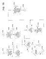
- FIGS. 7A and 7B illustrate flow charts describing operation of systems and methods according to one example of the present invention.
- FIGS. 8A and 8B illustrate flow charts describing operation of systems and methods according to another example of the present invention.
- FIGS. 9A and 9B illustrate flow charts describing operation of systems and methods according to another example of the present invention.
- examples of the present invention relate to flexible and efficient systems and methods for organizing, analyzing, and processing digital ink, e.g., in a pen-based computing system.
- the invention also relates to computer-readable media that contain computer-implementable instructions for operating systems and/or performing methods according to the invention. The following describes various examples of the invention in more detail.
- FIGS. 3 , 4 , and 5 These schematic illustrations are intended to generally illustrate both systems and methods useful in accordance with the invention. Therefore, in some instances, depending on the context of the sentence, a specific element from these figures (such as layout analysis element 302 , temporal line grouping element 408 , and the like) may be referred to as a system (e.g., a temporal line grouping system 408 ), while in other instances that same element and reference number may be used in reference to a method, a procedure, a step, a parse engine, and/or the like. All of these variations (e.g., systems, methods, steps, procedures, parse engines, and the like) are intended to be included within the scope of these figures.
- the following description is divided into sub-sections to assist the reader.
- the sub-sections include: Terms, General-Purpose Computer, Description of Examples of Systems and Methods According to the Invention, and Conclusion.
- Ink also called “digital ink” or “electronic ink”—A sequence or set of handwritten strokes.
- a sequence of strokes may include strokes in an ordered form. The sequence may be ordered in any suitable manner, such as by the time the stroke was captured and/or by where the stroke appears on a page. Other orders are possible.
- Point Information defining a location in space.
- a point may be defined relative to a capturing space (for example, points on a digitizer) and/or a display space (the points or pixels of a display device).
- Points may be represented using a variety of known techniques including two dimensional Cartesian coordinates (X, Y), polar coordinates (r, ⁇ ), three dimensional coordinates ((X, Y, Z), (r, ⁇ , ⁇ ), (X, Y, t (where t is time)), (r, ⁇ , t)), four dimensional coordinates ((X, Y, Z, t) and (r, ⁇ , ⁇ , t)), and other techniques as known in the art.
- Stroke A sequence or set of captured points.
- a stroke may be determined in a number of ways, for example, using time (e.g., a stroke is all points encountered by the stylus during a predetermined time interval), using a predetermined number of points (e.g., a stroke is all points 1 through X where X is predefined), or using stylus contact with the digitizer surface (e.g., a stroke is all points encountered by the stylus between a pen-down event and a pen-up event).
- the sequence of points may be connected with lines.
- a stroke may be represented as a point and a vector in the direction of the next point.
- a stroke may be referred to as a simple list (or array or table) of points.
- a stroke is intended to encompass any representation of points or segments relating to ink, irrespective of the underlying representation of points and/or what connects the points.
- Render The process of determining how graphics (and/or ink) are to be displayed, whether on a screen or printed.
- Parse Tree A data structure representing the structure of a document.
- FIGS. 6A and 6B illustrate examples of parse trees, both before and after a layout analysis procedure, wherein a given page of a document is parsed into blocks, lines, words, and individual strokes.
- Parse engine A single processing step or procedure in an ink analysis engine.
- a typical ink analysis engine contains several parse engines, each focusing on a particular task.
- One example of an ink analysis engine is the layout analysis engine described herein, which includes individual parse engines for temporal line grouping, spatial block grouping, spatial line grouping, list detection, and spatial word grouping.
- a parse engine takes a parse tree data structure as input and modifies it (if appropriate) to produce a parse tree with a different data structure, which in turn may be passed along as input to the next parse engine.
- FIG. 1 illustrates a schematic diagram of an exemplary conventional general-purpose digital computing environment that may be used to implement various aspects of the present invention.
- a computer 100 includes a processing unit 110 , a system memory 120 , and a system bus 130 that couples various system components including the system memory to the processing unit 110 .
- the system bus 130 may be any of several types of bus structures including a memory bus or memory controller, a peripheral bus, and a local bus using any of a variety of bus architectures.
- the system memory 120 includes read only memory (ROM) 140 and random access memory (RAM) 150 .
- a basic input/output system 160 (BIOS), containing the basic routines that help to transfer information between elements within the computer 100 , such as during start-up, is stored in the ROM 140 .
- the computer 100 also includes a hard disk drive 170 for reading from and writing to a hard disk (not shown), a magnetic disk drive 180 for reading from or writing to a removable magnetic disk 190 , and an optical disk drive 191 for reading from or writing to a removable optical disk 199 , such as a CD ROM or other optical media.
- the hard disk drive 170 , magnetic disk drive 180 , and optical disk drive 191 are connected to the system bus 130 by a hard disk drive interface 192 , a magnetic disk drive interface 193 , and an optical disk drive interface 194 , respectively.
- the drives and their associated computer-readable media provide nonvolatile storage of computer readable instructions, data structures, program modules, and other data for the personal computer 100 . It will be appreciated by those skilled in the art that other types of computer readable media that may store data that is accessible by a computer, such as magnetic cassettes, flash memory cards, digital video disks, Bernoulli cartridges, random access memories (RAMs), read only memories (ROMs), and the like, may also be used in the example operating environment.
- RAMs random access memories
- ROMs read only memories
- a number of program modules may be stored on the hard disk drive 170 , magnetic disk 190 , optical disk 199 , ROM 140 , or RAM 150 , including an operating system 195 , one or more application programs 196 , other program modules 197 , and program data 198 .
- a user may enter commands and information into the computer 100 through input devices, such as a keyboard 101 and a pointing device 102 .
- Other input devices may include a microphone, joystick, game pad, satellite dish, scanner, or the like.
- These and other input devices often are connected to the processing unit 110 through a serial port interface 106 that is coupled to the system bus 130 , but may be connected by other interfaces, such as a parallel port, game port, or a universal serial bus (USB).
- USB universal serial bus
- these devices may be coupled directly to the system bus 130 via an appropriate interface (not shown).
- a monitor 107 or other type of display device is also connected to the system bus 130 via an interface, such as a video adapter 108 .
- personal computers typically include other peripheral output devices (not shown), such as speakers and printers.
- a pen digitizer 165 and accompanying pen or user input device 166 are provided in order to digitally capture freehand input.
- the pen digitizer 165 may be coupled to the processing unit 110 via the serial port interface 106 and the system bus 130 , as shown in FIG. 1 , or through any other suitable connection.
- the digitizer 165 is shown apart from the monitor 107 , the usable input area of the digitizer 165 may be co-extensive with the display area of the monitor 107 . Further still, the digitizer 165 may be integrated in the monitor 107 , or may exist as a separate device overlaying or otherwise appended to the monitor 107 .
- the computer 100 may operate in a networked environment using logical connections to one or more remote computers, such as a remote computer 109 .
- the remote computer 109 may be a server, a router, a network PC, a peer device, or other common network node, and typically includes many or all of the elements described above relative to the computer 100 , although only a memory storage device 111 with related applications programs 196 have been illustrated in FIG. 1 .
- the logical connections depicted in FIG. 1 include a local area network (LAN) 112 and a wide area network (WAN) 113 .
- LAN local area network
- WAN wide area network
- the computer 100 When used in a LAN networking environment, the computer 100 is connected to the local network 112 through a network interface or adapter 114 .
- the personal computer 100 When used in a WAN networking environment, the personal computer 100 typically includes a modem 115 or other means for establishing a communications link over the wide area network 113 , e.g., to the Internet.
- the modem 115 which may be internal or external, is connected to the system bus 130 via the serial port interface 106 .
- program modules depicted relative to the personal computer 100 may be stored in a remote memory storage device.
- network connections shown are exemplary and other techniques for establishing a communications link between the computers may be used.
- the existence of any of various well-known protocols such as TCP/IP, Ethernet, FTP, HTTP and the like is presumed, and the system may be operated in a client-server configuration to permit a user to retrieve web pages from a web-based server.
- Any of various conventional web browsers may be used to display and manipulate data on web pages.
- FIG. 2 illustrates an exemplary pen-based computing system 201 that may be used in accordance with various aspects of the present invention. Any or all of the features, subsystems, and functions in the system of FIG. 1 may be included in the computer of FIG. 2 .
- Pen-based computing system 201 includes a large display surface 202 , e.g., a digitizing flat panel display, such as a liquid crystal display (LCD) screen, on which a plurality of windows 203 is displayed.
- a user may select, highlight, and/or write on the digitizing display surface 202 .
- suitable digitizing display surfaces 202 include electromagnetic pen digitizers, such as Mutoh or Wacom pen digitizers.
- Pen-based computing system 201 interprets gestures made using stylus 204 in order to manipulate data, enter text, create drawings, and/or execute conventional computer application tasks, such as spreadsheets, word processing programs, and the like.
- the stylus 204 may be equipped with one or more buttons or other features to augment its selection capabilities.
- the stylus 204 may be implemented as a “pencil” or “pen,” in which one end constitutes a writing element and the other end constitutes an “eraser” end, and which, when moved across the display, indicates portions of the display to be erased.
- Other types of input devices such as a mouse, trackball, or the like also may be used.
- a user's own finger may be the stylus 204 and used for selecting or indicating portions of the displayed image on a touch-sensitive or proximity-sensitive display.
- Region 205 shows a feedback region or contact region permitting the user to determine where the stylus 204 contacted the display surface 202 .
- Systems and methods according to the invention may relate to an overall electronic ink processing system or method. Various examples of the invention are described in more detail below.
- FIG. 3 is a flow diagram that illustrates an example of an overall system and method in which the incremental ink analysis systems and methods according to some examples of this invention may be used.
- incoming or input strokes 300 first are subjected to a layout analysis procedure 302 , which combines and parses the individual input strokes 300 into associated stroke sets, such as words, lines, blocks, and/or other groupings 304 .
- the layout analysis method or engine 302 ascertains certain information relating to the layout of ink strokes 300 on a page.
- the data may be introduced into a variety of additional ink analysis engines.
- the data is next introduced to a classification analysis system or engine 306 .
- the classification analysis system or engine 306 determines the type(s) of strokes included in the specific input data (e.g., whether individual strokes or stroke sets represent flow diagrams, freeform drawings, text, music, mathematics, charts, graphs, etc.).
- a user may “inform” the system as to the type of input strokes, e.g., by selecting a “drawing mode,” a “text mode,” or the like.
- Further processing of the input ink may depend on the stroke type recognized by the classification analysis system or engine 306 (or otherwise determined). For example, for strokes or stroke sets that are classified as textual writing, the classified stroke sets may be sent to a handwriting recognition system 310 or another appropriate processing system. If necessary or desired, prior to introduction into the handwriting recognition system 310 or other processing system, the input ink data may be “normalized” using a normalization algorithm or system 308 , to place the input ink data in an optimum orientation for analysis by the handwriting recognition system 310 or other processing system (e.g., to rotate the text to a horizontal base line, if necessary). Conventional normalization systems or methods 308 and/or handwriting recognition systems or methods 310 may be used without departing from the invention.
- the data output from the handwriting recognition system or method 310 may constitute or link to machine-generated text (e.g., lines, words, paragraphs, etc.) usable in any conventional manner, such as in conventional word processing systems (e.g., Microsoft WORD® or the like), e-mail handling systems, etc.
- machine-generated text e.g., lines, words, paragraphs, etc.
- the classification analysis engine 306 recognizes the input strokes or stroke sets as containing drawing strokes
- the data may then be transferred to an annotation recognition system or method 314 , which can be used to recognize textual information in the drawing.
- Further processing can proceed in any conventional manner.
- the drawings may be “cleaned-up,” wherein the handwritten annotations may be replaced with machine-generated text, handwritten drawing lines or shapes (e.g., circles, triangles, rectangles, etc.) may be replaced with machine-generated elements, and the like.
- the drawings can be introduced into any suitable programs or systems without departing from this invention.
- classification analysis systems and methods 306 used in some examples of the invention also may recognize other specific writing or drawing types without departing from the invention.
- a classification analysis system may recognize input stroke sets as containing music, mathematical information, tables, charts, graphs, flow diagrams, etc., without departing from the invention. Such stroke sets, if present, could be sent to more specialized recognition systems and/or to other suitable processing applications without departing from the invention.
- Some or all of the functions described in conjunction with FIG. 3 could be performed on input ink data after a user completely enters all ink onto the page (e.g. upon a user's command, such as a “save,” “parse,” “close,” or “recognize” command). Because of the extended computer processing time required to perform typical layout analyses and handwriting recognition analyses, however, a user may experience significant delays if processing were conducted on this infrequent ad hoc basis. These delays may last long enough such that the user would become frustrated waiting for the computer system to complete its analyses before moving on to the next desired operations (e.g., entering more ink, moving on to a new page, printing, etc.).
- Systems and methods according to examples of the present invention allow a pen-based computing system to perform various analyses, such as layout analysis 302 , classification analysis 306 , handwriting recognition analysis 310 , etc., incrementally, in real time, while the user continues to use the pen-based computing system (e.g., to enter and/or modify the ink strokes on the page).
- the various parser engines operate in a background thread, on a “snapshot” of the application data structure, in order to minimize the time that the application data structure is unavailable to the user for entering ink (the term “application data structure,” as used herein, means a data structure used in connection with an application program).
- a method includes obtaining data representing one or more ink strokes, wherein the data is stored as an application data structure, and wherein a user may change the application data structure by adding one or more ink strokes, by deleting one or more ink strokes, or by modifying one or more ink strokes.
- a first analysis procedure (such as an ink layout analysis procedure 302 ) may be conducted on a first snapshot of the application data structure to produce a first data structure, wherein the first snapshot represents the application data structure at a first point in time.
- a second analysis procedure different from the first analysis procedure may be conducted on a second snapshot of the application data structure to produce a second data structure, wherein the second snapshot represents the application data structure at a second point in time.
- This second point in time may be the same as or different from the first point in time.
- the application data structure is modified based on these first and second analysis procedures.
- input ink data changing the application data structure may be received after the first point in time and/or after the second point in time (when the snapshot(s) is (are) taken), but before the modifying step is carried out.
- the application data structure will not be modified to over-write changes made by the user after the first (or second) point in time (i.e., the user-made changes to the application data structure will take precedence over changes to the application data structure made based on the analysis procedures).
- a “snapshot,” as used in this specification, refers to a copy of the data structure of the input ink data at a specific point in time.
- analyses by separate analysis engines may proceed concurrently, partially concurrently, consecutively, or in any desired order without departing from the invention.
- the analysis engines may operate on the snapshots while the application data structure remains available to the user for ink entry and/or editing and/or other suitable operations.
- Another example of the invention relates to a different method for processing digital ink.
- data representing one or more digital ink strokes is received and stored as an application data structure.
- a first snapshot of the application data structure is analyzed to produce a first data structure (which is a revised version of the application data structure).
- the application data structure is modified (e.g., through user input, in which a user adds one or more ink strokes, deletes one or more ink strokes, or otherwise modifies one or more ink strokes).
- a revised application data structure based on the first data structure and modifications to the application data structure made during the modifying step, is created and replaces the original application data structure.
- the analysis step may include two or more analysis procedures without departing from the invention, and these analysis procedures may take place concurrently, partially concurrently, consecutively, or in any other suitable manner known in the art.
- Another example of a method for processing digital ink includes receiving data representing one or more digital ink strokes over a first time period, wherein the data is stored as an application data structure.
- This application data structure is subjected to plural analyses over the first time period, wherein, during at least one of the analyzing steps, a user makes changes to the application data structure (e.g., by adding one or more ink strokes, deleting one or more ink strokes, or modifying one or more ink strokes).
- the user's changes to the application data structure do not affect the data structure being analyzed in the analyzing step.
- the application data structure is modified to form a revised application data structure, wherein the revised application data structure is produced taking into consideration the modifications made to the data structure during the analyzing step(s) and any changes made by the user during the analyzing step(s).
- the analyzing step(s) in this example may include two or more different analyzing procedures (such as a layout analysis procedure and a handwriting recognition analysis procedure), and the analyzing procedures may take place concurrently, partially concurrently, consecutively, or in any other suitable manner, without departing from the invention.
- the revised or modified application data structure in these examples may contain changes made by the user and/or the system during the analyzing step(s).
- user-made changes will take precedence over system-made changes, if there is overlap or conflict.
- the analysis and modifying steps may be confined to portions of the application data structure changed since the previous processing steps, and to area in the data structure immediately adjacent the portions of the data structure changed since the previous processing steps.
- the systems according to the invention may include various components, such as an input device for receiving input ink data and a processor system for processing the data, like the systems described above in conjunction with FIGS. 1 and 2 .
- FIG. 4 illustrates a schematic diagram of one example of a system useful for practicing the present invention.
- the overall system 1310 includes an application system or program 1320 , which includes a parser 1322 .
- the overall system 1310 may be embodied in a pen-based computing system like that illustrated in FIG. 2 .
- the user 1300 enters ink strokes into the system 1310 (or the ink strokes are downloaded, e.g., from memory or an external source), and the ink strokes are stored by the application program 1320 , for example, in an application data structure 1302 (which may be in the form of a document tree data structure 1302 , like those illustrated in FIGS. 6A and 6B ).
- the parser 1322 contains a mirror tree data structure 1304 .
- Changes made to the document tree data structure 1302 e.g., by the user 1300 , the parser 1322 , from another source, etc.
- the mirror tree data structure 1304 generally “mirrors” the content of the document tree data structure 1302 .
- the mirror tree data structure 1304 is used to supply input data to the two analysis engines 1306 and 1308 in the parser 1322 .
- one analysis engine is a layout analysis engine 1306 (which may conduct, for example, a layout analysis 302 , as discussed above in conjunction with FIG. 3 ), and the other is a recognition engine 1308 (which may conduct, for example, handwriting recognition analysis 310 and/or annotation recognition analysis 314 , as discussed above in conjunction with FIG. 3 ).
- the engines 1306 and 1308 receive “snapshots” 1324 and 1326 , respectively, of the mirror tree data structure 1304 as input data, and they operate on these “snapshots” 1324 and 1326 instead of operating directly on the document tree data structure 1302 or the mirror tree data structure 1304 .
- the user 1300 can continue performing operations on the document tree data structure 1302 in the application program 1320 while the various parser analysis engines 1306 and 1308 also are operating, and the user 1300 does not experience an interruption in operation (e.g., processing delays) as the engines 1306 and 1308 operate on the data.
- an existing snapshot data structure is compared with the mirror tree data structure 1304 .
- the differences between the two are noted, and a minimal number of operations are performed to synchronize the snapshot to the mirror tree data structure 1304 .
- minimal data rewrite occurs in making the snapshot (e.g., unchanged data from a previous snapshot is not rewritten).
- the output of the parser engines 1306 and 1308 may be a modified or revised data structure.
- the output of layout analysis engine 1306 may be a data structure that includes individual ink strokes grouped into associated words, lines, blocks, and the like. Operation of a layout analysis engine of this type is described in more detail below.
- the parser engine 1308 is a handwriting recognition system 310
- the output may include information or a data structure that ties the ink strokes to machine-generated text.
- the parser engines 1306 and 1308 complete their operations on the snapshot input data 1324 and 1326 , respectively, the resulting information is sent back to the application program 1320 , as indicated by arrows 1328 and 1330 , respectively.
- the user 1300 may change the document tree data structure 1302 during the time period that the parser engines 1306 and 1308 operate on the snapshots 1324 and 1326 . Therefore, before writing the parser analysis engine results back to the document tree data structure 1302 , the parser 1322 compares the document tree data structure 1302 currently in the application program 1320 (including the user's changes) to the revised document tree data structure(s) sent by the parser engines 1306 and 1308 , optionally using the mirror tree data structure 1304 .
- the application document tree data structure 1302 is revised only to include the changes made by the parser analysis engines that do not conflict with the user-made changes (user-made changes override parser-made changes).
- the finally revised document tree data structure present in the application program 1320 will include all changes made by the user 1300 and the results of the previous parser engine analyses, to the extent that the parser engine made changes that are not inconsistent with or trumped by user made changes.
- the document tree data structure 1302 contains shared data ultimately modifiable by the user 1300 as well as the parser engines 1306 and 1308 , the user 1300 cannot input new data into the document tree data structure 1302 while it is being rewritten to include the parser-made changes. If a user 1300 attempts to do so, systems and methods according to the invention can handle these efforts in any suitable manner. For example the new strokes or changes may be ignored, or they may be stored in a temporary buffer memory until the revised application document tree data structure is available for data input.
- the document tree data structure 1302 in the application program 1320 generally is unavailable only during the time the system rewrites the changed portions of the data structure, the unavailable time period typically is quite short, and often unnoticed by the user.
- the mirror tree data structure 1304 is updated to mirror the rewritten or modified document tree data structure 1302 , and the parser engines 1306 and 1308 can repeat their analyses (if necessary).
- the parser engines 1306 and 1308 will operate only on the portions of the document tree data structure that have been recently modified (and any portions affected by the recent modifications), to reduce processing time.
- the parser 1322 can generally keep up with the user's data entry, thereby minimizing processing delays observed by the user.
- processing time may be reduced by limiting processing to portions of the data structure where changes have occurred (and all areas affected by these changes). If user input or previous parser engine operations have not affected some portions of a data structure, there may be no need for the parser engine(s) to again analyze these same portions.
- systems and methods according to some examples may reanalyze any portion of the data structure located within a predetermined distance of a change. For example, reanalysis may include the line of any change and any one or two lines surrounding the change, any strokes located within a circle of a preselected radius surrounding the change, any block of text (as described in more detail below) including a change, or the like. The following explains examples of the invention that take advantage of these features in more detail.
- the data analyzed or processed in systems and methods according to examples of the present invention can take on any suitable form or structure.
- individual strokes 300 of input ink data are combined together into a data structure as a result of a succession of decisions made by a layout analysis engine 302 , which groups or associates certain individual strokes based on an overall ink layout and statistics obtained from the input ink.
- the layout analysis engine 302 may provide a hierarchical clustering of ink strokes on a page, which allows global statistic calculations over the cluster(s).
- the first stroke grouping decisions are conservative, based on local layout relationships when the clusters of ink strokes are small (e.g., clusters representing individual strokes or relatively short combinations of strokes).
- Later stroke grouping decisions can be more aggressive, due to the more global statistics collected from larger clusters (e.g., stroke sizes over a longer line, relative stroke spacing, line angles, etc.). Multiple passes through the input ink data may be conducted to enable increasingly aggressive decision making in determining whether to merge strokes to form stroke sets, such as words, lines, and/or blocks 304 of input ink strokes.
- FIG. 5 generally illustrates steps or parse engines involved in one example of an ink layout analysis parser engine, system, or method 1306 useful in producing and/or modifying data structures used in some examples of this invention. Because of the freedom provided to a user in inputting digital ink into the systems and methods according to some examples of the invention (e.g., a user is allowed to write anywhere on a page, in any orientation, at any time, using any desired stroke size), when the layout analysis procedure 302 of FIG. 5 begins, there may be no preliminary information from which to determine the proper layout, orientation, or type of input data (e.g., whether the incoming input data 400 is textual, drawing, mathematic, music, flow diagrams, charts, graphs, etc.). Element 402 in FIG.
- the layout analysis procedure 302 treats every stroke S 500 on a given page P 508 as a separate word W 502 , every word W 502 is treated as a separate line L 504 , and every line L 504 is treated as a separate block B 506 .
- the layout analysis engine 302 performs the task of associating or merging strokes together to form stroke sets containing proper words, lines, and blocks of associated ink data. While any suitable layout analysis engine could be used in conjunction with this invention, one example is described in more detail below.
- the layout analysis engine 302 operates greedily, such that during each pass (or operation of each parse engine), stroke or line merger operations occur, but splits do not. Moreover, the engine 302 may be operated with tests and tolerances such that it should not be necessary to go back and correct an undesired merger operation.
- FIG. 6B illustrates a graphical representation 406 of a possible data structure for the data output 404 from the layout analysis engine 302 .
- the Page 508 overall contains the same stroke information, but certain strokes S 500 have been combined or associated together to form words W 510 , and certain words W 510 have been joined together to form a line L 512 in the data structure of FIG. 6B .
- a word W 510 may contain any number of strokes S 500
- likewise a line L 512 may contain any number of words W 510 .
- two or more lines L 512 also may be joined together to form a block B 514 .
- each line level node may store a regression/fit line of all points that make up the strokes of the line, the convex hull of each stroke in the line, and/or any other desired information.
- the parse tree data structures can be modified by applying various elementary operations on the strokes, words, lines, and blocks contained in it. Suitable operations may include: add, remove, merge, split, and reparent. More complex operations may be composed using these elementary operations. As these operations are performed on the data structure tree, the statistics maintained at the different node levels may be automatically updated to correspond to the new structure.
- FIG. 5 provides a schematic overview of one example of a suitable layout analysis engine 1306 useful in some examples of this present invention.
- a first step in the layout analysis procedure 302 is a temporal line grouping step 408 , which generally compares features of temporally adjacent strokes and combines them as lines, if appropriate. Various factors may be taken into account in determining whether a temporal line grouping should be made from two or more strokes, such as stroke size, inter-stroke spacing, stroke angle, etc.
- a spatial block grouping step 410 compares the temporal line groupings and combines lines that are located close to one another as spatial blocks. Various factors may be taken into account in determining whether a spatial block grouping should be made, such as stroke size, inter-stroke spacing, line angle, etc.
- the temporally grouped lines may be further grouped, optionally taking into consideration their spatial block relationship or orientation, in a spatial line grouping step 412 .
- This spatial line grouping step 412 need not consider the time of one stroke compared to another stroke, although factors in addition to the lines' spatial relationship may be taken into consideration, such as line angle, stroke size, etc.
- the results of the spatial block grouping procedure 410 described above may be used as a factor in determining whether a spatial line grouping should be made between two existing temporal line groupings.
- the layout analysis procedure 302 may then combine the individual strokes in the line groupings into one or more spatial word groupings 416 , depending, for example, on factors such as inter-stroke spacing, line orientation, stroke size, etc.
- FIG. 5 also illustrates an optional parse engine or step in broken lines that may be performed as part of a layout analysis 302 .
- This optional step is called “list detection” 414 .
- list detection Often, when people write a list, they tend to write a column of numbers or letters, and then fill in the list elements. At other times, people will write out the content of the list, and then later add a column of numbers, letters, or bullet points.
- This list detection engine 414 may detect these special circumstances and combines the number, letter, or bullet point strokes with the corresponding list element text.
- the various steps in this exemplary ink analysis engine 302 may be changed in order or omitted without departing from the invention.
- the spatial line grouping step 412 may take place before the spatial block grouping step 410 .
- the output data 404 from the layout analysis engine 302 can be used in any suitable manner, such as in a classification engine 306 , as illustrated in FIG. 3 , and from there the data may proceed to other appropriate processing engines (e.g., annotation recognition 314 , handwriting recognition 310 , etc.).
- Layout analysis engine 302 or a combination of layout analysis engine 302 and classification engine 306 , may form a parser engine 1306 as illustrated in conjunction with FIG. 4 .
- this invention is not limited to operation with a layout analysis engine or any specific type of analysis engine.
- Other suitable engines or procedures for grouping or associating individual strokes into appropriate data structures or any other desired analysis can be performed without departing from this invention.
- the user could indicate to the system that certain strokes always should be grouped together (e.g., by drawing a line around, highlighting, or otherwise selecting input data strokes to be associated together).
- the incremental analysis systems and methods according to the invention may include any suitable data processing analyses, like those illustrated in conjunction with FIG. 3 .
- the described examples of the invention include a layout analysis 302 , which also may include a classification analysis 306 , and a handwriting recognition analysis 310 .
- the layout analysis process (e.g., like that illustrated in FIG. 5 ) or other desired analysis procedures may initially begin at any time after the user begins adding strokes to a page and/or editing strokes on a page and/or otherwise modifying strokes on a page. As the user continues modifying the page, the layout analysis process 302 (and/or other desired procedures) may be repeated on the revised page data structure, optionally focusing on portions of the data structure that have been modified since a previous iteration of the layout analysis engine 302 (and portions surrounding or affected by the changed portions).
- FIGS. 7A , 7 B, 8 A, 8 B, 9 A, and 9 B illustrate flow diagrams of various procedures for incrementally analyzing input data.
- FIGS. 7A and 7B illustrate an exemplary incremental ink analysis procedure in which two different parser engines (e.g., a layout analysis engine and a handwriting recognition engine) operate concurrently and in parallel.
- the system receives initial user input strokes as input data (alternatively, a user could download a starting document from another source or another application, or otherwise receive a suitable input or starting document).
- the input data may be contained in a document tree data structure in which every stroke is treated as a separate word, a separate line, and a separate block.
- a layout analysis engine like that illustrated in FIG. 5
- One purpose of a layout analysis engine is to group the individual strokes into associated words, lines, and blocks of ink data.
- Step S 702 the mirror tree data structure 1304 in the parser engine 1322 is set equal to the document tree data structure 1302 being used in the application program 1320 .
- the systems and methods according to this example of the invention keep track of the changes made by the user by marking the nodes (see FIGS. 6A and 6B ) that have been changed by the user as “user dirty” (when the user has changed or added a stroke, word, line, or block) or “delete dirty” (when the user has deleted a stroke, word, line, or block).
- Step S 704 the system determines whether any user dirty or delete dirty nodes exist in the data structure.
- Step S 706 a snapshot 1324 is taken of the mirror tree data structure 1304 (Step S 706 ), and the layout analysis engine 1306 operates on this snapshot 1324 (Step S 708 ).
- Step S 704 the user dirty and/or delete dirty nodes in the mirror tree are changed to “clean.”
- Processing may take place on any suitable amount of data surrounding each dirty node (e.g., all data in the block containing the dirty node; all data within a predetermined distance of the dirty node; all data in the line containing the dirty node and, optionally, all data in one or more lines surrounding the dirty node (if any); etc.).
- data surrounding each dirty node e.g., all data in the block containing the dirty node; all data within a predetermined distance of the dirty node; all data in the line containing the dirty node and, optionally, all data in one or more lines surrounding the dirty node (if any); etc.
- the systems and methods according to at least some examples of the invention will minimize or reduce redundant calculations (e.g., by not reanalyzing unchanged nodes) while still reanalyzing sufficient surrounding data to assure that all necessary data is reanalyzed and accuracy is maintained.
- Step S 712 nodes that are changed by the layout analysis engine 1306 are marked as “parser dirty” (Step S 712 ), so that the systems and methods according to this example of the invention can keep track of previous changes to the data structure made by the layout analysis engine 1306 .
- the systems and methods according to this example of the invention may wait to synchronize the timing with the recognition engine (Step S 714 ), which is explained in more detail below. Because Step S 714 is optional and/or not always necessary, it is shown in broken lines in FIG. 7B .
- Step S 704 If, at Step S 704 , there are no user or delete dirty nodes (answer NO), the procedure skips Steps S 706 , S 708 , and S 712 and moves forward to Step S 714 , as indicated by transfer bullet D (Step S 716 ).
- the systems and methods according to the example of the invention illustrated in FIGS. 7A and 7B include two independent analysis engines or threads, namely the layout analysis engine or thread 1306 and the recognition engine or thread 1308 , running concurrently and in parallel. Of course, any number of independent engines or threads may run in the background of the application program 1320 without departing from the invention.
- Step S 702 the systems and methods according to this example of the invention determine whether the mirror tree data structure contains any new parser dirty nodes (Step S 718 ). If YES, a snapshot 1326 of the mirror tree data structure 1304 is taken (Step S 720 ), and the recognition engine 1308 operates on this snapshot 1326 (Step S 722 ).
- the snapshot 1326 used in Step S 722 may be the same as snapshot 1324 used in Step S 708 (e.g., only one “snapshot” is taken) or it may be different (indicating that the snapshots were taken at different points in time), without departing from the invention.
- the parser dirty nodes are marked “clean” in the mirror tree.
- Step S 724 in the next step of the illustrated procedure, the system marks any nodes changed by the recognition engine as “reco dirty” (Step S 726 ). Then, in Step S 728 , processing in the recognition engine 1308 waits (if necessary) to synchronize with the layout analysis engine 1306 . Again, because Step S 728 is optional and/or not always necessary, it is shown in broken lines.
- Step S 718 the procedure determines that the mirror tree data structure 1304 does not include parser dirty nodes (answer NO)
- the procedure skips Steps S 720 , S 722 , and S 726 and jumps to Step S 728 , as indicated by transfer bullet E (Step S 730 ).
- Step S 732 determines whether the snapshots have been changed by the layout analysis engine 1306 and/or the handwriting recognition engine 1308 (Step S 732 ). If there are no snapshot changes (answer YES at Step S 732 ), the system determines whether processing has been completed (Step S 734 ), and if YES, the procedure ends (Step S 736 ). This ending may be temporary, for example, lasting only until a user resumes making changes to the document tree data structure 1302 . As another alternative, the system may check automatically and periodically for new user-made changes. If processing is not completed at Step S 734 (answer NO, for example, if a user has made changes to the document tree data structure), the procedure returns to Step S 702 , as indicated by transfer bullet A (Step S 738 ).
- Step S 732 the system determines that at least one snapshot has been changed (Answer NO)
- the system determines whether both parser engines made changes to their respective snapshot (Step S 740 ). If both parser engines did make changes to their snapshot (answer YES), the system then combines the layout analysis and handwriting recognition changed snapshots into one composite changed data structure (Step S 742 ). If there is overlap or conflict, parser dirty nodes will override reco dirty nodes in this example because, as compared to the reco dirty nodes, the parser dirty nodes have more recently been changed by the user.
- Step S 742 is skipped, and the system proceeds using the single changed snapshot.
- Step S 744 the parser 1322 uses the information contained in the snapshot data structure to rewrite the data in the document tree data structure 1302 . Only portions of the document tree data structure 1302 that were changed by the layout analysis engine or the recognition engine are rewritten. In this manner, the processing system does not take time rewriting data in the document tree data structure 1302 that was not changed. Also, if user-made changes to the document tree data structure 1302 overlap or conflict with layout analysis engine or recognition engine made changes in the data structure, the document tree data structure 1302 is not changed to include the conflicting layout analysis engine or recognition engine made changes. In this way, the user-made changes take precedence over the system-made changes. The determination as to whether the document tree data structure 1302 contains new user-made changes may be accomplished, for example, by looking for user or delete dirty nodes in the mirror tree data structure 1304 .
- Step S 738 the procedure then returns to Step S 702 to repeat the process on the revised or modified document tree data structure.
- FIGS. 8A and 8B illustrate another example of a flow diagram that may be used in practicing the incremental analysis procedure according to the present invention.
- the two parser engines 1306 and 1308 run consecutively, with the layout analysis engine 1306 running first and the handwriting recognition engine 1308 running later.
- Step S 800 the initial user input strokes are received in the document tree data structure 1302 (Step S 800 ) (or the data is introduced into the system in some other manner, e.g., by downloading, from memory, from another application, etc.). Again, as this occurs, the mirror tree data structure 1304 is revised to mirror the document tree data structure 1302 (Step S 802 ). In the next step, the system determines whether there are any user or delete dirty nodes in the mirror tree data structure 1304 (Step S 804 ). If YES, a snapshot of the mirror tree data structure is taken (Step S 806 ), and the layout analysis engine 1306 operates on the snapshot (Step S 808 ).
- Step S 810 If the answer is NO at Step S 804 , the procedure skips Steps S 806 , S 808 , and S 810 .
- Step S 812 the system determines whether there are any parser dirty nodes in the snapshot 1324 (if one has already been taken) or in the mirror tree data structure 1304 (if no snapshot has been taken). If parser dirty nodes exist (answer YES), then a snapshot is taken if one has not previously been taken (Step S 814 ), and then the handwriting recognition engine 1308 is run on the snapshot (Step S 816 ). Once a snapshot is taken here (if necessary), any parser dirty nodes in the mirror tree data structure 1304 are marked “clean.” Any nodes changed in the snapshot during operation of the handwriting recognition engine 1308 are marked “reco dirty” (Step S 818 ). Alternatively, a single snapshot may be taken at the beginning of the procedure of FIG. 8A (before operation of the parse engine), and then all nodes of the mirror tree 1304 can be marked clean after the snapshot is taken.
- the parser 1322 uses the information contained in the snapshot data structure to rewrite the data in the document tree data structure 1302 (Step S 822 ). Only portions of the document tree data structure that were changed by the layout analysis engine or the recognition engine are rewritten, to thereby reduce data writing time (no need to rewrite unchanged data). Also, as described above, user-made changes to the document tree data structure 1302 will take precedence in the event that the user-made changes overlap or conflict with the layout analysis engine or recognition engine made changes.
- Step S 828 determines whether processing has been completed. If YES, the procedure ends (Step S 830 , at least temporarily, until more changes are made to the document tree data structure), and if NO, the procedure returns to Step S 802 and repeats, as indicated by transfer bullet A (Step S 832 ). Also, as noted above, the system may periodically and automatically check for new user input.
- Step S 812 If no parser dirty nodes exist at Step S 812 (Answer NO), the procedure skips forward to Step S 828 , as indicated by transfer bullet C, Step S 834 .
- FIGS. 9A and 9B illustrate an example of the invention in which the layout analysis engine 1306 and the handwriting recognition engine 1308 operate independent of one another, optionally in parallel and concurrently.
- FIG. 9A illustrates operation of the layout analysis engine 1306 .
- the system receives initial input in any appropriate manner (e.g., strokes from a user, download from some other source or application, etc.), and the mirror tree data structure 1304 is maintained equivalent to the document tree data structure 1302 on which the user operates (Step S 902 ).
- the system determines whether the mirror tree data structure 1304 contains user dirty or delete dirty nodes (Step S 904 ).
- Step S 906 a snapshot 1324 of the mirror tree data structure 1304 is taken (Step S 906 ), and the layout analysis engine runs on the snapshot 1324 (Step S 908 ).
- the mirror tree is changed to mark the user and/or delete dirty nodes as “clean.”
- any nodes in the snapshot 1324 changed by the layout analysis engine 1306 are marked “parser dirty” (Step S 910 ).
- Step S 912 the parser 1322 uses the information contained in the snapshot data structure to rewrite the data in the document tree data structure 1302 . Only portions of the document tree data structure that were changed by the layout analysis engine are rewritten, to thereby reduce data writing time (no need to rewrite unchanged data). Also, as described above, user-made changes to the document tree data structure 1302 will take precedence in the event that the user-made changes overlap or conflict with the layout analysis engine made changes.
- Step S 918 determines whether processing has been completed (Step S 918 ), and if YES, the procedure ends (Step S 920 ), at least temporarily until additional changes are introduced into the document tree data structure 1302 or until an automatic or periodic review of the system is performed, as discussed above. If additional processing is required (answer NO at Step S 918 ), the procedure returns to Step S 902 , as indicated by transfer bullet A (Step S 922 ).
- Step S 904 If, at Step S 904 , it is determined that the mirror tree data structure 1304 does not contain any user dirty or delete dirty nodes (answer NO), the procedure advances to Step S 918 , as shown by transfer bullet D (Step S 924 ).
- Step S 950 the system receives initial input in any appropriate manner (e.g., strokes from a user, or other input, as described above), and the mirror tree data structure 1304 is maintained equivalent to the document tree data structure 1302 on which the user or application program 1320 operates (Step S 952 ).
- the system determines whether the mirror tree data structure 1304 contains parser dirty nodes (Step S 954 ). If YES, a snapshot 1326 of the mirror tree data structure 1304 is taken (Step S 956 ), and the handwriting recognition engine runs on the snapshot 1326 (Step S 958 ).
- the parser dirty nodes in the mirror tree data structure 1304 are marked “clean” after the snapshot is taken. As in the previous examples, any nodes in the snapshot changed by the handwriting recognition engine may be marked “reco dirty” (Step S 960 ).
- Step S 962 the parser 1322 uses the information contained in the snapshot data structure to rewrite the data in the document tree data structure 1302 . Only portions of the document tree data structure that were changed by the recognition engine are rewritten, to thereby reduce data writing time (no need to rewrite unchanged data). Also, user-made changes to the document tree data structure 1302 and parser engine made changes to the document tree data structure 1302 since the last snapshot will take precedence in the event that either of these changes overlap or conflict with the recognition engine made changes.
- Step S 968 determines whether processing has been completed (Step S 968 ), and if YES, the procedure ends (Step S 970 ), at least temporarily until additional changes are introduced into the document tree data structure 1302 or until an automatic or periodic check for new data is performed. If additional processing is required (answer NO at Step S 968 ), the procedure returns to Step S 952 , as indicated by transfer bullet A (Step S 972 ).
- Step S 954 If at Step S 954 it is determined that the mirror tree data structure does not contain any parser dirty nodes (answer NO), the procedure advances to Step S 968 , as shown by transfer bullet D (Step S 974 ).
Landscapes
- Engineering & Computer Science (AREA)
- Computer Vision & Pattern Recognition (AREA)
- Physics & Mathematics (AREA)
- General Physics & Mathematics (AREA)
- Multimedia (AREA)
- Theoretical Computer Science (AREA)
- Character Discrimination (AREA)
- Particle Formation And Scattering Control In Inkjet Printers (AREA)
- Editing Of Facsimile Originals (AREA)
- Automatic Analysis And Handling Materials Therefor (AREA)
Priority Applications (5)
| Application Number | Priority Date | Filing Date | Title |
|---|---|---|---|
| US10/143,804 US7123770B2 (en) | 2002-05-14 | 2002-05-14 | Incremental system for real time digital ink analysis |
| EP03003753A EP1367528B1 (de) | 2002-05-14 | 2003-02-19 | Inkrementales System zur Echtzeitanalyse digitaler Tinte |
| AT03003753T ATE367619T1 (de) | 2002-05-14 | 2003-02-19 | Inkrementales system zur echtzeitanalyse digitaler tinte |
| DE60314940T DE60314940T2 (de) | 2002-05-14 | 2003-02-19 | Inkrementales System zur Echtzeitanalyse digitaler Tinte |
| US11/468,404 US7813556B2 (en) | 2002-05-14 | 2006-08-30 | Incremental system for real time digital ink analysis |
Applications Claiming Priority (1)
| Application Number | Priority Date | Filing Date | Title |
|---|---|---|---|
| US10/143,804 US7123770B2 (en) | 2002-05-14 | 2002-05-14 | Incremental system for real time digital ink analysis |
Related Child Applications (1)
| Application Number | Title | Priority Date | Filing Date |
|---|---|---|---|
| US11/468,404 Continuation US7813556B2 (en) | 2002-05-14 | 2006-08-30 | Incremental system for real time digital ink analysis |
Publications (2)
| Publication Number | Publication Date |
|---|---|
| US20030215138A1 US20030215138A1 (en) | 2003-11-20 |
| US7123770B2 true US7123770B2 (en) | 2006-10-17 |
Family
ID=29418469
Family Applications (2)
| Application Number | Title | Priority Date | Filing Date |
|---|---|---|---|
| US10/143,804 Active 2024-07-08 US7123770B2 (en) | 2002-05-14 | 2002-05-14 | Incremental system for real time digital ink analysis |
| US11/468,404 Expired - Fee Related US7813556B2 (en) | 2002-05-14 | 2006-08-30 | Incremental system for real time digital ink analysis |
Family Applications After (1)
| Application Number | Title | Priority Date | Filing Date |
|---|---|---|---|
| US11/468,404 Expired - Fee Related US7813556B2 (en) | 2002-05-14 | 2006-08-30 | Incremental system for real time digital ink analysis |
Country Status (4)
| Country | Link |
|---|---|
| US (2) | US7123770B2 (de) |
| EP (1) | EP1367528B1 (de) |
| AT (1) | ATE367619T1 (de) |
| DE (1) | DE60314940T2 (de) |
Cited By (14)
| Publication number | Priority date | Publication date | Assignee | Title |
|---|---|---|---|---|
| US20060294037A1 (en) * | 2003-08-06 | 2006-12-28 | Microsoft Corporation | Cost-benefit approach to automatically composing answers to questions by extracting information from large unstructured corpora |
| US20090002392A1 (en) * | 2007-06-26 | 2009-01-01 | Microsoft Corporation | Integrated platform for user input of digital ink |
| US20090003658A1 (en) * | 2007-06-26 | 2009-01-01 | Microsoft Corporation | Digital ink-based search |
| US20090121894A1 (en) * | 2007-11-14 | 2009-05-14 | Microsoft Corporation | Magic wand |
| US20090278799A1 (en) * | 2008-05-12 | 2009-11-12 | Microsoft Corporation | Computer vision-based multi-touch sensing using infrared lasers |
| US20100031202A1 (en) * | 2008-08-04 | 2010-02-04 | Microsoft Corporation | User-defined gesture set for surface computing |
| US8847739B2 (en) | 2008-08-04 | 2014-09-30 | Microsoft Corporation | Fusing RFID and vision for surface object tracking |
| US20150205517A1 (en) * | 2014-01-22 | 2015-07-23 | Lenovo (Singapore) Pte. Ltd. | Automatic launch and data fill of application |
| US9898841B2 (en) | 2015-06-29 | 2018-02-20 | Microsoft Technology Licensing, Llc | Synchronizing digital ink stroke rendering |
| US10146759B2 (en) | 2016-03-24 | 2018-12-04 | Microsoft Technology Licensing, Llc | Controlling digital input |
| US10162518B2 (en) | 2017-02-03 | 2018-12-25 | Microsoft Technology Licensing, Llc | Reversible digital ink for inking application user interfaces |
| US10210383B2 (en) | 2015-09-03 | 2019-02-19 | Microsoft Technology Licensing, Llc | Interacting with an assistant component based on captured stroke information |
| US10387034B2 (en) | 2015-09-03 | 2019-08-20 | Microsoft Technology Licensing, Llc | Modifying captured stroke information into an actionable form |
| US10817124B2 (en) | 2014-06-03 | 2020-10-27 | Lenovo (Singapore) Pte. Ltd. | Presenting user interface on a first device based on detection of a second device within a proximity to the first device |
Families Citing this family (18)
| Publication number | Priority date | Publication date | Assignee | Title |
|---|---|---|---|---|
| US7958132B2 (en) * | 2004-02-10 | 2011-06-07 | Microsoft Corporation | Voting based scheme for electronic document node reuse |
| US20050187741A1 (en) * | 2004-02-19 | 2005-08-25 | Microsoft Corporation | Development tool for defining attributes within a multi-dimensional space |
| US7284192B2 (en) | 2004-06-24 | 2007-10-16 | Avaya Technology Corp. | Architecture for ink annotations on web documents |
| US20060085740A1 (en) | 2004-10-20 | 2006-04-20 | Microsoft Corporation | Parsing hierarchical lists and outlines |
| US8509563B2 (en) | 2006-02-02 | 2013-08-13 | Microsoft Corporation | Generation of documents from images |
| US20080235263A1 (en) * | 2007-03-02 | 2008-09-25 | Adi, Llc | Automating Creation of Digital Test Materials |
| US7725493B2 (en) | 2007-03-23 | 2010-05-25 | Palo Alto Research Center Incorporated | Optimization method and process using tree searching operation and non-overlapping support constraint requirements |
| US8014607B2 (en) * | 2007-03-23 | 2011-09-06 | Palo Alto Research Center Incorporated | Method and apparatus for creating and editing node-link diagrams in pen computing systems |
| US7907141B2 (en) | 2007-03-23 | 2011-03-15 | Palo Alto Research Center Incorporated | Methods and processes for recognition of electronic ink strokes |
| US7945097B2 (en) * | 2007-05-21 | 2011-05-17 | Microsoft Corporation | Classifying digital ink into a writing or a drawing |
| US20090245646A1 (en) * | 2008-03-28 | 2009-10-01 | Microsoft Corporation | Online Handwriting Expression Recognition |
| US20100166314A1 (en) * | 2008-12-30 | 2010-07-01 | Microsoft Corporation | Segment Sequence-Based Handwritten Expression Recognition |
| CN103019398A (zh) * | 2011-09-20 | 2013-04-03 | 腾讯科技(深圳)有限公司 | 一种文字输入方法及文字输入装置 |
| WO2015141260A1 (ja) * | 2014-03-17 | 2015-09-24 | 株式会社河合楽器製作所 | 手書き音楽記号認識装置およびプログラム |
| US11010401B2 (en) * | 2017-04-25 | 2021-05-18 | Microsoft Technology Licensing, Llc | Efficient snapshot generation of data tables |
| US11023661B2 (en) | 2018-05-03 | 2021-06-01 | Microsoft Technology Licensing, Llc | Visually enhanced digital ink |
| US11372823B2 (en) * | 2019-02-06 | 2022-06-28 | President And Fellows Of Harvard College | File management with log-structured merge bush |
| CN111159891B (zh) * | 2019-12-27 | 2022-03-15 | 南京航空航天大学 | 基于dnn神经网络的单样本极化滤波器系数预测方法 |
Citations (1)
| Publication number | Priority date | Publication date | Assignee | Title |
|---|---|---|---|---|
| US6028959A (en) | 1996-11-15 | 2000-02-22 | Synaptics, Inc. | Incremental ideographic character input method |
-
2002
- 2002-05-14 US US10/143,804 patent/US7123770B2/en active Active
-
2003
- 2003-02-19 EP EP03003753A patent/EP1367528B1/de not_active Expired - Lifetime
- 2003-02-19 DE DE60314940T patent/DE60314940T2/de not_active Expired - Lifetime
- 2003-02-19 AT AT03003753T patent/ATE367619T1/de not_active IP Right Cessation
-
2006
- 2006-08-30 US US11/468,404 patent/US7813556B2/en not_active Expired - Fee Related
Patent Citations (1)
| Publication number | Priority date | Publication date | Assignee | Title |
|---|---|---|---|---|
| US6028959A (en) | 1996-11-15 | 2000-02-22 | Synaptics, Inc. | Incremental ideographic character input method |
Non-Patent Citations (6)
| Title |
|---|
| European Search Report dated Nov. 18, 2004. |
| Michael Shilman et al., "Statistical Visual Language Models for Ink Parsing", pp. 126-132, 2002. |
| Peter Tandler et al., "Using Incremental Gesture Recognition to Provide Immediate Feedback while Drawing Pen Gestures", 2001. |
| Rui Zhao, "Incremental Recognition in Gesture-Based and Syntax-Directed Diagram Editors", pp. 95-100, 1993 ACM. |
| Steve Smithies et al., "A Handwriting-Based Equation Editor", pp. 84-91, 1999. |
| Thomas Fontaine et al., "A Hybrid System for Handprinted Word Recognition", pp. 227-234, 1993 IEEE. |
Cited By (21)
| Publication number | Priority date | Publication date | Assignee | Title |
|---|---|---|---|---|
| US20060294037A1 (en) * | 2003-08-06 | 2006-12-28 | Microsoft Corporation | Cost-benefit approach to automatically composing answers to questions by extracting information from large unstructured corpora |
| US7516113B2 (en) * | 2003-08-06 | 2009-04-07 | Microsoft Corporation | Cost-benefit approach to automatically composing answers to questions by extracting information from large unstructured corpora |
| US20090002392A1 (en) * | 2007-06-26 | 2009-01-01 | Microsoft Corporation | Integrated platform for user input of digital ink |
| US20090003658A1 (en) * | 2007-06-26 | 2009-01-01 | Microsoft Corporation | Digital ink-based search |
| US8094939B2 (en) * | 2007-06-26 | 2012-01-10 | Microsoft Corporation | Digital ink-based search |
| US8315482B2 (en) | 2007-06-26 | 2012-11-20 | Microsoft Corporation | Integrated platform for user input of digital ink |
| US20090121894A1 (en) * | 2007-11-14 | 2009-05-14 | Microsoft Corporation | Magic wand |
| US9171454B2 (en) | 2007-11-14 | 2015-10-27 | Microsoft Technology Licensing, Llc | Magic wand |
| US20090278799A1 (en) * | 2008-05-12 | 2009-11-12 | Microsoft Corporation | Computer vision-based multi-touch sensing using infrared lasers |
| US8952894B2 (en) | 2008-05-12 | 2015-02-10 | Microsoft Technology Licensing, Llc | Computer vision-based multi-touch sensing using infrared lasers |
| US8847739B2 (en) | 2008-08-04 | 2014-09-30 | Microsoft Corporation | Fusing RFID and vision for surface object tracking |
| US20100031203A1 (en) * | 2008-08-04 | 2010-02-04 | Microsoft Corporation | User-defined gesture set for surface computing |
| US20100031202A1 (en) * | 2008-08-04 | 2010-02-04 | Microsoft Corporation | User-defined gesture set for surface computing |
| US20150205517A1 (en) * | 2014-01-22 | 2015-07-23 | Lenovo (Singapore) Pte. Ltd. | Automatic launch and data fill of application |
| US11256410B2 (en) * | 2014-01-22 | 2022-02-22 | Lenovo (Singapore) Pte. Ltd. | Automatic launch and data fill of application |
| US10817124B2 (en) | 2014-06-03 | 2020-10-27 | Lenovo (Singapore) Pte. Ltd. | Presenting user interface on a first device based on detection of a second device within a proximity to the first device |
| US9898841B2 (en) | 2015-06-29 | 2018-02-20 | Microsoft Technology Licensing, Llc | Synchronizing digital ink stroke rendering |
| US10210383B2 (en) | 2015-09-03 | 2019-02-19 | Microsoft Technology Licensing, Llc | Interacting with an assistant component based on captured stroke information |
| US10387034B2 (en) | 2015-09-03 | 2019-08-20 | Microsoft Technology Licensing, Llc | Modifying captured stroke information into an actionable form |
| US10146759B2 (en) | 2016-03-24 | 2018-12-04 | Microsoft Technology Licensing, Llc | Controlling digital input |
| US10162518B2 (en) | 2017-02-03 | 2018-12-25 | Microsoft Technology Licensing, Llc | Reversible digital ink for inking application user interfaces |
Also Published As
| Publication number | Publication date |
|---|---|
| US20070076952A1 (en) | 2007-04-05 |
| EP1367528A3 (de) | 2005-01-19 |
| EP1367528B1 (de) | 2007-07-18 |
| ATE367619T1 (de) | 2007-08-15 |
| EP1367528A2 (de) | 2003-12-03 |
| US20030215138A1 (en) | 2003-11-20 |
| DE60314940D1 (de) | 2007-08-30 |
| US7813556B2 (en) | 2010-10-12 |
| DE60314940T2 (de) | 2007-10-31 |
Similar Documents
| Publication | Publication Date | Title |
|---|---|---|
| US7813556B2 (en) | Incremental system for real time digital ink analysis | |
| US7218779B2 (en) | Ink divider and associated application program interface | |
| US7050632B2 (en) | Handwriting layout analysis of freeform digital ink input | |
| US20030215145A1 (en) | Classification analysis of freeform digital ink input | |
| CA2430802C (en) | Method and system for displaying and linking ink objects with recognized text and objects | |
| US8023745B2 (en) | Systems, methods, and computer-readable media for fast neighborhood determinations in dynamic environments | |
| US8391609B2 (en) | Method of massive parallel pattern matching against a progressively-exhaustive knowledge base of patterns | |
| US20060034516A1 (en) | Preprocessing of multi-line rotated electronic ink | |
| US20040093565A1 (en) | Organization of handwritten notes using handwritten titles | |
| US7958132B2 (en) | Voting based scheme for electronic document node reuse | |
| US7370288B1 (en) | Method and system for selecting objects on a display device | |
| US6970877B2 (en) | Reducing and controlling sizes of prototype-based recognizers | |
| US20040002940A1 (en) | Reducing and controlling sizes of model-based recognizers |
Legal Events
| Date | Code | Title | Description |
|---|---|---|---|
| AS | Assignment |
Owner name: MICROSOFT CORPORATION, WASHINGTON Free format text: ASSIGNMENT OF ASSIGNORS INTEREST;ASSIGNORS:RAGHUPATHY, SASHI;SHILMAN, MICHAEL M.;WEI, ZILE;AND OTHERS;REEL/FRAME:013286/0658;SIGNING DATES FROM 20020814 TO 20020910 |
|
| STCF | Information on status: patent grant |
Free format text: PATENTED CASE |
|
| FPAY | Fee payment |
Year of fee payment: 4 |
|
| FPAY | Fee payment |
Year of fee payment: 8 |
|
| AS | Assignment |
Owner name: MICROSOFT TECHNOLOGY LICENSING, LLC, WASHINGTON Free format text: ASSIGNMENT OF ASSIGNORS INTEREST;ASSIGNOR:MICROSOFT CORPORATION;REEL/FRAME:034541/0477 Effective date: 20141014 |
|
| MAFP | Maintenance fee payment |
Free format text: PAYMENT OF MAINTENANCE FEE, 12TH YEAR, LARGE ENTITY (ORIGINAL EVENT CODE: M1553) Year of fee payment: 12 |