US7116455B2 - Imaging apparatus - Google Patents
Imaging apparatus Download PDFInfo
- Publication number
- US7116455B2 US7116455B2 US10/943,981 US94398104A US7116455B2 US 7116455 B2 US7116455 B2 US 7116455B2 US 94398104 A US94398104 A US 94398104A US 7116455 B2 US7116455 B2 US 7116455B2
- Authority
- US
- United States
- Prior art keywords
- imaging apparatus
- light
- image
- light source
- diffracting
- Prior art date
- Legal status (The legal status is an assumption and is not a legal conclusion. Google has not performed a legal analysis and makes no representation as to the accuracy of the status listed.)
- Expired - Fee Related
Links
- 238000003384 imaging method Methods 0.000 title claims abstract description 59
- 239000004065 semiconductor Substances 0.000 claims abstract description 12
- 239000004973 liquid crystal related substance Substances 0.000 claims description 6
- 239000013307 optical fiber Substances 0.000 claims description 3
- 239000003086 colorant Substances 0.000 claims description 2
- 241001147444 Giardia lamblia virus Species 0.000 description 29
- HHLFWLYXYJOTON-UHFFFAOYSA-N glyoxylic acid Chemical compound OC(=O)C=O HHLFWLYXYJOTON-UHFFFAOYSA-N 0.000 description 19
- 238000001816 cooling Methods 0.000 description 8
- 238000010586 diagram Methods 0.000 description 2
- 230000003287 optical effect Effects 0.000 description 2
- 238000005549 size reduction Methods 0.000 description 2
- XUIMIQQOPSSXEZ-UHFFFAOYSA-N Silicon Chemical compound [Si] XUIMIQQOPSSXEZ-UHFFFAOYSA-N 0.000 description 1
- 230000005611 electricity Effects 0.000 description 1
- 229910052710 silicon Inorganic materials 0.000 description 1
- 239000010703 silicon Substances 0.000 description 1
- 239000000758 substrate Substances 0.000 description 1
Images


Classifications
-
- H—ELECTRICITY
- H04—ELECTRIC COMMUNICATION TECHNIQUE
- H04N—PICTORIAL COMMUNICATION, e.g. TELEVISION
- H04N23/00—Cameras or camera modules comprising electronic image sensors; Control thereof
-
- H—ELECTRICITY
- H04—ELECTRIC COMMUNICATION TECHNIQUE
- H04N—PICTORIAL COMMUNICATION, e.g. TELEVISION
- H04N9/00—Details of colour television systems
- H04N9/12—Picture reproducers
- H04N9/31—Projection devices for colour picture display, e.g. using electronic spatial light modulators [ESLM]
- H04N9/3141—Constructional details thereof
- H04N9/3173—Constructional details thereof wherein the projection device is specially adapted for enhanced portability
- H04N9/3176—Constructional details thereof wherein the projection device is specially adapted for enhanced portability wherein the projection device is incorporated in a camera
-
- G—PHYSICS
- G03—PHOTOGRAPHY; CINEMATOGRAPHY; ANALOGOUS TECHNIQUES USING WAVES OTHER THAN OPTICAL WAVES; ELECTROGRAPHY; HOLOGRAPHY
- G03H—HOLOGRAPHIC PROCESSES OR APPARATUS
- G03H1/00—Holographic processes or apparatus using light, infrared or ultraviolet waves for obtaining holograms or for obtaining an image from them; Details peculiar thereto
- G03H1/22—Processes or apparatus for obtaining an optical image from holograms
-
- H—ELECTRICITY
- H04—ELECTRIC COMMUNICATION TECHNIQUE
- H04N—PICTORIAL COMMUNICATION, e.g. TELEVISION
- H04N3/00—Scanning details of television systems; Combination thereof with generation of supply voltages
- H04N3/02—Scanning details of television systems; Combination thereof with generation of supply voltages by optical-mechanical means only
- H04N3/08—Scanning details of television systems; Combination thereof with generation of supply voltages by optical-mechanical means only having a moving reflector
-
- H—ELECTRICITY
- H04—ELECTRIC COMMUNICATION TECHNIQUE
- H04N—PICTORIAL COMMUNICATION, e.g. TELEVISION
- H04N5/00—Details of television systems
- H04N5/76—Television signal recording
- H04N5/765—Interface circuits between an apparatus for recording and another apparatus
- H04N5/77—Interface circuits between an apparatus for recording and another apparatus between a recording apparatus and a television camera
- H04N5/772—Interface circuits between an apparatus for recording and another apparatus between a recording apparatus and a television camera the recording apparatus and the television camera being placed in the same enclosure
-
- H—ELECTRICITY
- H04—ELECTRIC COMMUNICATION TECHNIQUE
- H04N—PICTORIAL COMMUNICATION, e.g. TELEVISION
- H04N9/00—Details of colour television systems
- H04N9/12—Picture reproducers
- H04N9/31—Projection devices for colour picture display, e.g. using electronic spatial light modulators [ESLM]
- H04N9/3129—Projection devices for colour picture display, e.g. using electronic spatial light modulators [ESLM] scanning a light beam on the display screen
-
- G—PHYSICS
- G03—PHOTOGRAPHY; CINEMATOGRAPHY; ANALOGOUS TECHNIQUES USING WAVES OTHER THAN OPTICAL WAVES; ELECTROGRAPHY; HOLOGRAPHY
- G03H—HOLOGRAPHIC PROCESSES OR APPARATUS
- G03H1/00—Holographic processes or apparatus using light, infrared or ultraviolet waves for obtaining holograms or for obtaining an image from them; Details peculiar thereto
- G03H1/22—Processes or apparatus for obtaining an optical image from holograms
- G03H1/2202—Reconstruction geometries or arrangements
- G03H1/2205—Reconstruction geometries or arrangements using downstream optical component
-
- G—PHYSICS
- G03—PHOTOGRAPHY; CINEMATOGRAPHY; ANALOGOUS TECHNIQUES USING WAVES OTHER THAN OPTICAL WAVES; ELECTROGRAPHY; HOLOGRAPHY
- G03H—HOLOGRAPHIC PROCESSES OR APPARATUS
- G03H1/00—Holographic processes or apparatus using light, infrared or ultraviolet waves for obtaining holograms or for obtaining an image from them; Details peculiar thereto
- G03H1/22—Processes or apparatus for obtaining an optical image from holograms
- G03H1/2249—Holobject properties
-
- G—PHYSICS
- G03—PHOTOGRAPHY; CINEMATOGRAPHY; ANALOGOUS TECHNIQUES USING WAVES OTHER THAN OPTICAL WAVES; ELECTROGRAPHY; HOLOGRAPHY
- G03H—HOLOGRAPHIC PROCESSES OR APPARATUS
- G03H1/00—Holographic processes or apparatus using light, infrared or ultraviolet waves for obtaining holograms or for obtaining an image from them; Details peculiar thereto
- G03H1/22—Processes or apparatus for obtaining an optical image from holograms
- G03H1/2294—Addressing the hologram to an active spatial light modulator
-
- G—PHYSICS
- G03—PHOTOGRAPHY; CINEMATOGRAPHY; ANALOGOUS TECHNIQUES USING WAVES OTHER THAN OPTICAL WAVES; ELECTROGRAPHY; HOLOGRAPHY
- G03H—HOLOGRAPHIC PROCESSES OR APPARATUS
- G03H1/00—Holographic processes or apparatus using light, infrared or ultraviolet waves for obtaining holograms or for obtaining an image from them; Details peculiar thereto
- G03H1/0005—Adaptation of holography to specific applications
- G03H2001/0066—Adaptation of holography to specific applications for wavefront matching wherein the hologram is arranged to convert a predetermined wavefront into a comprehensive wave, e.g. associative memory
-
- G—PHYSICS
- G03—PHOTOGRAPHY; CINEMATOGRAPHY; ANALOGOUS TECHNIQUES USING WAVES OTHER THAN OPTICAL WAVES; ELECTROGRAPHY; HOLOGRAPHY
- G03H—HOLOGRAPHIC PROCESSES OR APPARATUS
- G03H1/00—Holographic processes or apparatus using light, infrared or ultraviolet waves for obtaining holograms or for obtaining an image from them; Details peculiar thereto
- G03H1/22—Processes or apparatus for obtaining an optical image from holograms
- G03H1/2286—Particular reconstruction light ; Beam properties
- G03H2001/2292—Using scanning means
-
- G—PHYSICS
- G03—PHOTOGRAPHY; CINEMATOGRAPHY; ANALOGOUS TECHNIQUES USING WAVES OTHER THAN OPTICAL WAVES; ELECTROGRAPHY; HOLOGRAPHY
- G03H—HOLOGRAPHIC PROCESSES OR APPARATUS
- G03H2210/00—Object characteristics
- G03H2210/20—2D object
-
- G—PHYSICS
- G03—PHOTOGRAPHY; CINEMATOGRAPHY; ANALOGOUS TECHNIQUES USING WAVES OTHER THAN OPTICAL WAVES; ELECTROGRAPHY; HOLOGRAPHY
- G03H—HOLOGRAPHIC PROCESSES OR APPARATUS
- G03H2222/00—Light sources or light beam properties
- G03H2222/10—Spectral composition
- G03H2222/17—White light
- G03H2222/18—RGB trichrome light
-
- G—PHYSICS
- G03—PHOTOGRAPHY; CINEMATOGRAPHY; ANALOGOUS TECHNIQUES USING WAVES OTHER THAN OPTICAL WAVES; ELECTROGRAPHY; HOLOGRAPHY
- G03H—HOLOGRAPHIC PROCESSES OR APPARATUS
- G03H2225/00—Active addressable light modulator
- G03H2225/10—Shape or geometry
- G03H2225/11—1D SLM
-
- G—PHYSICS
- G03—PHOTOGRAPHY; CINEMATOGRAPHY; ANALOGOUS TECHNIQUES USING WAVES OTHER THAN OPTICAL WAVES; ELECTROGRAPHY; HOLOGRAPHY
- G03H—HOLOGRAPHIC PROCESSES OR APPARATUS
- G03H2225/00—Active addressable light modulator
- G03H2225/20—Nature, e.g. e-beam addressed
- G03H2225/24—Having movable pixels, e.g. microelectromechanical systems [MEMS]
-
- H—ELECTRICITY
- H04—ELECTRIC COMMUNICATION TECHNIQUE
- H04N—PICTORIAL COMMUNICATION, e.g. TELEVISION
- H04N5/00—Details of television systems
- H04N5/76—Television signal recording
- H04N5/765—Interface circuits between an apparatus for recording and another apparatus
-
- H—ELECTRICITY
- H04—ELECTRIC COMMUNICATION TECHNIQUE
- H04N—PICTORIAL COMMUNICATION, e.g. TELEVISION
- H04N5/00—Details of television systems
- H04N5/76—Television signal recording
- H04N5/907—Television signal recording using static stores, e.g. storage tubes or semiconductor memories
Definitions
- the present invention relates to an imaging apparatus.
- the imaging apparatus comprises a light source and a projector lens which are respectively disposed in front and rear of a light transmissive liquid crystal panel for a viewfinder. A light emitted from the light source is transmitted through the liquid crystal panel and guided to the projector lens, by which a projection corresponding to one formed on the liquid crystal panel is formed.
- a white light source which produces a high intensity light is employed as the light source.
- the white light source When the white light source is operated, its temperature rises high, requiring a cooling fan for cooling the light source.
- the cooling fan for cooling the light source.
- some space inside the imaging apparatus is occupied by the cooling fan, hindering reduction in the size of the imaging apparatus.
- the present invention has been developed in view of the above-described situation, and an object of the invention is, therefore, to provide an imaging apparatus having a projector function, which is constructed advantageously in regard to size reduction.
- the invention provides an imaging apparatus operable to generate image data based on an image of an object formed by means of a taking lens, and record the image data on a recording medium
- the imaging apparatus comprising: a light source constituted by a semiconductor laser which emits a light; a Grating Light Valve which is supplied with a projection image signal and diffracts the light emitted from the light source with varying an intensity of the light based on the projection image signal; and a scanning mirror which reflects the diffracted light toward the taking lens with having the diffracted light scan in a direction, so that the diffracted light forms the image of the object in front of the taking lens and by means of the taking lens.
- the imaging apparatus comprises the light source constituted by the semiconductor laser, Grating Light Valve diffracting the light emitted from the light source, and scanning mirror reflecting the diffracted light toward the taking lens with having the diffracted light scan in a direction
- the size of the light source itself of the imaging apparatus is relatively small compared to the conventional apparatus where a white light source is used, omitting the cooling fan for cooling the light source.
- the invention thus facilitates reducing the size of an imaging apparatus having a projector function.
- FIG. 1 is a perspective view showing a structure of an imaging apparatus according to a first embodiment of the invention.
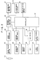
- FIG. 2 is a block diagram showing the structure of the imaging apparatus.
- FIG. 3 is a perspective view showing a structure of an imaging apparatus according to a second embodiment of the invention.
- the object of the invention namely, to reduce the size of an imaging apparatus, is attained by providing a light source constituted by a semiconductor laser which emits a light consisting of a laser beam, a Grating Light Valve and a scanning mirror.
- FIGS. 1 and 2 There will be described a first embodiment of the invention, by reference to FIGS. 1 and 2 .
- FIG. 1 is a perspective view showing a structure of an imaging apparatus 10 according to the first embodiment
- FIG. 2 is a block diagram showing the structure of the imaging apparatus 10 .
- the imaging apparatus 10 is a video camera having a housing 12 .
- a lens barrel 16 holding a taking lens 14 In the upper part of the front face of the housing 12 , there is disposed a lens barrel 16 holding a taking lens 14 , while in the upper part of the rear side of the housing 12 is disposed a viewfinder 18 having a liquid crystal display or the like.
- manipulation means 20 including an ON/OFF button, a shutter/video button, a play button and a mode button.
- the mode button is manipulated or switched for selecting whether the video camera 10 is to be operated as a usual video camera or as a projector.
- a display 19 (indicated in FIG. 2 ), which may be constituted by a liquid crystal display, is joined to one of the lateral faces of the housing 12 via a hinge mechanism.
- the display 19 is for displaying an image while the image is being captured, just like the viewfinder 18 does, or for displaying a previously taken image when the image is played back.
- an image pickup device 22 Inside the housing 12 , there are provided an image pickup device 22 , a light source 24 , a Grating Light Valve 26 , a scanning mirror 28 , a mirror drive unit 30 , a mirror mover 32 , etc.
- the image pickup device 22 is disposed in a light path of the taking lens 14 to take an image of an object as formed by means of the taking lens 14 , generating an image signal indicative of the image.
- the light source 24 is disposed above the light path of the taking lens 14 .
- the light source 24 is constituted by three semiconductor lasers (or three laser diodes), which respectively emit lights of R (red), G (green) and B (blue), frontward.
- each light is converted by the lighting lens into a light of a strip-like or slit shape. That is, a vertical dimension of each emitted light is smaller than a lateral dimension thereof.
- the Grating Light Valve 26 is disposed in front of the light source 24 and above the light path of the taking lens 14 .
- This Grating Light Valve (hereinafter simply referred to as GLV) 26 is a one-dimensional reflective display device in which optical diffraction elements each of which is ribbon-shaped are formed in a row on a silicon substrate, and constructed to be able to modulate the intensity of the light diffracted by the GLV correspondingly to a drive voltage applied thereto, as disclosed in http://www.sony.co.jp/Products/SC-HP/CXPAL/CXPAL-55/PDF/MEM S.pdf, and D. T. Amm et al. “Optical Performance of the Grating Light Valve Technology,” Projection Displays V Symposium, SPIE SPIE Proceedings Vol.EI 3634-10, February 1999.
- the drive voltage which is modulated in accordance with a projection image signal, is supplied to the GLV 26 , so that the three slit-shaped lights emitted from the light source 24 are diffracted by the GLV 26 with the amount of each diffracted light (i.e. intensity of the light) being varied depending upon the drive voltage or the projection image signal.
- the modulation of the drive voltage applied to the GLV 26 thus enables to form a multi-level one-dimensional image, and a two-dimensional image can be formed by scanning such a one-dimensional image.
- the scanning mirror 28 is formed in such a size that the scanning mirror 28 can reflect the slit-shaped lights diffracted by the GLV 26 , and is disposed between the taking lens 14 and the image pickup device 22 so as to reflect the diffracted lights toward the taking lens 14 with having the diffracted lights scan in a direction.
- the mirror drive unit 30 has a pivot shaft 3002 extending in the lateral direction, on which the scanning mirror 28 is mounted, and a pair of supporting parts 3004 rotatably supporting opposite ends of the pivot shaft 3002 .
- the pivot shaft 3002 is rotated by a motor or others so that the scanning mirror 28 is rotated or oscillated.
- the scanning mirror 28 is operated by the mirror drive unit 30 so that the slit-shaped diffracted lights scan in the vertical direction with the width direction of each diffracted light parallel to the lateral direction.
- the mirror mover 32 is fixed to the housing 12 and holds the mirror drive unit 30 such that the mirror drive unit 30 is movable in the vertical direction so that the scanning mirror 28 is shiftable between an operating position in the light path of the taking lens 14 and a non-operating or retracted position off the light path.
- the diffracted lights which are made to scan by the scanning mirror 28 as positioned at the operating position together form an image by means of, and in front of, the taking lens 14 .
- the imaging apparatus 10 further has an image processor 34 , a record/playback portion 36 , a GLV drive 38 , a light source drive 40 and a controller 42 .
- the image processor 34 generates image data by processing the image signal inputted from the image pickup device 22 .
- the record/playback portion 36 performs a recording operation for recording the image data generated by the image processor 34 onto a recording medium 37 such as a magnetic recording medium or a memory card, and a playback operation for reading the image data from the recording medium 37 to play back the image data.
- a playback operation the record/playback portion 36 transfers the image data to the viewfinder 18 and the display 19 to present the image thereon, and supply the projection image signal, which is generated based on the image data, to the GLV drive 38 .
- the GLV drive 38 applies the drive voltage in accordance with the projection image signal supplied from the record/playback portion 36 , to the GLV 26 .
- the operation of the GLV drive 38 is controlled by the controller 42 .
- the light source drive 40 drives the light source 24 based on a command outputted from the controller 42 such that each of the RGB lights is selectively emitted.
- the controller 42 switches between ON/OFF states of the imaging apparatus 10 and between operation modes of the apparatus 10 , namely, an image taking operation mode and a playback operation mode, in response to an operation of the ON/OFF button, a shutter/video button and a play button of the manipulation means 20 .
- the controller 42 also controls the scanning operation of the scanning mirror 28 by issuing commands to the mirror drive unit 30 , and controls the shifting of the scanning mirror 28 by issuing commands to the mirror mover 32 .
- the controller 42 controls the GLV drive 38 and light source drive 40 to have the GLV 38 perform, by time division, a first diffracting operation, a second diffracting operation and a third diffracting operation.
- the first diffracting operation the light of R is diffracted by the GLV 38
- the second and third diffracting operations the G and B lights are diffracted by the GLV 38 , respectively.
- the controller 42 controls the mirror mover 32 to shift the scanning mirror 28 to the retracted position, and also controls the mirror drive unit 30 to hold the scanning mirror 28 non-operated.
- the image signal outputted from the image pickup device 22 is fed to the image processor 34 which then generates the image data.
- the image data is recorded onto the recording medium 37 by the record/playback portion 36 .
- the image data is transferred to the viewfinder 18 and display 19 as well, to be presented thereon.
- the image data played by the record/playback portion 36 from the recording medium 37 is supplied to the viewfinder 18 and display 19 to be presented thereon.
- the controller 42 controls the mirror mover 32 to move the scanning mirror 28 to the operating position, and also controls the mirror drive unit 30 to initiate an operation of the scanning mirror 28 .
- the drive voltage as modulated in accordance with the projection image signal which is generated based on the image data played from the recording medium 37 by the record/playback portion 36 , is applied to the GLV 26 from the GLV drive 38 . Then, the GLV 26 diffracts the slit-shaped RGB lights emitted from the light source 24 with varying the intensity of each light based on the supplied projection image signal.
- the lights diffracted by the GLV 26 are reflected by the scanning mirror 28 toward the taking lens 14 such that the slit-shaped diffracted lights scan in a direction (i.e., the vertical direction, in this embodiment).
- the GLV 26 performs, by time division, the first, second and third diffracting operations, namely, the R light is diffracted by the GLV 38 in the first diffracting operation, while the G and B lights are diffracted in the second and third diffracting operations, respectively.
- the image with the R light is formed on the screen in the first diffracting operation, while the images with the G and B lights are formed on the screen in the second and third diffracting operations, respectively. Since the first through third diffracting operations are iterated by time division very quickly, the respective images of the R, G and B lights are synthesized as viewed, virtually producing a color image.
- the imaging apparatus 10 has the light source 24 , the GLV 26 for diffracting the lights emitted from the light source 24 , and the scanning mirror 28 for reflecting the diffracted lights toward the taking lens 14 with having the diffracted lights scan in a direction.
- This arrangement is advantageous in that the light source 24 has a reduced size compared to the white light source as conventionally used, and the cooling fan for cooling the light source 24 is omitted. Thus, reducing the size of an imaging apparatus having a projector function is facilitated.
- the present imaging apparatus is advantageous in that the battery time is elongated where the imaging apparatus is operated on electricity stored in a battery.
- FIG. 3 is a perspective view showing a structure of an imaging apparatus 10 according to the second embodiment.
- the same or similar elements as the corresponding elements in the first embodiment are denoted by the same reference numerals and detailed description thereof is omitted.
- the difference between the first and second embodiments is that the light source of the second embodiment is disposed outside the housing of the apparatus.
- a housing 12 of the imaging apparatus 10 inside a housing 12 of the imaging apparatus 10 are disposed an image pickup device 22 , a GLV 26 , a scanning mirror 28 , a mirror drive unit 30 , a mirror mover 32 , etc, similarly to the first embodiment.
- a light source 24 such that one of opposite ends of an optical fiber 25 is attached to the light source 24 to introduce, to the inside of the housing 12 , lights emitted from respective semiconductor lasers of the light source 24 .
- the other end of the optical fiber 25 is introduced into the housing 12 to be connected with the GLV 26 , so that the emitted lights are radiated toward the GLV 26 .
- the space inside the housing 12 to spare for the light source 24 is further reduced, making the imaging apparatus of the invention more advantageous in size reduction.
- the present imaging apparatus is advantageous over the conventional imaging apparatus in reducing the power consumption.
- the light source 24 comprises the three semiconductor lasers for RGB lights so that a color image is formed.
- a single semiconductor laser constitutes the light source 24 , to reduce the cost of the light source 24 and also to eliminate the necessity to control the operations of the light source 24 and GLV 26 by time division, so that the control of the light source 24 and GLV 26 is advantageously simplified.
- GLV 26 is commonly used for the three (RGB) laser lights, a plurality of GLVs may be provided for respective lights of different colors.
- the direction of scanning of the diffracted lights is not limited to the vertical direction, but may be any directions including the lateral or horizontal direction.
Abstract
An imaging apparatus having a projector function which is advantageous in reducing size is provided. A light source of the imaging apparatus is constituted by three semiconductor lasers which respectively frontward emit lights of red, green and blue, each slit-shaped. To a GLV (Grating Light Valve) is applied a drive voltage as modulated by a projection image signal, so that the GLV diffracts the three lights emitted from the light source, with varying the amount or intensity of each light in accordance with the drive voltage or projection image signal. A scanning mirror is disposed between a taking lens and an image pickup device, so as to reflect the lights diffracted by the GLV toward the taking lens, with having each diffracted slit-shaped light scan in a direction.
Description
1. Field of the Invention
The present invention relates to an imaging apparatus.
2. Description of Related Art
There has been proposed an apparatus where a projector function is additionally provided to an imaging apparatus such as a video camera, as disclosed in JP-A-5-304624 for instance.
The imaging apparatus comprises a light source and a projector lens which are respectively disposed in front and rear of a light transmissive liquid crystal panel for a viewfinder. A light emitted from the light source is transmitted through the liquid crystal panel and guided to the projector lens, by which a projection corresponding to one formed on the liquid crystal panel is formed.
In the conventional imaging apparatus, a white light source which produces a high intensity light is employed as the light source. When the white light source is operated, its temperature rises high, requiring a cooling fan for cooling the light source. Thus, some space inside the imaging apparatus is occupied by the cooling fan, hindering reduction in the size of the imaging apparatus.
The present invention has been developed in view of the above-described situation, and an object of the invention is, therefore, to provide an imaging apparatus having a projector function, which is constructed advantageously in regard to size reduction.
To attain the object, the invention provides an imaging apparatus operable to generate image data based on an image of an object formed by means of a taking lens, and record the image data on a recording medium, the imaging apparatus comprising: a light source constituted by a semiconductor laser which emits a light; a Grating Light Valve which is supplied with a projection image signal and diffracts the light emitted from the light source with varying an intensity of the light based on the projection image signal; and a scanning mirror which reflects the diffracted light toward the taking lens with having the diffracted light scan in a direction, so that the diffracted light forms the image of the object in front of the taking lens and by means of the taking lens.
Since the imaging apparatus according to the invention comprises the light source constituted by the semiconductor laser, Grating Light Valve diffracting the light emitted from the light source, and scanning mirror reflecting the diffracted light toward the taking lens with having the diffracted light scan in a direction, the size of the light source itself of the imaging apparatus is relatively small compared to the conventional apparatus where a white light source is used, omitting the cooling fan for cooling the light source. The invention thus facilitates reducing the size of an imaging apparatus having a projector function.
Other and further objects, features and advantages of the invention will appear more fully from the following description.
The object of the invention, namely, to reduce the size of an imaging apparatus, is attained by providing a light source constituted by a semiconductor laser which emits a light consisting of a laser beam, a Grating Light Valve and a scanning mirror.
<First Embodiment>
There will be described a first embodiment of the invention, by reference to FIGS. 1 and 2 .
As shown in FIG. 1 , the imaging apparatus 10 is a video camera having a housing 12.
In the upper part of the front face of the housing 12, there is disposed a lens barrel 16 holding a taking lens 14, while in the upper part of the rear side of the housing 12 is disposed a viewfinder 18 having a liquid crystal display or the like.
On the lateral faces of the housing 12, there is disposed manipulation means 20 (indicated in FIG. 2 ) including an ON/OFF button, a shutter/video button, a play button and a mode button. The mode button is manipulated or switched for selecting whether the video camera 10 is to be operated as a usual video camera or as a projector.
A display 19 (indicated in FIG. 2 ), which may be constituted by a liquid crystal display, is joined to one of the lateral faces of the housing 12 via a hinge mechanism. The display 19 is for displaying an image while the image is being captured, just like the viewfinder 18 does, or for displaying a previously taken image when the image is played back.
Inside the housing 12, there are provided an image pickup device 22, a light source 24, a Grating Light Valve 26, a scanning mirror 28, a mirror drive unit 30, a mirror mover 32, etc.
The image pickup device 22 is disposed in a light path of the taking lens 14 to take an image of an object as formed by means of the taking lens 14, generating an image signal indicative of the image.
The light source 24 is disposed above the light path of the taking lens 14. In the present embodiment, the light source 24 is constituted by three semiconductor lasers (or three laser diodes), which respectively emit lights of R (red), G (green) and B (blue), frontward.
Generating little heat, such semiconductor lasers need not be cooled by using a cooling fan and therefore occupies only a significantly small space compared to the conventional apparatus where a white light source is employed as the light source.
In the light source 24 is incorporated a lighting lens not shown, and each light is converted by the lighting lens into a light of a strip-like or slit shape. That is, a vertical dimension of each emitted light is smaller than a lateral dimension thereof.
The Grating Light Valve 26 is disposed in front of the light source 24 and above the light path of the taking lens 14.
This Grating Light Valve (hereinafter simply referred to as GLV) 26 is a one-dimensional reflective display device in which optical diffraction elements each of which is ribbon-shaped are formed in a row on a silicon substrate, and constructed to be able to modulate the intensity of the light diffracted by the GLV correspondingly to a drive voltage applied thereto, as disclosed in http://www.sony.co.jp/Products/SC-HP/CXPAL/CXPAL-55/PDF/MEM S.pdf, and D. T. Amm et al. “Optical Performance of the Grating Light Valve Technology,” Projection Displays V Symposium, SPIE SPIE Proceedings Vol.EI 3634-10, February 1999.
In the present embodiment, the drive voltage, which is modulated in accordance with a projection image signal, is supplied to the GLV 26, so that the three slit-shaped lights emitted from the light source 24 are diffracted by the GLV 26 with the amount of each diffracted light (i.e. intensity of the light) being varied depending upon the drive voltage or the projection image signal.
The modulation of the drive voltage applied to the GLV 26 thus enables to form a multi-level one-dimensional image, and a two-dimensional image can be formed by scanning such a one-dimensional image.
The scanning mirror 28 is formed in such a size that the scanning mirror 28 can reflect the slit-shaped lights diffracted by the GLV 26, and is disposed between the taking lens 14 and the image pickup device 22 so as to reflect the diffracted lights toward the taking lens 14 with having the diffracted lights scan in a direction.
The mirror drive unit 30 has a pivot shaft 3002 extending in the lateral direction, on which the scanning mirror 28 is mounted, and a pair of supporting parts 3004 rotatably supporting opposite ends of the pivot shaft 3002. The pivot shaft 3002 is rotated by a motor or others so that the scanning mirror 28 is rotated or oscillated. In the present embodiment, the scanning mirror 28 is operated by the mirror drive unit 30 so that the slit-shaped diffracted lights scan in the vertical direction with the width direction of each diffracted light parallel to the lateral direction.
The mirror mover 32 is fixed to the housing 12 and holds the mirror drive unit 30 such that the mirror drive unit 30 is movable in the vertical direction so that the scanning mirror 28 is shiftable between an operating position in the light path of the taking lens 14 and a non-operating or retracted position off the light path.
Further, the diffracted lights which are made to scan by the scanning mirror 28 as positioned at the operating position together form an image by means of, and in front of, the taking lens 14.
There will be described a structure of a control system of the imaging apparatus 10, by reference to FIG. 2 .
As shown in FIG. 2 , the imaging apparatus 10 further has an image processor 34, a record/playback portion 36, a GLV drive 38, a light source drive 40 and a controller 42.
The image processor 34 generates image data by processing the image signal inputted from the image pickup device 22.
The record/playback portion 36 performs a recording operation for recording the image data generated by the image processor 34 onto a recording medium 37 such as a magnetic recording medium or a memory card, and a playback operation for reading the image data from the recording medium 37 to play back the image data. In a playback operation, the record/playback portion 36 transfers the image data to the viewfinder 18 and the display 19 to present the image thereon, and supply the projection image signal, which is generated based on the image data, to the GLV drive 38.
The GLV drive 38 applies the drive voltage in accordance with the projection image signal supplied from the record/playback portion 36, to the GLV 26. The operation of the GLV drive 38 is controlled by the controller 42.
The light source drive 40 drives the light source 24 based on a command outputted from the controller 42 such that each of the RGB lights is selectively emitted.
The controller 42 switches between ON/OFF states of the imaging apparatus 10 and between operation modes of the apparatus 10, namely, an image taking operation mode and a playback operation mode, in response to an operation of the ON/OFF button, a shutter/video button and a play button of the manipulation means 20.
The controller 42 also controls the scanning operation of the scanning mirror 28 by issuing commands to the mirror drive unit 30, and controls the shifting of the scanning mirror 28 by issuing commands to the mirror mover 32.
Further, the controller 42 controls the GLV drive 38 and light source drive 40 to have the GLV 38 perform, by time division, a first diffracting operation, a second diffracting operation and a third diffracting operation. In the first diffracting operation, the light of R is diffracted by the GLV 38, while in the second and third diffracting operations, the G and B lights are diffracted by the GLV 38, respectively.
There will next be described operation of the imaging apparatus 10.
First, a case where the imaging apparatus 10 is operated as a usual video camera is described.
When the mode button of the manipulation means 20 is switched to a “video camera” position from a “projection” position, the controller 42 controls the mirror mover 32 to shift the scanning mirror 28 to the retracted position, and also controls the mirror drive unit 30 to hold the scanning mirror 28 non-operated.
When an image taking operation is performed in this state, the image signal outputted from the image pickup device 22 is fed to the image processor 34 which then generates the image data. The image data is recorded onto the recording medium 37 by the record/playback portion 36. The image data is transferred to the viewfinder 18 and display 19 as well, to be presented thereon.
When a playback operation is performed, the image data played by the record/playback portion 36 from the recording medium 37 is supplied to the viewfinder 18 and display 19 to be presented thereon.
Next, another case where the imaging apparatus is operated as a projector is described.
In front of the imaging apparatus 10, there is placed a screen on which the image formed by the taking lens 14 is projected.
When the mode button of the manipulation means 20 is switched to the “projector” position, the controller 42 controls the mirror mover 32 to move the scanning mirror 28 to the operating position, and also controls the mirror drive unit 30 to initiate an operation of the scanning mirror 28.
When a playback operation is performed in this state, the drive voltage as modulated in accordance with the projection image signal, which is generated based on the image data played from the recording medium 37 by the record/playback portion 36, is applied to the GLV 26 from the GLV drive 38. Then, the GLV 26 diffracts the slit-shaped RGB lights emitted from the light source 24 with varying the intensity of each light based on the supplied projection image signal.
The lights diffracted by the GLV 26 are reflected by the scanning mirror 28 toward the taking lens 14 such that the slit-shaped diffracted lights scan in a direction (i.e., the vertical direction, in this embodiment).
The diffracted lights made to scan by the scanning mirror 28 together, form an image, by means of the taking lens 14, on the screen disposed in front of the taking lens 14.
To form the image on the screen, the GLV 26 performs, by time division, the first, second and third diffracting operations, namely, the R light is diffracted by the GLV 38 in the first diffracting operation, while the G and B lights are diffracted in the second and third diffracting operations, respectively.
Therefore, the image with the R light is formed on the screen in the first diffracting operation, while the images with the G and B lights are formed on the screen in the second and third diffracting operations, respectively. Since the first through third diffracting operations are iterated by time division very quickly, the respective images of the R, G and B lights are synthesized as viewed, virtually producing a color image.
As described above, in the present embodiment the imaging apparatus 10 has the light source 24, the GLV 26 for diffracting the lights emitted from the light source 24, and the scanning mirror 28 for reflecting the diffracted lights toward the taking lens 14 with having the diffracted lights scan in a direction. This arrangement is advantageous in that the light source 24 has a reduced size compared to the white light source as conventionally used, and the cooling fan for cooling the light source 24 is omitted. Thus, reducing the size of an imaging apparatus having a projector function is facilitated.
Further, since a semiconductor laser consumes less electric power compared to the conventionally used white light source, the present imaging apparatus is advantageous in that the battery time is elongated where the imaging apparatus is operated on electricity stored in a battery.
<Second Embodiment>
There will be now described a second embodiment of the invention, by reference to FIG. 3 .
The difference between the first and second embodiments is that the light source of the second embodiment is disposed outside the housing of the apparatus.
As shown in FIG. 3 , inside a housing 12 of the imaging apparatus 10 are disposed an image pickup device 22, a GLV 26, a scanning mirror 28, a mirror drive unit 30, a mirror mover 32, etc, similarly to the first embodiment.
Outside the housing 12 is provided a light source 24 such that one of opposite ends of an optical fiber 25 is attached to the light source 24 to introduce, to the inside of the housing 12, lights emitted from respective semiconductor lasers of the light source 24.
The other end of the optical fiber 25 is introduced into the housing 12 to be connected with the GLV 26, so that the emitted lights are radiated toward the GLV 26.
In the thus constructed imaging apparatus 10 where the light source 24 is provided outside the housing 12, the space inside the housing 12 to spare for the light source 24 is further reduced, making the imaging apparatus of the invention more advantageous in size reduction. In addition, similarly to the imaging apparatus of the first embodiment, the present imaging apparatus is advantageous over the conventional imaging apparatus in reducing the power consumption.
In each of the embodiments described above, the light source 24 comprises the three semiconductor lasers for RGB lights so that a color image is formed. However, in a case where a monochrome image is to be obtained, a single semiconductor laser constitutes the light source 24, to reduce the cost of the light source 24 and also to eliminate the necessity to control the operations of the light source 24 and GLV 26 by time division, so that the control of the light source 24 and GLV 26 is advantageously simplified.
Further, although in each embodiment described above a GLV 26 is commonly used for the three (RGB) laser lights, a plurality of GLVs may be provided for respective lights of different colors.
The direction of scanning of the diffracted lights is not limited to the vertical direction, but may be any directions including the lateral or horizontal direction.
The foregoing invention has been described in terms of preferred embodiments. However, those skilled, in the art will recognize that many variations of such embodiments exist. Such variations are intended to be within the scope of the present invention and the appended claims.
Claims (17)
1. An imaging apparatus operable to generate image data based on an image of an object formed by means of a taking lens, and record the image data on a recording medium, the imaging apparatus comprising:
a light source constituted by a semiconductor laser which emits a light;
a Grating Light Valve which is supplied with a projection image signal and diffracts the light emitted from the light source with varying an intensity of the light based on the projection image signal which is used for projecting the image; and
a scanning mirror which reflects the diffracted light toward the taking lens with having the diffracted light scan in a direction, so that the diffracted light forms the image of the object in front of the taking lens and by means of the taking lens.
2. The imaging apparatus of claim 1 , further comprising a record/playback portion operable to record the image data onto the recording medium and to playback the image data from the recording medium, and
wherein the projection image signal is generated by playing back the image data from the recording medium by the record/playback portion.
3. The imaging apparatus of claim 2 , wherein the projection image signal is supplied from the record/playback portion to the Grating Light Valve.
4. The imaging apparatus of claim 1 , wherein the projection image signal is supplied from an external device connected to the imaging apparatus to the Grating Light Valve.
5. The imaging apparatus of claim 1 , further comprising a mirror mover which positions the scanning mirror in a light path of the taking lens when the image is to be formed in front of the taking lens with the diffracted light as scanning, and retracts the scanning mirror off the light path when the image data is to be recorded.
6. The imaging apparatus of claim 1 , further comprising a housing and an image pickup device which takes the image of the object as formed by the taking lens to generate an image signal for producing the image data, the housing accommodating the image pickup device, the light source and the Grating Light Valve such that the image pickup device is disposed in a light path of the taking lens while the light source and the Grating Light Valve are respectively disposed above the light path.
7. The imaging apparatus of claim 1 , further comprising a housing, and wherein the Grating Light Valve and the scanning mirror are disposed inside the housing, while the light source is disposed outside the housing and connected with the Grating Light Valve through an optical fiber.
8. The imaging apparatus of claim 1 , wherein the light source is constructed to emit three lights, which are of red, green and blue colors, while the Grating Light Valve performs, by time division, a first diffracting operation to diffract the red light, a second diffracting operation to diffract the green light, and a third diffracting operation to diffract the blue light.
9. The imaging apparatus of claim 1 , wherein the light source is constituted by three semiconductor lasers, which respectively emits a R (red), G (green) and B (blue) light.
10. The imaging apparatus of claim 1 , further comprising:
a controller configured to control a Grating Light Valve drive and a light source drive to have the Grating Light Valve perform, by time division, a first diffracting operation, a second diffracting operation and a third diffracting operation.
11. The imaging apparatus of claim 10 , wherein the first diffracting operation comprises diffracting the R light by the Grating Light Valve.
12. The imaging apparatus of claim 10 , wherein the second diffracting operation comprises diffracting the G light by the Grating Light Valve.
13. The imaging apparatus of claim 10 , wherein the third diffracting operation comprises diffracting the B light by the Grating Light Valve.
14. The imaging apparatus of claim 1 , further comprising:
a controller configured to control a mirror mover to shift the scanning mirror between a retracted position and a non-retracted position.
15. The imaging apparatus of claim 1 , further comprising:
a switch operable to select a mode of operation, said mode of operation being one of a projector mode and a video camera mode.
16. The imaging apparatus of claim 15 , further comprising:
a liquid crystal display which displays the image while the image is being captured, or displays a previously taken image when the previously taken image is played back;
an image pickup device which generates a camera image signal indicative of the image;
a magnetic recording medium which stores the image;
an image processor which generates the image data by processing the image signal inputted from the image pickup device; and
a record/playback unit which records the image data onto the magnetic recording medium, which reads the image data from the recording medium for play back.
17. The imaging apparatus of claim 16 , further comprising a controller, including:
means for switching between ON/OFF states in response to an operation of the ON/OFF button;
means for switching between a projector mode and a video mode;
means for controlling a scanning operations of the scanning mirror;
means for controlling a shifting of the scanning mirror;
means for controlling a Grating Light Valve drive;
means for controlling a light source drive; and
means for having a Grating Light Valve perform by time division, a first diffracting operation, a second diffracting operation and a third diffracting operation.
Applications Claiming Priority (2)
| Application Number | Priority Date | Filing Date | Title |
|---|---|---|---|
| JP2003-334800 | 2003-09-26 | ||
| JP2003334800A JP3831946B2 (en) | 2003-09-26 | 2003-09-26 | Imaging device |
Publications (2)
| Publication Number | Publication Date |
|---|---|
| US20050099664A1 US20050099664A1 (en) | 2005-05-12 |
| US7116455B2 true US7116455B2 (en) | 2006-10-03 |
Family
ID=34462369
Family Applications (1)
| Application Number | Title | Priority Date | Filing Date |
|---|---|---|---|
| US10/943,981 Expired - Fee Related US7116455B2 (en) | 2003-09-26 | 2004-09-20 | Imaging apparatus |
Country Status (4)
| Country | Link |
|---|---|
| US (1) | US7116455B2 (en) |
| JP (1) | JP3831946B2 (en) |
| KR (1) | KR20050030855A (en) |
| CN (1) | CN1324881C (en) |
Cited By (15)
| Publication number | Priority date | Publication date | Assignee | Title |
|---|---|---|---|---|
| US20050174627A1 (en) * | 2002-10-17 | 2005-08-11 | Sony Corporation | Image production apparatus, image display apparatus, image display method and optical modulation device adjustment apparatus |
| US20060291851A1 (en) * | 2005-02-08 | 2006-12-28 | Nikon Corporation | Digital camera with projector and digital camera system |
| US20060291046A1 (en) * | 2004-09-03 | 2006-12-28 | Akira Nakamura | Light scanning apparatus and imaging apparatus |
| US20070273849A1 (en) * | 2006-04-04 | 2007-11-29 | Seiko Epson Corporation | Projector |
| US20090284622A1 (en) * | 2008-05-19 | 2009-11-19 | Microvision, Inc. | Digital Photographing Apparatus Having a Laser Scanning Projector |
| US20180364355A1 (en) * | 2016-10-31 | 2018-12-20 | Gerard Dirk Smits | Fast scanning lidar with dynamic voxel probing |
| US10473921B2 (en) | 2017-05-10 | 2019-11-12 | Gerard Dirk Smits | Scan mirror systems and methods |
| US10477149B2 (en) | 2016-01-20 | 2019-11-12 | Gerard Dirk Smits | Holographic video capture and telepresence system |
| US10502815B2 (en) | 2015-12-18 | 2019-12-10 | Gerard Dirk Smits | Real time position sensing of objects |
| US10564284B2 (en) | 2016-12-27 | 2020-02-18 | Gerard Dirk Smits | Systems and methods for machine perception |
| US10591605B2 (en) | 2017-10-19 | 2020-03-17 | Gerard Dirk Smits | Methods and systems for navigating a vehicle including a novel fiducial marker system |
| US10725177B2 (en) | 2018-01-29 | 2020-07-28 | Gerard Dirk Smits | Hyper-resolved, high bandwidth scanned LIDAR systems |
| US10962867B2 (en) | 2007-10-10 | 2021-03-30 | Gerard Dirk Smits | Method, apparatus, and manufacture for a tracking camera or detector with fast asynchronous triggering |
| US11137497B2 (en) | 2014-08-11 | 2021-10-05 | Gerard Dirk Smits | Three-dimensional triangulation and time-of-flight based tracking systems and methods |
| US11829059B2 (en) | 2020-02-27 | 2023-11-28 | Gerard Dirk Smits | High resolution scanning of remote objects with fast sweeping laser beams and signal recovery by twitchy pixel array |
Families Citing this family (13)
| Publication number | Priority date | Publication date | Assignee | Title |
|---|---|---|---|---|
| KR100897666B1 (en) * | 2005-07-20 | 2009-05-14 | 삼성전기주식회사 | Display apparatus which scans both the forward path and backward path |
| DE102006003738A1 (en) * | 2006-01-20 | 2007-07-26 | Seereal Technologies S.A. | Wavefront forming device for direct patterning light wavefront, has electromechanical actuator that axially adjusts and tilts mirror units in direction such that mirror units form light wavefront corresponding to target light wavefront |
| TW201126249A (en) * | 2010-01-18 | 2011-08-01 | Ability Entpr Co Ltd | Photographic and projection device |
| WO2011109402A2 (en) * | 2010-03-01 | 2011-09-09 | Gerard Dirk Smits | Safety device for scanned projector and illumination systems |
| US8620151B2 (en) | 2010-03-12 | 2013-12-31 | Ability Enterprise Co., Ltd. | Photographic and projection module and electronic system having the same |
| TWI457687B (en) * | 2010-03-26 | 2014-10-21 | Ability Entpr Co Ltd | Image-projecting and image-capturing system and method |
| WO2012054231A2 (en) | 2010-10-04 | 2012-04-26 | Gerard Dirk Smits | System and method for 3-d projection and enhancements for interactivity |
| US9081262B2 (en) * | 2011-10-07 | 2015-07-14 | Massachusetts Institute Of Technology | Methods and apparatus for ultra-fast camera |
| US8711370B1 (en) | 2012-10-04 | 2014-04-29 | Gerard Dirk Smits | Scanning optical positioning system with spatially triangulating receivers |
| US8971568B1 (en) | 2012-10-08 | 2015-03-03 | Gerard Dirk Smits | Method, apparatus, and manufacture for document writing and annotation with virtual ink |
| US9810913B2 (en) | 2014-03-28 | 2017-11-07 | Gerard Dirk Smits | Smart head-mounted projection system |
| US10043282B2 (en) | 2015-04-13 | 2018-08-07 | Gerard Dirk Smits | Machine vision for ego-motion, segmenting, and classifying objects |
| CN105842971B (en) * | 2016-05-27 | 2018-05-11 | 华为技术有限公司 | A kind of projection arrangement and method |
Citations (4)
| Publication number | Priority date | Publication date | Assignee | Title |
|---|---|---|---|---|
| JPH05304624A (en) | 1992-04-24 | 1993-11-16 | Sony Corp | Video camera |
| JPH11122238A (en) | 1997-10-17 | 1999-04-30 | Ricoh Co Ltd | Network system |
| US20030031215A1 (en) * | 2001-08-10 | 2003-02-13 | Kane Thomas J. | Compound light source employing passive Q-switching and nonlinear frequency conversion |
| US20040090599A1 (en) * | 2002-10-16 | 2004-05-13 | Eastman Kodak Company | Light modulation apparatus using a VCSEL array with an electromechanical grating device |
Family Cites Families (2)
| Publication number | Priority date | Publication date | Assignee | Title |
|---|---|---|---|---|
| CA2373284A1 (en) * | 1999-05-14 | 2000-11-23 | 3D Metrics, Incorporated | Color structured light 3d-imaging system |
| CN1208654C (en) * | 2000-12-07 | 2005-06-29 | 索尼公司 | Image projector, projected image pattern, laser driver, imaging device |
-
2003
- 2003-09-26 JP JP2003334800A patent/JP3831946B2/en not_active Expired - Fee Related
-
2004
- 2004-09-20 US US10/943,981 patent/US7116455B2/en not_active Expired - Fee Related
- 2004-09-21 KR KR1020040075461A patent/KR20050030855A/en not_active Application Discontinuation
- 2004-09-24 CN CNB2004100800906A patent/CN1324881C/en not_active Expired - Fee Related
Patent Citations (4)
| Publication number | Priority date | Publication date | Assignee | Title |
|---|---|---|---|---|
| JPH05304624A (en) | 1992-04-24 | 1993-11-16 | Sony Corp | Video camera |
| JPH11122238A (en) | 1997-10-17 | 1999-04-30 | Ricoh Co Ltd | Network system |
| US20030031215A1 (en) * | 2001-08-10 | 2003-02-13 | Kane Thomas J. | Compound light source employing passive Q-switching and nonlinear frequency conversion |
| US20040090599A1 (en) * | 2002-10-16 | 2004-05-13 | Eastman Kodak Company | Light modulation apparatus using a VCSEL array with an electromechanical grating device |
Non-Patent Citations (2)
| Title |
|---|
| "Grating Light Valve", Featuring, MEMS, 4 pages (with partial English translation). |
| David T. Amm, et al., "Optical Performance of the Grating Light Valve Technology", Projection Display V Symposium, vol. 3634, 1999, pp. 71-78. |
Cited By (25)
| Publication number | Priority date | Publication date | Assignee | Title |
|---|---|---|---|---|
| US20050174627A1 (en) * | 2002-10-17 | 2005-08-11 | Sony Corporation | Image production apparatus, image display apparatus, image display method and optical modulation device adjustment apparatus |
| US7339753B2 (en) * | 2004-09-03 | 2008-03-04 | Sony Corporation | Light scanning apparatus and imaging apparatus |
| US20060291046A1 (en) * | 2004-09-03 | 2006-12-28 | Akira Nakamura | Light scanning apparatus and imaging apparatus |
| US7653304B2 (en) * | 2005-02-08 | 2010-01-26 | Nikon Corporation | Digital camera with projector and digital camera system |
| US8498532B2 (en) | 2005-02-08 | 2013-07-30 | Nikon Corporation | Digital camera with projector and digital camera system |
| US20060291851A1 (en) * | 2005-02-08 | 2006-12-28 | Nikon Corporation | Digital camera with projector and digital camera system |
| US20100002123A1 (en) * | 2005-02-08 | 2010-01-07 | Nikon Corporation | Digital camera with projector and digital camera system |
| US20070273849A1 (en) * | 2006-04-04 | 2007-11-29 | Seiko Epson Corporation | Projector |
| US10962867B2 (en) | 2007-10-10 | 2021-03-30 | Gerard Dirk Smits | Method, apparatus, and manufacture for a tracking camera or detector with fast asynchronous triggering |
| US11531257B2 (en) | 2007-10-10 | 2022-12-20 | Gerard Dirk Smits | Method, apparatus, and manufacture for a tracking camera or detector with fast asynchronous triggering |
| US7982793B2 (en) * | 2008-05-19 | 2011-07-19 | Microvision, Inc. | Digital photographing apparatus having a laser scanning projector |
| US20090284622A1 (en) * | 2008-05-19 | 2009-11-19 | Microvision, Inc. | Digital Photographing Apparatus Having a Laser Scanning Projector |
| US11137497B2 (en) | 2014-08-11 | 2021-10-05 | Gerard Dirk Smits | Three-dimensional triangulation and time-of-flight based tracking systems and methods |
| US10502815B2 (en) | 2015-12-18 | 2019-12-10 | Gerard Dirk Smits | Real time position sensing of objects |
| US10477149B2 (en) | 2016-01-20 | 2019-11-12 | Gerard Dirk Smits | Holographic video capture and telepresence system |
| US10451737B2 (en) * | 2016-10-31 | 2019-10-22 | Gerard Dirk Smits | Fast scanning with dynamic voxel probing |
| US20180364355A1 (en) * | 2016-10-31 | 2018-12-20 | Gerard Dirk Smits | Fast scanning lidar with dynamic voxel probing |
| US10564284B2 (en) | 2016-12-27 | 2020-02-18 | Gerard Dirk Smits | Systems and methods for machine perception |
| US11709236B2 (en) | 2016-12-27 | 2023-07-25 | Samsung Semiconductor, Inc. | Systems and methods for machine perception |
| US10473921B2 (en) | 2017-05-10 | 2019-11-12 | Gerard Dirk Smits | Scan mirror systems and methods |
| US11067794B2 (en) | 2017-05-10 | 2021-07-20 | Gerard Dirk Smits | Scan mirror systems and methods |
| US10935989B2 (en) | 2017-10-19 | 2021-03-02 | Gerard Dirk Smits | Methods and systems for navigating a vehicle including a novel fiducial marker system |
| US10591605B2 (en) | 2017-10-19 | 2020-03-17 | Gerard Dirk Smits | Methods and systems for navigating a vehicle including a novel fiducial marker system |
| US10725177B2 (en) | 2018-01-29 | 2020-07-28 | Gerard Dirk Smits | Hyper-resolved, high bandwidth scanned LIDAR systems |
| US11829059B2 (en) | 2020-02-27 | 2023-11-28 | Gerard Dirk Smits | High resolution scanning of remote objects with fast sweeping laser beams and signal recovery by twitchy pixel array |
Also Published As
| Publication number | Publication date |
|---|---|
| CN1602049A (en) | 2005-03-30 |
| JP2005102020A (en) | 2005-04-14 |
| KR20050030855A (en) | 2005-03-31 |
| CN1324881C (en) | 2007-07-04 |
| JP3831946B2 (en) | 2006-10-11 |
| US20050099664A1 (en) | 2005-05-12 |
Similar Documents
| Publication | Publication Date | Title |
|---|---|---|
| US7116455B2 (en) | Imaging apparatus | |
| US8807758B2 (en) | Light source unit and projector | |
| US8616710B2 (en) | Projector with luminescent wheel and control unit for equalizing illumination | |
| KR101257835B1 (en) | Light source unit and projector | |
| US7303291B2 (en) | Illumination apparatus and video projection display system | |
| US8540379B2 (en) | Image display device and information processing apparatus including the same | |
| US20150077645A1 (en) | Image-projection module | |
| JP2004514925A (en) | Dual mode system of peeping and projection display | |
| KR20120039496A (en) | Image display device and information processing device including it | |
| JP4239107B2 (en) | Light source device and projector | |
| JP5136820B2 (en) | Light source unit and projector | |
| CN107831632B (en) | Light source device and projection device | |
| JP2007065677A (en) | Picture display apparatus | |
| JP4817274B1 (en) | Image display device | |
| US20210149288A1 (en) | Light source unit and projector | |
| US8541729B2 (en) | Image display system having a detection of an overlapping in the output timing of laser beams | |
| JPH0968917A (en) | Color holography device | |
| JP2004191839A (en) | Projector | |
| JP2004245987A (en) | Projector | |
| JP2007005352A (en) | Laser light source device, display, and projector | |
| JP2004279498A (en) | Image projection apparatus | |
| JP2006227469A (en) | Projector | |
| JP2022086240A (en) | projector | |
| JP4786766B1 (en) | Image display device | |
| JP2002525695A (en) | Projection display system and apparatus having high bandwidth wireless communication function of projection display data |
Legal Events
| Date | Code | Title | Description |
|---|---|---|---|
| AS | Assignment |
Owner name: SONY CORPORATION, JAPAN Free format text: ASSIGNMENT OF ASSIGNORS INTEREST;ASSIGNOR:YAMAOKA, NOBUSUKE;REEL/FRAME:016130/0604 Effective date: 20041221 |
|
| REMI | Maintenance fee reminder mailed | ||
| LAPS | Lapse for failure to pay maintenance fees | ||
| STCH | Information on status: patent discontinuation |
Free format text: PATENT EXPIRED DUE TO NONPAYMENT OF MAINTENANCE FEES UNDER 37 CFR 1.362 |
|
| FP | Lapsed due to failure to pay maintenance fee |
Effective date: 20101003 |