US7104708B2 - Sector drive unit for camera - Google Patents
Sector drive unit for camera Download PDFInfo
- Publication number
- US7104708B2 US7104708B2 US10/825,550 US82555004A US7104708B2 US 7104708 B2 US7104708 B2 US 7104708B2 US 82555004 A US82555004 A US 82555004A US 7104708 B2 US7104708 B2 US 7104708B2
- Authority
- US
- United States
- Prior art keywords
- sector
- sectors
- retaining
- actuator
- unit
- Prior art date
- Legal status (The legal status is an assumption and is not a legal conclusion. Google has not performed a legal analysis and makes no representation as to the accuracy of the status listed.)
- Expired - Fee Related, expires
Links
- 230000007246 mechanism Effects 0.000 claims abstract description 30
- 230000003068 static effect Effects 0.000 claims description 26
- 230000000717 retained effect Effects 0.000 claims description 20
- 230000033001 locomotion Effects 0.000 claims description 11
- 230000004044 response Effects 0.000 claims description 2
- 238000001514 detection method Methods 0.000 description 22
- 230000001360 synchronised effect Effects 0.000 description 14
- 230000005611 electricity Effects 0.000 description 8
- 230000008859 change Effects 0.000 description 4
- 230000009467 reduction Effects 0.000 description 3
- 230000002829 reductive effect Effects 0.000 description 3
- 230000009471 action Effects 0.000 description 2
- 230000005540 biological transmission Effects 0.000 description 2
- 230000002441 reversible effect Effects 0.000 description 2
- 238000013500 data storage Methods 0.000 description 1
- 230000004907 flux Effects 0.000 description 1
- 230000000977 initiatory effect Effects 0.000 description 1
- 230000000452 restraining effect Effects 0.000 description 1
Images


Classifications
-
- G—PHYSICS
- G03—PHOTOGRAPHY; CINEMATOGRAPHY; ANALOGOUS TECHNIQUES USING WAVES OTHER THAN OPTICAL WAVES; ELECTROGRAPHY; HOLOGRAPHY
- G03B—APPARATUS OR ARRANGEMENTS FOR TAKING PHOTOGRAPHS OR FOR PROJECTING OR VIEWING THEM; APPARATUS OR ARRANGEMENTS EMPLOYING ANALOGOUS TECHNIQUES USING WAVES OTHER THAN OPTICAL WAVES; ACCESSORIES THEREFOR
- G03B9/00—Exposure-making shutters; Diaphragms
- G03B9/08—Shutters
- G03B9/10—Blade or disc rotating or pivoting about axis normal to its plane
- G03B9/18—More than two members
Definitions
- the present invention relates to a sector drive unit for a camera for driving, for example, a diaphragm device of a camera or a light-shielding device for a digital camera.
- a mechanism for opening and closing an aperture by pivotal movement of sectors is employed.
- the size of a diaphragm opening can be adjusted by pivoting the sectors by a drive motor, or the aperture can be opened or closed.
- the sectors are driven by operating the drive motor so that it outputs a sufficient amount of rotation for opening and closing the aperture by the sectors.
- the drive motor is driven by an electric current having a number of drive pulses corresponding to the amount of movement of the sectors.
- the sectors are closed for protecting the image pickup device when not taking a picture, and a light-shielding curtain is retracted from the aperture to open the aperture when taking a picture, and then the light-shielding curtain is moved over the aperture again to close the aperture after having taken the picture.
- the drive motor is always supplied with electricity.
- a sector drive unit for a camera includes a first actuator for driving sectors to open and close an aperture formed on a base plate, a drive force transmitting mechanism for transmitting the driving force of the first actuator to the sectors, a sector retaining unit for retaining the sectors at a position for opening the aperture and a position for closing the aperture, and a second actuator for driving the sector retaining unit to a position not to retain the sectors.
- the sector drive unit includes the sector retaining unit for retaining the sectors at the opened position and the closed position and is configured to be driven by the second actuator, which is different form the actuator for driving the sectors.
- the sector retaining unit is provided for preventing the sectors from opening accidentally by an impact or the like when the sectors are at the opened position or at the closed position, and the operation of the sector retaining unit is ensured by being driven by the second actuator.
- the sector drive unit of the present invention is also employed for driving the sectors of a diaphragm device forming a diaphragm opening smaller than the aperture formed on the base plate.
- the sectors are driven by the first actuator.
- the sector retaining unit can be driven by the second actuator and is characterized in that the sectors are reliably retained at a selected aperture value.
- the diaphragm device can prevent the sectors from moving accidentally by the operation of the sector retaining unit when the selected aperture value is to be continuously retained.
- the drive force transmitting mechanism in the respective sector drive units for a camera includes a drive member provided on a rotary shaft of the first actuator, and an operating member for operating the sectors in response to a driving force exerted by the drive member.
- the sector retaining unit is formed of a locking member provided so as to be moved in or retracted from the operating area of the operating member, and the sector retaining unit is configured to restrict the operation of the operating member when the locking member is moved in the operating area of the operating member, and release the restricted state of the operating member when the locking member is retracted from the operating area.
- the locking member is, as described above, driven by the second actuator which is different from the actuator for driving the sectors.
- the drive circuit of the actuator may be simple, thereby reducing the product cost. Since the second actuator is not supplied with electricity when the locking member is moved in the operating area of the operating member and is restraining the operating member, reduction of power consumption is achieved. In addition, when the sector retaining unit is employed as the light-shielding device of a digital camera, since the electricity is not supplied to the sector retaining unit when the aperture is fully opened, generation of noise when the image pickup device is reading the image is prevented.
- the second actuator is configured in such a manner that the supply of power is turned OFF when the sector retaining unit is at the sector retaining position, and the supply of power is turned ON when it is at a position not retaining the sectors. Accordingly, electricity must be supplied only when the sectors are in operation, and no electric power is necessary when the sectors are in a static state. Therefore, it contributes to reduce the power consumption, and in the case of a digital camera, generation of noise when the image pickup device is reading the image with the aperture open can be prevented.
- FIG. 1 is a plan view showing a state in which an aperture is fully closed and a sector retaining unit retains the sectors in a closed state;
- FIG. 2 is a plan view showing a state in which the aperture is fully closed and the sector retaining unit does not retain the sectors;
- FIG. 3 is a plan view showing a state in which the aperture is fully opened and the sector retaining unit retains the sectors in an opened state;
- FIG. 4 is a plan view showing a state in which the aperture is fully opened and the sector retaining unit does not retain the sectors;
- FIG. 5 is an enlarged view showing a state in which a locking member of a sector retaining unit is retracted
- FIG. 6 is an enlarged view showing a state in which the locking member of the sector retaining unit is moved in;
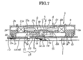
- FIG. 7 is an enlarged cross-sectional view of a drive unit
- FIG. 8 is a timing chart showing the operation of the embodiment shown in FIGS. 1–7 ;
- FIG. 9 is a front view showing an example in which the present invention is applied to a diaphragm device as another embodiment.
- FIG. 10 is a front view showing an example in which the present invention is applied to the diaphragm device as another embodiment.
- FIG. 1 to FIG. 4 are enlarged views showing a principal portion of the light shielding device described above.
- the light-shielding device is structurally similar to a focal plane shutter in that an aperture can be opened and closed by a group of vanes or sectors which superimpose and deploy with each other. However, it does not have a front curtain and a rear curtain as in the case of the focal plane shutter, but has simply one light-shielding curtain which corresponds to either the front or the rear curtain.
- a drive mechanism for opening and closing the sectors can easily be attached to or detached from a base plate 1 as a sector drive unit 2 .
- the base plate 1 (only the left half being shown in the drawing) is formed of a plate member formed substantially into a rectangular shape, and an aperture 1 a is provided at a position near the center thereof.
- the sector drive unit 2 for driving the sectors is mounted on the front surface (front side of the drawing) of the base plate 1 on the left side of the aperture 1 a .
- the sector drive unit 2 is positioned by positioning pins 1 b (only one of which is shown) projected from the front surface of the base plate 1 , and fixed by screws 10 , 10 as fixing members (see FIG. 7 ).
- a light-shielding curtain is provided on the base plate 1 at the position on the backside of the sector drive unit 2 , so that the opening and closing operation of the aperture 1 a can be carried out by the sector drive unit 2 .
- the light-shielding curtain includes a plurality of sectors 12 , only one of which is shown in the figure as being representative.
- the sector drive unit 2 includes various elements assembled in a unit case 3 , which can easily be attached to and detached from the base plate 1 .
- the sector drive unit 2 includes mainly a first actuator 4 , a synchronous switch 5 as a sector position detecting unit which will be described later, a drive force transmitting mechanism 7 , and a sector retaining unit 19 .
- the unit case 3 is represented only in outline form in FIGS. 1–4 , which omit a printed board P and a top plate 3 a of a support plate 3 (See FIG. 7 ) for the sake of more clearly showing the internal structure.
- the sector drive unit 2 is positioned on one surface (front surface) of the base plate 1 via a positioning pin 1 b and is fixed to the base plate 1 via the screws 10 , as shown in FIG. 7 .
- Sectors 12 (only one of which is shown) comprise a light-shielding curtain capable of opening and closing the aperture 1 a by means of the drive force transmitting mechanism 7 , and sector arms 13 , 14 are provided on the other surface (back surface) of the base plate 1 .
- the first actuator 4 is an electromagnetic actuator which, in this embodiment, is one of the known type pulse motors and includes a stator 4 a , an energizeable drive coil 4 b , and a rotor 4 c formed of a permanent magnet.
- the first actuator 4 employs a system of driving by a constant voltage circuit, and the strength of the magnetic force can be adjusted by adjusting an electric current.
- the first actuator 4 has a static stable position in which the rotor 4 c is retained when no power is supplied and which is defined by the positions of magnetic poles on the rotor 4 c and magnetic poles on the stator 4 a .
- the static stable position is determined by the number of magnetic poles of the rotor 4 c and the number of magnetic poles provided on the inner periphery of the recess of the stator 4 a , which surrounds the rotor. In this case, two static stable positions are provided by the combination of two magnetic poles on the rotor and four magnetic poles on the stator.
- the first actuator 4 is secured to the top plate 3 a of the unit case 3 by an intermediate member 6 in a state of being pressed against the top plate 3 a , and a rotary shaft 4 d formed integrally with the rotor 4 c is provided so as to penetrate the intermediate member 6 and project from the lower surface thereof.
- a drive member 8 which constitutes part of the drive force transmitting mechanism 7 is provided at the extremity (lower end in FIG. 7 ) of the rotary shaft 4 d of the first actuator 4 .
- An operating member 9 being interlockable with the drive member 8 , is pivotably supported by a shaft supporting device 6 b projecting from the center of the lower surface of the intermediate member 6 .
- a transmission gear mechanism is established by engagement between driven teeth 9 a of the operating member 9 and driving teeth 8 a of the drive member 8 , and the operating member 9 is interlockable with the drive member 8 .
- the drive member 8 is formed of a fan-shaped plate member fanning out to a small extent, and the narrow end portion of the fan is secured to the rotary shaft 4 d of the first actuator 4 so as to be capable of integrally rotating therewith.
- An arcuate portion formed at the extremity of the drive member 8 corresponds to the driving teeth 8 a formed by cutting the gear into the teeth-shape.
- the operating member 9 has a portion formed into an arcuate shape in a range of a predetermined distance from the rotational center, and this arcuate portion is provided along part of the periphery thereof with the driven teeth 9 a , which are engageable with the driving teeth 8 a of the drive member. Part of the arcuate portion which is not provided with the driven teeth 9 a extends outward and is formed into a lever member 9 b .
- a drive pin 9 d for driving the sectors 12 is provided on the lower surface of the extremity of the lever member 9 b .
- the drive pin 9 d can drive the sectors 12 via a sector arm 13 provided on the back side of the base plate 1 through an arcuate groove 1 c formed on the base plate 1 .
- an engaging arm 9 c On the outer periphery of a bearing member of the operating member 9 , there is provided an engaging arm 9 c , extending in a direction slightly different from that of the lever member 9 b and, at the same time, extending to an extent not protruding from the upper surface of the lever member 9 b , and formed integrally with the operating member 9 .
- a contactable pin 9 f At the extremity of the engaging arm 9 c , there is formed a contactable pin 9 f , which will be described later, projecting upward.
- the engaging arm 9 c serves to generate a signal indicating the change of the state of the synchronous switch 5 and constitutes a member of the sector retaining unit 19 described later.
- the drive force transmitting mechanism 7 is configured in such a manner that the drive member 8 pivots in accordance with the rotation of the rotor 4 c of the first actuator 4 , and the operating member 9 interlocked with the drive member 8 via the transmission gear mechanism can pivot by an angle corresponding to the ratio of the distances from the respective pivots to the pitch circles of the respective teeth.
- the pivotal angle of the operating member 9 is the same as the pivotal angle of the sector arm 13 , and the opening-and-closing amount of the sectors 12 is determined by the pivotal angle of the operating member 9 and the length of the sector arm 13 .
- the synchronous switch 5 used in the sector drive unit 2 includes a detection spring 17 and a detection pin 18 .
- the synchronous switch 5 is a sector position detection sensor for detecting the state of the sectors 12 .
- the detection spring 17 employed here is a helical torsion coil spring having straight portions extending in opposite directions at the ends. The coil portion of the spring is fitted on a shaft 3 d projecting from the unit case 3 so that one of the straight portions extending from the coil portion can abut against the contactable pin 9 f provided at the extremity of the engaging arm 9 c formed integrally with the operating member 9 .
- the pivotal range of the other straight portion can be restricted by abutting against a projection 6 c projecting from the upper surface of the intermediate member 6 .
- the other straight portion is bent upward at a right angle at the extremity thereof, though it is not shown, and the extremity is brought into electrical communication with the printed board P provided on the upper surface of the top plate 3 a of the unit case 3 to function to as an information output section, so that the detected data can be supplied to the CPU (not shown) of the camera body.
- the CPU controls the various operations of the camera in a manner well known in art.
- the detection pin 18 is formed of a conductive round rod member, and the detection pin 18 is supported between the printed board P and the intermediate member 6 at both ends, so as to electrically communicate with the printed board P.
- the detection pin 18 is arranged at the position in which the intermediate position of the straight portion of the detection spring 17 can abut against the detection pin 18 when the sectors 12 leave the aperture 1 a in a fully opened state, and the straight portion can stay spaced apart therefrom when the aperture 1 a is closed.
- Detected data indicating whether the detection spring 17 and the detection pin 18 are in contact with each other or out of contact with each other can be supplied from the terminals 17 a , 18 a provided on the printed board P.
- Such a contacting action is performed by elastically deforming the detection spring 17 by the pivotal movement of the operating member 9 via the contactable pin 9 f.
- a light-shielding curtain for opening and closing the aperture 1 a is provided on the other surface (back surface) of the base plate 1 .
- the light-shielding curtain includes the plurality of sectors 12 , the first sector arm 13 for driving the sectors 12 , and the second sector arm 14 provided above the first sector arm 13 , constituting a parallel link mechanism.
- the first sector arm 13 being positioned on the lower side, is pivotably supported by a shaft 1 d (See FIG. 7 ) provided concentrically with the rotational center of the operating member 9 on the lower surface side of the base plate 1 .
- the drive pin 9 d of the operating member 9 penetrates the arcuate groove 1 c on the base plate 1 and is inserted into a hole formed at the intermediate position of the first sector arm 13 , so that the arm can be driven by the operating member.
- the extremity of the first sector arm 13 is pivotably connected to the sectors 12 via connecting pins 13 a .
- the second sector arm 14 positioned above the first sector arm 13 is pivotably supported on the lower surface of the base plate 1 at a position a little apart from the position where the first sector arm is 13 supported.
- the extremity of the second sector arm 14 is pivotably connected to the sectors 12 , so that the sectors 12 constitute a parallel link mechanism.
- the sector retaining unit 19 for retaining the sectors 12 in the opened state or in the closed state is provided below the drive force transmitting mechanism 7 in proximity thereto.
- the sector retaining unit 19 includes the engaging arm 9 c formed integrally with the operating member 9 , the second actuator 21 , and a locking member 23 .
- the second actuator 21 is an electromagnetic actuator which, in this embodiment, employs a known type of pulse motor having a stator 21 a , an energizeable drive coil 21 b , and a rotor 21 c , and the second actuator 21 functions like a solenoid in that the rotor 21 c rotates by a predetermined rotational angle when supplied with one pulse of electricity, and returns to the original position when the supply of power is turned OFF.
- the rotational angle of the rotor 21 c is determined by the number of poles of the stator 21 a , and is set to about 30° in this embodiment.
- the locking member 23 is formed of an inverted L-shaped plate member and is secured to the rotary shaft of the second actuator 21 which projects downward from the intermediate member 6 .
- the locking member 23 is configured so that a hook portion 23 a can be moved into and retracted from the operating area of the operating member 9 (engaging arm 9 c ) by being pivoted in the range of the above-described rotational angle.
- the sectors 12 are kept free (See FIG. 6 ).
- the locking member 23 is moved into the operating area, the sectors 12 are restricted in the state of being closed ( FIG. 1 ) or being opened ( FIG. 3 ) (See FIG. 5 ).
- FIG. 7 is an enlarged cross section of the respective mechanisms of the sector drive unit 2 .
- the first actuator 4 , the synchronous switch 5 , and the second actuator 21 of the drive mechanism of the sector drive unit 2 are fixed by the intermediate member 6 mounted to one of the surfaces (lower surface in FIG. 3 ) of the unit case 3 .
- the top plate or cover 3 a of the unit case 3 is formed of a rectangular plate member and is provided with locking portions 3 b , . . . for detachably connecting the top plate 3 a to the intermediate member 6 around the periphery thereof.
- the intermediate member 6 retains the first actuator 4 , the synchronous switch 5 , and the second actuator 21 between the top plate 3 a of the unit case 3 and the upper surface of the intermediate member 6 , and the intermediate member 6 is provided with mounting portions 6 f , 6 g for mounting the intermediate member 6 to the base plate 1 .
- the intermediate member 6 supports the drive force transmitting mechanism 7 and the sector retaining unit 23 on the lower surface, in addition to the parts described above. Since the sector drive unit 2 unitized in the manner described above can easily be attached to and detached from the base plate 1 , it can be interchangeably mounted to various base plates and sectors.
- An urging spring 16 for urging the first sector arm 13 in the direction to open the sectors 12 is provided on the back surface of the base plate 1 .
- the urging spring 16 comprises a helical torsion coil spring having a coil portion inserted onto the shaft 1 d , which supports the first sector arm 13 , so that one of the straight portions extending from the coil portion can abut against a locking projection 1 e projecting on the back surface of the base plate 1 .
- the other straight portion of the urging spring 16 abuts against the side portion of the first sector arm 13 to urge the arm in the direction to open the sectors 12 .
- One of the functions of the urging spring 16 is to facilitate the opening operation of the sectors 12 by urging the sector arm 13 in the opening direction at the time of a shutter release operation when the sectors 12 are at the initial position.
- Another function of the urging spring 16 is to reduce the play or gap and thus the rattling generated between the drive force transmitting mechanism 7 and the sectors 12 by urging them in one direction, which is known as “positional adjustment,” when the aperture 1 a is brought into an opened state.
- the urging spring 16 and the sectors 12 are protected by a sector retaining plate 15 .
- connection between the base plate 1 and the sector drive unit 2 is achieved by aligning positioning pins 1 b , provided at a plurality of locations on the upper surface of the base plate 1 and positioning holes 6 a formed on the mounting portions 6 f , 6 g of the intermediate member 6 , pressing both of them toward each other, and securing them with the screws 10 as fixing members.
- the sector drive unit 2 is mounted to the base plate 1 , the operating member 9 pivotably supported by the shaft 6 b projected from the intermediate member 6 is stably supported by a projection 1 g projected from the base plate 1 , and the drive pin 9 b penetrates the arcuate groove 1 c of the base plate and projects toward the back side thereof.
- a sector drive coil designates the drive coil 4 b of the first actuator 4 in the above-described configuration, and in this case, the direction of the electric current that causes the rotor 4 c to open the aperture 1 a is designated as minus ( ⁇ ), and an electric current in the opposite direction is designated as plus (+).
- a locking member drive coil designates the drive coil 21 b of the second actuator 21 .
- Exposure of the image pickup device designates the operation of converting an image of the imaged object into a digital signal.
- the abscissa in FIG. 8 designates time, and the ratios of the lengths of the time periods are not shown as the actual ratios and have been exaggerated for the sake of convenience of description.
- the CPU controls the supply of power to the components in accordance with the selected mode of operation of the camera.
- the sectors 12 close the aperture 1 a .
- the operating member 9 and the sectors 12 stand still at the initial position (static stable position).
- the detection spring 17 and the detection pin 18 of the synchronous switch 5 abut against each other (short-circuited).
- the locking member 23 is in the operation area of the operating member 9 (engaging arm 9 c ) and retains the sectors 12 in the closed state (See FIG. 5 ) by locking the operating member 9 .
- a release switch (not shown) is turned ON, a positive electric current (+) for closing the sectors 12 is supplied from the CPU.
- positional adjustment of the sectors 12 is performed for eliminating free play and rattling among the components generated by the previous picture-taking operation, so that picture-to-picture errors are reduced.
- the release switch is turned ON, power to the locking member drive coil 21 b of the second actuator 21 is turned ON. Therefore, as shown in FIG. 2 , the locking member 23 is retracted from the operating area of the operating member 9 and accordingly, the engagement with the engaging arm 9 c is also released, whereby the operating member 9 is released from the locked state (See FIG. 6 ).
- a negative electric current ( ⁇ ) is flown in the direction opposite from the case of positional adjustment performed previously by the CPU with respect to the sector drive coil 4 b of the first actuator 4 . Accordingly, the rotor 4 c rotates counterclockwise, and the operation to open the sectors 12 is initiated via the drive force transmitting mechanism 7 . Though the aperture 1 a is completely opened as shown in FIG. 3 upon completion of the opening operation of the sectors 12 , a slightly higher negative electric current is flown to the drive coil 4 b for a short interval to prevent bounding or rebounding of the sectors and to perform positional adjustment of the components.
- the power supply to the second actuator 21 is turned OFF, and the rotor 21 c is automatically returned to its original position. Therefore, the locking member 23 is moved again into the operating area of the operating member 9 , and in turn restricts the movement of the operating member 9 by locking the engaging arm 9 c on the outside of the hook portion 23 a . Consequently, the sectors 12 are retained in an opened state in which the aperture 1 a is open. When the sectors 12 are retained in the opened state, the power supply to the sector drive coil 4 b is turned OFF.
- the contactable pin 9 f provided upright on the engaging arm 9 c abuts against one of the straight portions of the detection spring 17 and presses the spring counterclockwise. Therefore, the detection spring 17 moves away from the detection pin 18 thereby opening the synchronous switch 5 (See FIG. 3 ), and signal data generated by the change of the state is supplied to the CPU.
- the CPU receives the signal data indicating the change of state of the synchronous switch 5 and verifies that the aperture 1 a is in the opened state, and then the CPU supplies an exposure-start signal to the image pickup device to initiate an exposure. Since the exposure operation, which in this embodiment is image reading by the image pickup device, is performed with no power being applied to the drive coils of the actuators, generation of noise is prevented and power consumption is reduced.
- the locking member 23 When the sectors 12 are in motion, the locking member 23 continues to be retracted from the operating area of the operating member 9 , and when the sectors 12 are completely closed, the power supply to the locking member drive coil 21 b is turned OFF, and the locking member 23 moves again into the operating area of the operating member 9 to restrict the operating member 9 . Since the operating member 9 is rotated counterclockwise at this time, the contactable pin 9 f which has been pressing the detection spring 17 of the synchronous switch 5 moves away from the detection spring 17 , and hence the detection spring 17 automatically returns to its original position. Accordingly, the straight portion of the detection spring 17 moves away form the detection pin 18 thereby opening the synchronous switch 5 and changes the direction of the output signal. The CPU receives this output and verifies initiation of the closing operation of the aperture 1 a.
- the sectors 12 are returned to their original position shown in FIG. 1 .
- the power supplied to the drive coil 4 b of the first actuator 4 is continued in the same direction to the drive coil 4 b for a predetermined time period for positional adjustment even after the returning motion of the drive force transmitting mechanism 7 and the sectors 12 is completed, and then the power is turned OFF to return them to their initial position.
- image data accumulated in the image pickup device by exposure is supplied to the CPU, whereby one operation to take a picture is completed.
- Data read by the image pickup device is supplied to the storage device in the camera body and is stored there. Upon completion of data storage, one picture-taking action is completed.
- the first actuator is configured to be driven by a constant voltage circuit.
- it can be driven by a constant current circuit, as a matter of course. Since the strength of the magnetic flux of the drive coil is proportional to the electric current, this relationship can be stabilized more advantageously with the constant current circuit.
- the constant voltage circuit is convenient for controlling the sectors because the speed of movement of the sectors can be adjusted by changing the driving current during normal or reverse rotation of the actuator, and hence the constant voltage circuit is employed in this embodiment.
- the diaphragm device may be, for example, like that described in a related application filed by the present applicant (See JP-A-2001-281722, FIG. 1 to FIG. 5 ), and as shown in FIG. 9 comprises an operating member 59 (which corresponds to the operating member 9 in FIG. 1 ) of the sector drive unit 2 according to the present invention is provided on the left side of a circular aperture 61 a formed on a base plate 61 .
- the operating member 59 pivots within an angular range of about 45° by being interlocked with the drive member 8 (See FIG. 1 ), so that one or more sectors 63 can be pivoted.
- the sector drive unit 2 is provided on the base plate 61 to drive the sectors 63 .
- the one or more sectors 63 each include a diaphragm opening 63 a which is smaller than the aperture 61 a , and the sectors 63 are pivotably supported on the base plate 61 via a shaft portion 61 b projecting from the base plate 61 .
- the diaphragm opening 63 a is positioned at the central position of the aperture 61 a .
- the drive source of the sectors 63 corresponds to the first actuator 4 (See FIG. 1 ) of the sector drive unit 2 of the present invention.
- the operating member 9 of the drive force transmitting mechanism 7 is modified to a drive lever (operating member) 59 shown in FIG. 6 .
- the sectors 63 rotate clockwise against the urging force of an urging unit 65 , and the diaphragm opening 63 a is positioned at the center of the aperture 61 a . Therefore, a desired aperture value can be selected.
- the power to the actuator is turned OFF, the one or more sectors 63 are retained at the selected aperture position by virtue of the locking member 23 .
- the locking member 23 is retracted, then electricity in the reverse direction is supplied to the actuator 4 to rotate the operating member 59 in the direction to make the sectors 63 retract from the aperture 1 a . Since the sectors 63 are urged counterclockwise by the urging unit 65 , they return to their original position and are stopped by a stopper pin 61 c.
- the sector drive unit 2 according to the present invention can be applied as a sector drive unit for a diaphragm device of a silver-film-type camera.
- FIG. 10 shows a structure of a diaphragm unit including a base plate 71 , a drive ring 73 , and sectors 75 according to an application filed by the present applicant (See JP-A-2000-89294, FIG. 1 ).
- the sector drive unit 2 is provided in this diaphragm unit to drive the sectors 75 .
- the base plate 71 having an aperture 71 a is provided with the drive ring 73 .
- the drive ring 73 is provided with eight obliquely extending elongated grooves 73 a , . . .
- the drive ring 73 may be connected to a modified operating member 9 of the drive force transmitting mechanism 7 (See FIG. 1 ) provided on the sector drive unit 2 to teeth 73 b formed along the outer periphery thereof.
- the operating member 9 may be provided with teeth (not shown) at the extremity thereof instead of the lever portion 9 b , so that the teeth engage with the teeth 73 b of the drive ring.
- the first actuator in this case is not suitable for a meter-type which rotates the drive ring 73 by a required amount only by one drive pulse, it is necessary to provide a step-system for stepwise driving the drive ring 73 by a plurality of drive pulses.
- the sector drive unit for a camera is configured to be applied to a digital camera provided with an electronic shutter
- the present invention is not limited thereto and may be applied generally to cameras such as a diaphragm device of a camera having a diaphragm-type shutter, or a digital camera having a focal plane shutter.
- the gear mechanism is used as the drive force transmitting mechanism in the description, the present invention is not limited thereto, and a link mechanism or a slider crank mechanism may also be employed.
- the synchronous switch 5 is configured to detect the fully opened state of the sectors according to the present invention, it is not limited thereto, and the position of the synchronous switch may be changed so as to detect the fully closed state of the sectors.
- the sector drive unit for a camera is configured in such a manner that the sectors can be retained at the aperture-open or close positions by the sector retaining unit, even when the camera is subjected to an impact, the state of the sectors can be retained to a preset state without change.
- the sector retaining unit is configured to be driven by the second actuator, which is different from the actuator for driving the sectors, the load of the actuator for the sector retaining unit may be reduced, and hence simplification and noise reduction of the drive circuit of the first actuator are achieved.
Landscapes
- Physics & Mathematics (AREA)
- General Physics & Mathematics (AREA)
- Diaphragms For Cameras (AREA)
- Shutters For Cameras (AREA)
Abstract
Description
Claims (13)
Applications Claiming Priority (2)
| Application Number | Priority Date | Filing Date | Title |
|---|---|---|---|
| JP2003109418A JP2004317666A (en) | 2003-04-14 | 2003-04-14 | Sector driving device for camera |
| JP2003-109418 | 2003-04-14 |
Publications (2)
| Publication Number | Publication Date |
|---|---|
| US20040223756A1 US20040223756A1 (en) | 2004-11-11 |
| US7104708B2 true US7104708B2 (en) | 2006-09-12 |
Family
ID=33409989
Family Applications (1)
| Application Number | Title | Priority Date | Filing Date |
|---|---|---|---|
| US10/825,550 Expired - Fee Related US7104708B2 (en) | 2003-04-14 | 2004-04-14 | Sector drive unit for camera |
Country Status (2)
| Country | Link |
|---|---|
| US (1) | US7104708B2 (en) |
| JP (1) | JP2004317666A (en) |
Families Citing this family (15)
| Publication number | Priority date | Publication date | Assignee | Title |
|---|---|---|---|---|
| JP4321236B2 (en) * | 2003-11-25 | 2009-08-26 | 株式会社ニコン | Electronic camera |
| US7492410B2 (en) * | 2003-11-25 | 2009-02-17 | Nikon Corporation | Electronic camera |
| JP5037886B2 (en) * | 2006-09-21 | 2012-10-03 | キヤノン株式会社 | Imaging system, imaging apparatus, and lens apparatus |
| JP4931986B2 (en) * | 2009-11-30 | 2012-05-16 | 日本電産コパル株式会社 | Focal plane shutter for digital camera |
| JP5618560B2 (en) * | 2010-02-05 | 2014-11-05 | キヤノン株式会社 | Imaging apparatus, drive control apparatus, control method, and program |
| JP2012118143A (en) * | 2010-11-29 | 2012-06-21 | Seiko Precision Inc | Focal plane shutter and optical apparatus |
| JP5637900B2 (en) * | 2011-02-25 | 2014-12-10 | 日本電産コパル株式会社 | Focal plane shutter for camera and digital camera equipped with the same |
| JP2012215658A (en) * | 2011-03-31 | 2012-11-08 | Seiko Precision Inc | Blade driving device and optical apparatus |
| JP6103819B2 (en) * | 2011-05-26 | 2017-03-29 | キヤノン株式会社 | Optical equipment |
| JP6051104B2 (en) * | 2013-05-27 | 2016-12-27 | セイコープレシジョン株式会社 | Blade driving device and optical apparatus |
| JP6059482B2 (en) | 2012-09-24 | 2017-01-11 | セイコープレシジョン株式会社 | Blade driving device and optical apparatus |
| WO2014045794A1 (en) * | 2012-09-24 | 2014-03-27 | セイコープレシジョン株式会社 | Blade drive device and optical instrument |
| JP5978101B2 (en) * | 2012-11-01 | 2016-08-24 | セイコープレシジョン株式会社 | Focal plane shutter and optical equipment |
| JP6162415B2 (en) * | 2013-01-31 | 2017-07-12 | セイコープレシジョン株式会社 | Imaging device and focal plane shutter |
| JP6341872B2 (en) * | 2015-02-27 | 2018-06-13 | 日本電産コパル株式会社 | Focal plane shutter system for camera and focal plane shutter for camera |
Citations (5)
| Publication number | Priority date | Publication date | Assignee | Title |
|---|---|---|---|---|
| US3362311A (en) * | 1964-07-10 | 1968-01-09 | Compur Werk Gmbh & Co | Photographic shutter |
| US3504611A (en) * | 1966-06-04 | 1970-04-07 | Prontor Werk Gauthier Gmbh | Photographic camera with a device for the electronic control of the exposure time |
| US3701310A (en) * | 1970-02-24 | 1972-10-31 | Prontor Werk Gauthier Gmbh | Photographic shutter with electronic time setting device |
| US4671637A (en) * | 1985-07-19 | 1987-06-09 | Canon Kabushiki Kaisha | Electromagnetically controlled shutter for camera |
| US6485200B2 (en) * | 2000-03-24 | 2002-11-26 | Seiko Precision Inc. | Double-shielding type focal-plane shutter |
-
2003
- 2003-04-14 JP JP2003109418A patent/JP2004317666A/en not_active Abandoned
-
2004
- 2004-04-14 US US10/825,550 patent/US7104708B2/en not_active Expired - Fee Related
Patent Citations (5)
| Publication number | Priority date | Publication date | Assignee | Title |
|---|---|---|---|---|
| US3362311A (en) * | 1964-07-10 | 1968-01-09 | Compur Werk Gmbh & Co | Photographic shutter |
| US3504611A (en) * | 1966-06-04 | 1970-04-07 | Prontor Werk Gauthier Gmbh | Photographic camera with a device for the electronic control of the exposure time |
| US3701310A (en) * | 1970-02-24 | 1972-10-31 | Prontor Werk Gauthier Gmbh | Photographic shutter with electronic time setting device |
| US4671637A (en) * | 1985-07-19 | 1987-06-09 | Canon Kabushiki Kaisha | Electromagnetically controlled shutter for camera |
| US6485200B2 (en) * | 2000-03-24 | 2002-11-26 | Seiko Precision Inc. | Double-shielding type focal-plane shutter |
Also Published As
| Publication number | Publication date |
|---|---|
| US20040223756A1 (en) | 2004-11-11 |
| JP2004317666A (en) | 2004-11-11 |
Similar Documents
| Publication | Publication Date | Title |
|---|---|---|
| US7104708B2 (en) | Sector drive unit for camera | |
| US7140790B2 (en) | Sector drive assembly for camera | |
| US7070343B2 (en) | Sector drive assembly for camera | |
| KR100702167B1 (en) | Drive device and light amount control device having same | |
| US6118947A (en) | Drive method and device for an electronic shutter and auto focus control mechanism used in cameras | |
| US6853810B1 (en) | Quantity-of-light adjusting device | |
| US20040223757A1 (en) | Sector drive unit for camera | |
| JP4098286B2 (en) | Light amount adjusting device and imaging device provided with the same | |
| JP5631023B2 (en) | Imaging device | |
| JP3129560B2 (en) | Optical equipment | |
| JP2001183718A (en) | Shutter for digital camera | |
| JP4549125B2 (en) | Focal plane shutter for digital still camera | |
| JP2583632Y2 (en) | Electronic still camera | |
| JP2530430B2 (en) | Position detection device | |
| JP2004317665A (en) | Light shielding device for digital camera | |
| JP2005018020A (en) | Shutter driving device used also as diaphragm | |
| JPS63163438A (en) | Electric exposure adjustment device | |
| JP2004325673A (en) | Sector driving device for camera | |
| CN120946918A (en) | PTZ equipment | |
| JPH07199273A (en) | Electric diaphragm device | |
| JP3727709B2 (en) | Camera drive unit | |
| JPH0814768B2 (en) | Position detection device | |
| JP2000284340A (en) | Focal-plane shutter for camera | |
| JP2000284339A (en) | Shutter device for camera | |
| JPH041737A (en) | Aperture device of camera |
Legal Events
| Date | Code | Title | Description |
|---|---|---|---|
| AS | Assignment |
Owner name: SEIKO PRECISION INC., JAPAN Free format text: ASSIGNMENT OF ASSIGNORS INTEREST;ASSIGNORS:NAKANO, YOICHI;TAKAHASHI, HIROSHI;REEL/FRAME:018082/0311 Effective date: 20060608 |
|
| FPAY | Fee payment |
Year of fee payment: 4 |
|
| FPAY | Fee payment |
Year of fee payment: 8 |
|
| FEPP | Fee payment procedure |
Free format text: PAYER NUMBER DE-ASSIGNED (ORIGINAL EVENT CODE: RMPN); ENTITY STATUS OF PATENT OWNER: LARGE ENTITY Free format text: PAYOR NUMBER ASSIGNED (ORIGINAL EVENT CODE: ASPN); ENTITY STATUS OF PATENT OWNER: LARGE ENTITY |
|
| FEPP | Fee payment procedure |
Free format text: MAINTENANCE FEE REMINDER MAILED (ORIGINAL EVENT CODE: REM.) |
|
| LAPS | Lapse for failure to pay maintenance fees |
Free format text: PATENT EXPIRED FOR FAILURE TO PAY MAINTENANCE FEES (ORIGINAL EVENT CODE: EXP.); ENTITY STATUS OF PATENT OWNER: LARGE ENTITY |
|
| STCH | Information on status: patent discontinuation |
Free format text: PATENT EXPIRED DUE TO NONPAYMENT OF MAINTENANCE FEES UNDER 37 CFR 1.362 |
|
| FP | Lapsed due to failure to pay maintenance fee |
Effective date: 20180912 |