US7101289B2 - Golf club head with variable face thickness - Google Patents
Golf club head with variable face thickness Download PDFInfo
- Publication number
- US7101289B2 US7101289B2 US10/904,332 US90433204A US7101289B2 US 7101289 B2 US7101289 B2 US 7101289B2 US 90433204 A US90433204 A US 90433204A US 7101289 B2 US7101289 B2 US 7101289B2
- Authority
- US
- United States
- Prior art keywords
- club head
- golf club
- section
- thickness
- face
- Prior art date
- Legal status (The legal status is an assumption and is not a legal conclusion. Google has not performed a legal analysis and makes no representation as to the accuracy of the status listed.)
- Expired - Lifetime, expires
Links
Images


Classifications
-
- A—HUMAN NECESSITIES
- A63—SPORTS; GAMES; AMUSEMENTS
- A63B—APPARATUS FOR PHYSICAL TRAINING, GYMNASTICS, SWIMMING, CLIMBING, OR FENCING; BALL GAMES; TRAINING EQUIPMENT
- A63B53/00—Golf clubs
- A63B53/04—Heads
- A63B53/0466—Heads wood-type
-
- A—HUMAN NECESSITIES
- A63—SPORTS; GAMES; AMUSEMENTS
- A63B—APPARATUS FOR PHYSICAL TRAINING, GYMNASTICS, SWIMMING, CLIMBING, OR FENCING; BALL GAMES; TRAINING EQUIPMENT
- A63B53/00—Golf clubs
- A63B53/02—Joint structures between the head and the shaft
-
- A—HUMAN NECESSITIES
- A63—SPORTS; GAMES; AMUSEMENTS
- A63B—APPARATUS FOR PHYSICAL TRAINING, GYMNASTICS, SWIMMING, CLIMBING, OR FENCING; BALL GAMES; TRAINING EQUIPMENT
- A63B53/00—Golf clubs
- A63B53/04—Heads
-
- A—HUMAN NECESSITIES
- A63—SPORTS; GAMES; AMUSEMENTS
- A63B—APPARATUS FOR PHYSICAL TRAINING, GYMNASTICS, SWIMMING, CLIMBING, OR FENCING; BALL GAMES; TRAINING EQUIPMENT
- A63B53/00—Golf clubs
- A63B53/04—Heads
- A63B53/0408—Heads characterised by specific dimensions, e.g. thickness
-
- A—HUMAN NECESSITIES
- A63—SPORTS; GAMES; AMUSEMENTS
- A63B—APPARATUS FOR PHYSICAL TRAINING, GYMNASTICS, SWIMMING, CLIMBING, OR FENCING; BALL GAMES; TRAINING EQUIPMENT
- A63B53/00—Golf clubs
- A63B53/04—Heads
- A63B53/0433—Heads with special sole configurations
-
- A—HUMAN NECESSITIES
- A63—SPORTS; GAMES; AMUSEMENTS
- A63B—APPARATUS FOR PHYSICAL TRAINING, GYMNASTICS, SWIMMING, CLIMBING, OR FENCING; BALL GAMES; TRAINING EQUIPMENT
- A63B53/00—Golf clubs
- A63B53/04—Heads
- A63B53/045—Strengthening ribs
-
- A—HUMAN NECESSITIES
- A63—SPORTS; GAMES; AMUSEMENTS
- A63B—APPARATUS FOR PHYSICAL TRAINING, GYMNASTICS, SWIMMING, CLIMBING, OR FENCING; BALL GAMES; TRAINING EQUIPMENT
- A63B53/00—Golf clubs
- A63B53/04—Heads
- A63B53/0458—Heads with non-uniform thickness of the impact face plate
-
- A—HUMAN NECESSITIES
- A63—SPORTS; GAMES; AMUSEMENTS
- A63B—APPARATUS FOR PHYSICAL TRAINING, GYMNASTICS, SWIMMING, CLIMBING, OR FENCING; BALL GAMES; TRAINING EQUIPMENT
- A63B60/00—Details or accessories of golf clubs, bats, rackets or the like
-
- A—HUMAN NECESSITIES
- A63—SPORTS; GAMES; AMUSEMENTS
- A63B—APPARATUS FOR PHYSICAL TRAINING, GYMNASTICS, SWIMMING, CLIMBING, OR FENCING; BALL GAMES; TRAINING EQUIPMENT
- A63B53/00—Golf clubs
- A63B53/04—Heads
- A63B2053/0491—Heads with added weights, e.g. changeable, replaceable
-
- A—HUMAN NECESSITIES
- A63—SPORTS; GAMES; AMUSEMENTS
- A63B—APPARATUS FOR PHYSICAL TRAINING, GYMNASTICS, SWIMMING, CLIMBING, OR FENCING; BALL GAMES; TRAINING EQUIPMENT
- A63B2209/00—Characteristics of used materials
- A63B2209/02—Characteristics of used materials with reinforcing fibres, e.g. carbon, polyamide fibres
- A63B2209/023—Long, oriented fibres, e.g. wound filaments, woven fabrics, mats
-
- A—HUMAN NECESSITIES
- A63—SPORTS; GAMES; AMUSEMENTS
- A63B—APPARATUS FOR PHYSICAL TRAINING, GYMNASTICS, SWIMMING, CLIMBING, OR FENCING; BALL GAMES; TRAINING EQUIPMENT
- A63B53/00—Golf clubs
- A63B53/04—Heads
- A63B53/0408—Heads characterised by specific dimensions, e.g. thickness
- A63B53/0412—Volume
-
- A—HUMAN NECESSITIES
- A63—SPORTS; GAMES; AMUSEMENTS
- A63B—APPARATUS FOR PHYSICAL TRAINING, GYMNASTICS, SWIMMING, CLIMBING, OR FENCING; BALL GAMES; TRAINING EQUIPMENT
- A63B53/00—Golf clubs
- A63B53/04—Heads
- A63B53/0416—Heads having an impact surface provided by a face insert
-
- A—HUMAN NECESSITIES
- A63—SPORTS; GAMES; AMUSEMENTS
- A63B—APPARATUS FOR PHYSICAL TRAINING, GYMNASTICS, SWIMMING, CLIMBING, OR FENCING; BALL GAMES; TRAINING EQUIPMENT
- A63B53/00—Golf clubs
- A63B53/04—Heads
- A63B53/0437—Heads with special crown configurations
-
- A—HUMAN NECESSITIES
- A63—SPORTS; GAMES; AMUSEMENTS
- A63B—APPARATUS FOR PHYSICAL TRAINING, GYMNASTICS, SWIMMING, CLIMBING, OR FENCING; BALL GAMES; TRAINING EQUIPMENT
- A63B60/00—Details or accessories of golf clubs, bats, rackets or the like
- A63B60/46—Measurement devices associated with golf clubs, bats, rackets or the like for measuring physical parameters relating to sporting activity, e.g. baseball bats with impact indicators or bracelets for measuring the golf swing
Definitions
- the present invention relates to a golf club head with variable face thickness.
- the thinning of the face thickness of a large face area golf club head will result in a golf club head that does not conform with the United States Golf Association's “Pendulum Test” which measures the characteristic time of the golf club head.
- the characteristic time is the contact time between metal mass attached to a pendulum that strikes the face center of the golf club head at a low speed. The limit is 239 microseconds with a test tolerance of 18 microseconds.
- USGA United States Golf Association
- Uniformly increasing the thickness of the face portion typically requires the addition of large amounts of material to adequately reduce the stress sufficient to prevent impact and/or fatigue cracking.
- the addition of such a large amount of material to a face generally adversely affects the performance of the golf club.
- Kosmatka addresses contouring the face to thicken certain regions while thinning other regions depending on the stress load experienced by such regions.
- Kosmatka also discloses a method for designing a face plate according to measured stress levels experienced during impact with a golf ball.
- Noble et al. U.S. Pat. No. 5,954,596, for a Golf Club Head With Reinforced Front Wall, which was filed on Dec. 4, 1997.
- Noble et al. discloses a face plate with the thickness portion at the geometric center, and gradually decreasing toward the top and bottom, and the sole and heel.
- the top and bottom ends along a line through geometric center have the same thickness
- the heel and sole ends along a line through geometric center have the same thickness.
- FIG. 8 of U.S. Pat. No. 5,505,453 which illustrates an interior surface of a face with a bulging center and decreasing thickness towards the heel and sole ends, similar to Noble et al.
- FIGS. 4C and 4D of U.S. Pat. No. 5,346,216 which discloses a bulging center that decreases in thickness toward the heel and sole ends, and the top and bottom end of the face, similar to Noble et al.
- the prior art has failed to design a face or face plate that varies the thickness according to predicted golf ball impact points on the face.
- the present invention is directed at a face with variable thickness that allows for a lightweight face or face insert that conforms to the USGA characteristic time test.
- the present invention is able to accomplish this by providing a interior surface that has a first thickness section and a second thickness region.
- One aspect of the present invention is a golf club head including a body and a face.
- the body has a crown, a sole, and a hollow interior.
- the face is disposed on the body.
- the face comprises a perimeter section, a heel vertical section, a toe-vertical section and a central horizontal section connected to each of the heel vertical section and toe vertical section.
- the face also comprises an upper central region, a lower central region, a heel region and a toe region.
- Each of the perimeter section, the heel vertical section, the toe-vertical section and the central horizontal section has a first thickness and each of the upper central region, the lower central region, the heel region and the toe region has a second thickness.
- the first thickness is greater than the second thickness by at least 0.025 inch.
- FIG. 1 is a plan isolated view of a preferred embodiment of an interior surface of a face of the present invention.
- FIG. 1A is a plan isolated view of a preferred embodiment of an interior surface of a face of the present invention.
- FIG. 2 is a plan isolated view of an alternative embodiment of an interior surface of a face of the present invention.
- FIG. 2A is a plan isolated view of an alternative embodiment of an interior surface of a face of the present invention.
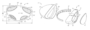
- FIG. 3 is an exploded top perspective view of a golf club head.
- FIG. 4 is a front view of a golf club head of FIG. 3 .
- FIG. 5 is a rear view of a golf club head of FIG. 3 .
- FIG. 6 is a front view of the body of a golf club head of FIG. 3 .
- FIG. 6A is a cross-sectional view taken along the line 6 A— 6 A of FIG. 6 .
- FIG. 7 is a top plan view of a golf club head illustrating the Y axis and X axis.
- FIG. 8 is a front view of a golf club head.
- FIG. 9 is a front plan view of a golf club head of the present invention illustrating the Z axis and Y axis.
- FIG. 10 is a heel side plan view of a golf club of the present invention illustrating the Z axis and X axis.
- FIG. 11 is a toe side view of the golf club head of FIG. 3 .
- FIG. 12 is a bottom plan view of the golf club head of FIG. 3 .
- FIG. 13 is an exploded top perspective of a golf club head of according to the fourth embodiment of the present invention.
- FIG. 14 is a toe side view of the golf club head of FIG. 13 .
- FIG. 15 is a heel side view of the golf club head of FIG. 13 .
- FIG. 16 is an exploded top perspective of the golf club head according to the fifth embodiment of the present invention.
- FIG. 17 is a bottom plan view of the golf club head of FIG. 16 .
- FIG. 18 is a top plan view of the golf club head of FIG. 16 .
- the present invention is directed at a face for a wood-type golf club head.
- the face or face insert is generally designated 40 .
- a preferred embodiment of the face 40 has a first thickness section 200 in the shape of a cross and a second thickness region 205 defining an interior surface 40 b of the face 40 .
- a transition portion 210 is disposed between the first thickness section 200 and the second thickness region 205 .
- the first thickness section 200 has a thickness ranging from 0.100 inch to 0.200 inch, and more preferably from 0.125 inch to 0.165 inch, and most preferably approximately 0.155 inch.
- the second thickness region 205 preferably has a thickness ranging from 0.030 inch to 0.090 inch, more preferably from 0.050 inch to 0.070 inch, and most preferably 0.060 inch.
- the transition portion 210 preferably has a thickness that tapers from the thickness of the first thickness section 200 to the thickness of the second thickness region 205 to allow for a smooth contouring interior surface 40 b as opposed to a surface with ribs.
- the first thickness section 200 has a thickness that is at least 0.025 inch greater than the thickness of the second thickness region 205 . More preferably, the first thickness section 200 has a thickness that is at least 0.050 inch greater than the thickness of the second thickness region 205 . Even more preferably, the first thickness section 200 has a thickness that is at least 0.075 inch greater than the thickness of the second thickness region 205 . Yet even more preferably, the first thickness section 200 has a thickness that is at least 0.090 inch greater than the thickness of the second thickness region 205 .
- the thickness within the first thickness section 200 is preferably uniform. However, in an alternative embodiment, the thickness within the first thickness section 200 preferably varies up to 0.020 inch, more preferably up to 0.010 inch, and most preferably up to 0.005 inch.
- the thickness within the second thickness region 205 is preferably uniform. However, in an alternative embodiment, the thickness within the second thickness region 205 preferably varies up to 0.020 inch, more preferably up to 0.010 inch, and most preferably up to 0.005 inch.
- the face or face insert 40 has a perimeter 240 with a top perimeter line 240 a and a bottom perimeter line 240 b. As shown in FIG. 1 , the face 40 preferably has a width, “Wf”, that preferably ranges from 3.50 inches to 5.00 inches, and a height, “Hf”, that preferably ranges from 1.80 inches to 2.50 inches.
- the center of the face 40 is generally designated point 300 .
- the face preferably has a mass ranging from 25 grams to 40 grams and most preferably 29 grams.
- FIG. 2 An alternative embodiment wherein the first thickness section 200 has a “X” shape is shown in FIG. 2 .
- the first thickness section 200 , the second thickness region 205 and the transition portion 210 have the same dimensions as discussed above in reference to the embodiment shown in FIG. 1 .
- the first thickness section 200 preferably includes upper extension section 350 a, lower extension section 350 b, heel extension section 350 c, toe extension section 350 d and central section 350 e.
- the second thickness region 205 preferably includes an upper toe region 330 , an upper heel region 332 , a lower heel region 334 and a lower toe region 236 .
- the first thickness section also preferably includes upper heel perimeter section 352 a, lower heel perimeter section 352 b, upper toe perimeter section 352 c and lower toe section 352 d.
- Each of the perimeter sections 352 a–d defines the perimeter of the face 40 and also partially define each of the second thickness regions 330 , 332 , 334 and 336 .
- the transition portion 210 preferably includes a transition upper toe portion 360 , a transition upper heel portion 361 , a transition lower heel portion 362 and a transition lower toe portion 363 .
- Each of the transition portions 210 has a width from 0.05 inch to 0.15 inch, more preferably from 0.07 inch to 0.11 inch, and most preferably 0.09 inch.
- the first thickness section 200 preferably includes a toe vertical section 220 , a heel vertical section 222 and a central horizontal section 224 .
- the heel vertical section 220 and the toe vertical section 222 preferable extend from the top perimeter 240 a of the face 40 to the bottom perimeter 240 b of the face 40 .
- the central horizontal section 224 extends between the toe vertical section 220 and the heel vertical section 222 , preferably about the face center 300 .
- each of the toe vertical section 220 and the heel vertical section 222 has a top end 250 a and 250 b and bottom end 252 a and 252 b.
- the width of each of the toe vertical section 220 and the heel vertical section 222 .
- the first thickness section 200 also preferably includes heel perimeter section 270 a, upper perimeter section 270 b, toe perimeter section 270 c and lower perimeter section 270 d. Each of the perimeter sections 270 a–d defines the perimeter of the face 40 and also partially define each of the second thickness regions 230 , 232 , 234 and 236 .
- the second thickness region 205 preferably includes an upper central region 230 , a lower central region 232 , a toe region 234 and a heel region 236 .
- Each of the upper central region 230 and the lower central region are larger in area than each of the toe region 234 and the heel region 236 .
- the transition portion 210 preferably includes a transition toe portion 260 , a transition heel portion 261 , a transition lower portion 262 and a transition upper portion 263 .
- Each of the transition portions 210 has a width from 0.05 inch to 0.15 inch, more preferably from 0.07 inch to 0.11 inch, and most preferably 0.09 inch.
- the face or face insert 40 is used with various golf club heads.
- a preferred embodiment of a golf club head is illustrated in FIGS. 3–10 .
- Alternative embodiments of golf club heads are illustrated in FIGS. 11–18 .
- three embodiments are illustrated, those skilled in the pertinent art will recognize from this disclosure that other embodiments of the golf club head using a face or face insert of the present invention are possible without departing from the scope and spirit of the present invention.
- a golf club head is generally designated 20 .
- the golf club head 20 has a body 22 , which includes a crown 24 , a sole 26 , a ribbon 28 , a front wall 30 and a hollow interior 34 .
- the golf club head 20 has a heel end 36 , a toe end 38 , and an aft end 37 .
- the golf club head 20 when designed as a driver, preferably has a volume from 200 cubic centimeters to 600 cubic centimeters, more preferably from 300 cubic centimeters to 500 cubic centimeters, and most preferably from 385 cubic centimeters to 475 cubic centimeters.
- the golf club head 20 preferably has a mass no more than 250 grams, and most preferably a mass of 170 to 250 grams.
- the front wall 30 has an opening 32 and preferably a recessed portion 33 .
- the face insert 40 is disposed within the opening 32 .
- the ribbon 28 of the body 22 has an aft-recess 52 located opposite of the face insert 40 , and a rear weighting member 50 is disposed within the aft-recess 52 .
- the body 22 is preferably composed of a non-metal material, preferably a composite material such as a continuous fiber pre-preg material (including thermosetting materials or a thermoplastic materials for the resin). Other materials for the body 22 include thermosetting materials or thermoplastic materials such as injectable plastics.
- the body 22 is preferably manufactured through bladder-molding, resin transfer molding, resin infusion, injection molding, compression molding, or a similar process.
- the body 22 may be composed of a lightweight metallic material, such as magnesium alloys, aluminum alloys, magnesium, aluminum, titanium, titanium alloys, or other low density metals.
- the body 22 may also be composed of a steel such as stainless steel or other steel alloys.
- the face insert 40 is attached to the body 22 over the opening 32 of the front wall 30 .
- the face insert 40 is positioned over and attached to the recessed portion 33 of the front wall 30 .
- the face insert 40 is preferably composed of a formed metal material. However, the face insert 40 may also be composed of a machined metal material, a forged metal material, a cast metal material or the like.
- the face insert 40 preferably is composed of a titanium or steel material. Titanium materials suitable for the face insert 40 include pure titanium and titanium alloys. Other metals for the face insert 40 include high strength steel alloy metals and amorphous metals.
- the exterior surface 40 a of the face insert 40 typically has a plurality of scorelines thereon, not shown.
- the face insert 40 is preferably co-molded with the body 22 or press-fitted into the opening 32 subsequent to fabrication of the body 22 .
- the body 22 is first bladder molded and then the face insert 40 is bonded to the recessed portion 33 of the front wall 30 using an adhesive.
- the adhesive is placed on the exterior surface of the recessed portion 33 .
- Such adhesives include thermosetting adhesives in a liquid or a film medium.
- the body 22 is first bladder molded and then the face insert 40 is mechanically secured to the body 22 .
- the non-metallic body 22 is preferably composed of a plurality of plies of pre-preg, typically six or seven plies (preferably ranging from three plies to twenty plies) such as disclosed in U.S. Pat. No. 6,248,025, entitled Composite Golf Head And Method Of Manufacturing, which is hereby incorporated by reference in its entirety.
- the crown 24 , the sole 26 and the ribbon 28 preferably range in thickness from 0.010 inch to 0.100 inch, more preferably from 0.025 inch to 0.070 inch, even more preferably from 0.028 inch to 0.040 inch, and most preferably have a thickness of 0.033 inch.
- the front wall 30 preferably has a thickness greater than the thickness of the crown 24 , sole 26 or ribbon 28 .
- the thickness of the front wall preferably ranges from 0.030 to 0.150 inch, more preferably from 0.050 inch to 0.100 inch, even more preferably from 0.070 inch to 0.090 inch, and most preferably the front wall 30 has a thickness of 0.080 inch.
- FIGS. 6 and 6A best illustrate the hollow interior 34 of the club head 20 .
- the recessed portion 33 of the front wall 30 encompasses the opening 32 forming a support for placement and attachment of the face insert 40 thereon.
- the front wall 30 has a shoulder 75 that preferably engages a perimeter 77 of the face insert 40 .
- a portion of the interior surface of the face insert 40 will engage the exterior surface of the recessed portion 33 of the front wall 30 .
- the thickness of the recessed portion 33 of the front wall 30 is preferably thicker than the crown 24 , the sole 26 or the ribbon 28 .
- the hosel 57 is disposed within the hollow interior 34 , and is located near the heel end 36 .
- the hosel 57 is preferably composed of an aluminum material, and preferably has a mass ranging from 3 to 10 grams, more preferably from 4 to 8 grams, and most preferably has a mass of 6 grams.
- the hosel 57 may be composed of a strong polymer material such as a urethane or ABS material.
- a shaft not shown, is disposed within the hosel 57 through a bore 55 in the crown 24 .
- a hosel insert, not shown, is preferably used to interface between the shaft and the hosel 57 . Such a hosel insert is described in U.S. Pat. No.
- the hosel 57 is preferably positioned in a hosel base 59 and extends from the sole 26 to the crown 24 .
- the hosel need not extend all the way to the side 26 and may also extend outside of the body 22 without departing from the scope and spirit of the present invention.
- the walls of the aft recess 52 are also shown in FIGS. 6 and 6 a.
- the aft recess 52 preferably extends into the hollow interior 34 forming an aft recess projection 52 a.
- the aft recess 52 is preferably defined by upper recess wall 54 , main recess wall 56 and lower recess wall 58 .
- the rear weighting member 50 is positioned within the aft recess 52 , as best shown in FIG. 3 .
- the rear weighting member 50 is preferably composed of a metal material such as steel, steel alloys, brass, tungsten, tungsten alloys, or other high density materials.
- the rear weighting member 50 is preferably co-molded with a body 22 or press-fitted within the aft recess 52 subsequent to fabrication of the body 22 .
- the body 22 is first bladder molded and then the rear weighting member 50 is bonded within the aft recess 52 using an adhesive.
- FIGS. 13–15 A second embodiment of the golf club head 20 is shown in FIGS. 13–15 , such as disclosed in U.S. Pat. No. 6,565,452, for a Multiple Material Golf Club Head with Face Insert, filed on Feb. 28, 2002, and is hereby incorporated by reference in its entirety.
- the golf club head 20 a face component 60 and an aft-body 61 .
- the face component 60 has a face cup and has a separate face insert 40 , which is placed within an opening 45 of a face cup 74 .
- the aft-body 61 has a crown portion 62 and a sole portion 64 .
- the face cup 74 has a return portion 63 that extends laterally rearward from the perimeter 73 of the front wall.
- the face insert 40 is joined to the face cup 74 of the face component 60 in a manufacturing process discussed in co-pending U.S. application Ser. No. 10/710,143, entitled Method for Processing a Golf Club Head with Cup Shaped Face Component, filed on Jun. 22, 2004, and hereby incorporated by reference in its entirety.
- the return portion 63 of the face cup preferably includes an upper lateral section 76 , a lower lateral section 78 , a heel lateral section 80 and a toe lateral section 82 .
- the return portion 63 preferably encircles the face insert 40 a full 360 degrees.
- the return portion 63 may only encompass a partial section of the face insert 40 , such as 270 degrees or 180 degrees, and may also be discontinuous.
- the upper lateral section 76 extends rearward, towards the aft-body 61 , a predetermined distance, d, to engage the crown 62 .
- the predetermined distance ranges from 0.2 inch to 1.0 inch, more preferably 0.40 inch to 0.75 inch, and most preferably 0.68 inch, as measured from the perimeter 73 of the face insert 40 to the rearward edge of the upper lateral section 76 .
- the upper lateral section 76 has a general curvature from the heel end 36 to the toe end 38 .
- the upper lateral section 76 has a length from the perimeter 73 of the face insert 40 that is preferably a minimal length near the center of the face insert 40 , and increases toward the toe end 38 and the heel end 36 .
- the minimal length may be at the heel end 36 or the toe end 38 .
- the face component 60 engages the crown portion 62 of the aft-body 61 along a substantially horizontal plane.
- the crown portion 62 has a crown undercut portion 62 a, which is placed under the return portion 63 . Such an engagement enhances the flexibility of the face insert 40 allowing for a greater coefficient of restitution.
- the crown portion 62 of the aft-body 61 and the upper lateral section 76 of the face component 60 are attached to each other as further explained below.
- the heel lateral section 80 is substantially perpendicular to the face insert 40 , and the heel lateral section 80 covers the hosel 57 before engaging an optional ribbon section 90 and a bottom section 91 of the sole portion 64 of the aft-body 61 .
- the heel lateral section 80 is attached to the sole portion 64 , both the ribbon 28 and the bottom section 91 , as explained in greater detail below.
- the heel lateral section 80 extends inward a distance, d′′′, from the perimeter 73 a distance of 0.250 inch to 1.50 inches, more preferably 0.50 inch to 1.0 inch, and most preferably 0.950 inch.
- the heel lateral section 80 preferably has a general curvature at its edge.
- the toe lateral section 82 is attached to the sole portion 64 , both the ribbon 28 and the bottom section 91 , as explained in greater detail below.
- the toe lateral section 82 extends inward a distance, d′′, from the perimeter 73 a distance of 0.250 inch to 1.50 inches, more preferably 0.75 inch to 1.30 inch, and most preferably 1.20 inch.
- the toe lateral section 82 preferably has a general curvature at its edge.
- the lower lateral section 78 of the face component 60 extends inward, toward the aft-body 61 , a predetermined distance to engage the sole portion 64 .
- the predetermined distance ranges from 0.2 inch to 1.25 inches, more preferably 0.50 inch to 1.10 inch, and most preferably 0.9 inch, as measured from the perimeter 73 of the face insert 40 to the edge of the lower lateral section 78 .
- the lower lateral section 78 has a general curvature from the heel end 36 to the toe end 38 .
- the lower lateral section 78 has a length from the perimeter 73 of the face section 72 that is preferably a minimal length near the center of the face section 40 , and increases toward the toe end 38 and the heel end 36 .
- the sole portion 64 has a sole undercut 64 a for placement under the return portion 63 .
- the sole 64 and the lower lateral section 78 , the heel lateral section 80 and the toe lateral section 82 are attached to each other as explained in greater detail below.
- the aft-body 61 is preferably composed of a non-metal material, preferably a composite material such as continuous fiber pre-preg material (including thermosetting materials or a thermoplastic materials for the resin). Other materials for the aft-body 61 include other thermosetting materials or other thermoplastic materials such as injectable plastics.
- the aft-body 61 is preferably manufactured through bladder-molding, resin transfer molding, resin infusion, injection molding, compression molding, or a similar process. Alternatively, the aft-body may be composed of a metallic material such as magnesium, titanium, stainless steel, or any other steel or titanium alloy.
- the crown portion 62 of the aft-body 61 is generally convex toward the sole portion 64 , end engages the ribbon section 90 of sole portion 64 outside of the engagement with the face member 60 .
- the crown portion 62 preferably has a thickness in the range of 0.010 to 0.100 inch, more preferably in the range of 0.025 inch to 0.070 inch, even more preferably in the range of 0.028 inch to 0.040 inch, and most preferably has a thickness of 0.033 inch.
- the sole portion 64 including the bottom section 91 and the optional ribbon section 90 which is substantially perpendicular to the bottom section 91 , preferably has a thickness in the range of 0.010 to 0.100 inch, more preferably in the range of 0.025 inch to 0.070 inch, even more preferably in the range of 0.028 inch to 0.040 inch, and most preferably has a thickness of 0.033 inch.
- the assembled face component 60 may then be attached to the aft body 61 .
- the face component 60 with an adhesive on the interior surface of the return portion 63 , is placed within a mold with a preform of the aft-body 61 for bladder molding.
- the return portion 63 is placed and fitted into the undercut portions 62 a and 64 a.
- the adhesive may be placed on the undercut portions 62 a and 64 a.
- adhesives include thermosetting adhesives in a liquid or a film medium.
- the co-molding process secures the aft-body 61 to the face component 60 .
- the aft-body 61 is first bladder molded and then is bonded to the face component 60 using an adhesive, or mechanically secured to the return portion 63 .
- FIGS. 16–18 A third embodiment of the golf club head 20 is shown in FIGS. 16–18 .
- the golf club head 20 includes a body 22 , a face 40 a weighting frame 42 , and an optional support gasket 44 .
- a more thorough description of such a golf club head 20 is set forth in U.S. Pat. No. 6,672,975, for a Golf Club Head, and assigned to the assignee of the present application, and which is hereby incorporated by reference in its entirety.
- the body 22 is preferably composed of a light weight or low-density material, preferably a non-metal material or a low-density (less than 4.5 grams per cubic centimeter) metal material, such as a polycarbonate material.
- Other materials for the body 22 include a composite material such as a continuous fiber pre-preg material (including thermosetting materials or a thermoplastic material for the resin), other thermosetting materials such as thermosetting polyurethane, or other thermoplastic materials such as polyamides, polyimides, polycarbonates, PBT (Polybutlene Terephthalate), blends of polycarbonate and polyurethane, and the like.
- the body 22 is preferably manufactured through injection molding, bladder-molding, resin transfer molding, resin infusion, compression molding, or a similar process.
- a preferred metal material for the body 22 is aluminum, tin or magnesium.
- the face 40 is attached to the frame 42 and over the opening 32 . Preferably the face 40 is positioned over and attached to the support gasket 44 .
- the face 40 is preferably composed of a formed metal material, however, the face 40 may also be composed of a machined metal material, a forged metal material, a cast metal material or the like.
- the face 40 preferably is composed of a formed titanium or steel material. Titanium materials useful for the face 40 include pure titanium and titanium alloys. Other metals for the face 40 include other high strength steel alloy metals and amorphous metals.
- the exterior surface of the face 40 typically has a plurality of scorelines thereon, not shown.
- the face 40 preferably has an elliptical shape or a trapezoidal shape.
- the face 40 preferably has a plurality of holes 46 a–d for insertion of the bolts 88 a–d there through.
- the weighting frame 42 is preferably composed of a metal material such as stainless steel, titanium alloy, aluminum, magnesium and other like metal materials. In an alternative embodiment, the weighting frame 42 is composed of a thermoplastic material.
- the frame 42 is preferably composed of four arms 86 a–d and a central body 84 . In the preferred embodiment, each of the arms 86 a–d are positioned within a corresponding groove 40 a–d of the body 22 . Each of the grooves 40 a–d are generally shaped to receive an arm 86 a–d. Each arm 86 a–d has a length sufficient to extend from the aft end 37 of the body 22 to the opening 32 .
- each arm 86 a–d is tubular with a threaded aperture at the forward end (opposite the central body 84 ) to receive a bolt for attachment of the face 40 thereto.
- the frame 42 preferably engages the face 40 at each of the corners (upper heel, lower heel, upper toe and lower toe) of the face 40 .
- the frame 42 also increases the moment of inertia of the golf club head 20 since mass is positioned at the outer extremes of the golf club head 20 .
- the attachment of the face 40 to the frame 42 provides the ability to use an amorphous metal for the face 40 and a different material for the frame 42 and the body 22 thereby eliminating problems associated with bonding amorphous metals to other metals.
- attachment through the use of bolts is preferred, other joining means may be utilized such as riveting, self taping screws, localized friction or welding, spot welding, local bonding, melt or solvent bonding, and the like.
- the frame 42 has a mass ranging from 30 grams to 90 grams, more preferably from 40 grams to 70 grams.
- the hosel 57 preferably has a mass ranging from 3 to 10 grams, more preferably from 4 to 8 grams, and most preferably has a mass of 6 grams.
- epoxy, or other like flowable materials in an amount ranging from 0.5 grams to 5 grams, may be injected into the hollow interior 50 of the golf club head 20 for selective weighting thereof.
- the depth, D, of the club head 20 from the face 40 to the after end 37 of the crown 24 preferably-ranges from 3.0 inches to 4.5 inches, and is most preferably 3.74 inches.
- the height of the club head 20 as measured while in address position from the sole 26 to the crown 24 , preferably ranges from 2.0 inches to 3.5 inches, and is most preferably 2.62 inches.
- the width, W, of the club head 20 from the toe end 38 to the heel end 36 preferably ranges from 4.0 inches to 5.5 inches, and more preferably 4.57 inches.
- the height of the face 40 preferably ranges from 1.8 inches to 2.5 inches, and is most preferably 2.08 inches.
- the width, w, of the face insert from the toe end to the heel end preferably ranges from 3.0 inches to 5.0 inches, and more preferably 3.52 inches.
- the golf club head 20 preferably has a high coefficient of restitution for greater distance of a golf ball hit with the golf club head of the present invention.
- the coefficient of restitution (also referred to herein as “COR”) is determined by the following equation:
- U 1 is the club head velocity prior to impact
- U 2 is the golf ball velocity prior to impact which is zero
- v 1 is the club head velocity just after separation of the golf ball from the face of the club head
- v 2 is the golf ball velocity just after separation of the golf ball from the face of the club head
- e is the coefficient of restitution between the golf ball and the club face.
- the values of e are limited between zero and 1.0 for systems with no energy addition.
- the coefficient of restitution, e, for a material such as a soft clay or putty would be near zero, while for a perfectly elastic material, where no energy is lost as a result of deformation, the value of e would be 1.0.
- the golf club head 20 preferably has a coefficient of restitution ranging from 0.80 to 0.94, as measured under conventional test conditions.
- the coefficient of restitution of the club head 20 of the present invention under standard USGA test conditions with a given ball preferably ranges from approximately 0.80 to 0.94, more preferably ranges from 0.82 to 0.89 and is most preferably 0.86.
- the face center 300 preferably has a COR no greater than 0.83, and the golf club head 20 preferably conforms the USGA characteristic time test.
- FIGS. 9 and 10 illustrate the axes of inertia through the center of gravity of the golf club head.
- the axes of inertia are designated X, Y and Z.
- the X axis extends from the face insert 40 through the center of gravity, CG, and to the rear of the golf club head 20 .
- the Y axis extends from the toe end 38 of the golf club head 20 through the center of gravity, CG, and to the heel end 36 of the golf club head 20 .
- the Z axis extends from the crown 24 through the center of gravity, CG, and to the sole 26 .
- the center of gravity, or center of mass, of the golf club head is a point inside of the club head determined by the vertical intersection of two or more points where the club head balances when suspended. A more thorough explanation of this definition of the center of gravity is provided in Golf Club Design, Fitting, Alteration & Repair.
- the center of gravity and the moment of inertia of a golf club head 20 are preferably measured using a test frame (X T , Y T , Z T ), and then transformed to a head frame (X H , Y H , Z H ).
- the center of gravity of a golf club head may be obtained using a center of gravity table having two weight scales thereon, as disclosed in U.S. Pat. No. 6,607,452, entitled High Moment Of Inertia Composite Golf Club, and hereby incorporated by reference in its entirety. If a shaft is present, it is removed and replaced with a hosel cube that has a multitude of faces normal to the axes of the golf club head. Given the weight of the golf club head, the scales allow one to determine the weight distribution of the golf club head when the golf club head is placed on both scales simultaneously and weighed along a particular direction, the X, Y or Z direction.
- the moment of inertia, Izz, about the Z axis for the golf club head 20 is preferably greater than 3000 g-cm 2 , and more preferably greater than 3500 g-cm 2 .
- the moment of inertia, Iyy, about the Y axis for the golf club head 20 is preferably in the range from 2000 g-cm 2 to 4000 g-cm 2 , more preferably from 2300 g-cm 2 to 3800 g-cm 2 .
- the moment of inertia, Ixx, about the X axis for the golf club head 20 is preferably in the range from 1500 g-cm 2 to 3800 g-cm 2 , more preferably from 1600 g-cm 2 to 3100 g-cm 2 .
- Table One illustrates a comparison of a golf club head with a face insert ( 40 ) of the present invention as compared to a golf club head with a face insert having a uniform thickness. Both golf club head conform to the USGA regulations for characteristic time.
- the golf club head 20 with the face insert ( 40 ) having a H-shaped first thickness section 200 has a mass that is more than 25% lighter than the uniform thickness face of the comparison golf club head while having similar CORs and characteristic times.
Landscapes
- Health & Medical Sciences (AREA)
- General Health & Medical Sciences (AREA)
- Physical Education & Sports Medicine (AREA)
- Life Sciences & Earth Sciences (AREA)
- Engineering & Computer Science (AREA)
- Wood Science & Technology (AREA)
- Golf Clubs (AREA)
Abstract
Description
wherein U1 is the club head velocity prior to impact; U2 is the golf ball velocity prior to impact which is zero; v1 is the club head velocity just after separation of the golf ball from the face of the club head; v2 is the golf ball velocity just after separation of the golf ball from the face of the club head; and e is the coefficient of restitution between the golf ball and the club face.
| Mass | Characteristic Time | Thickness | ||
| Face Design | (grams) | (μs) | COR | (inches) |
| Uniform | 42.7 | 240 | 0.828 | 0.120 |
| H-shaped | 29.0 | 240 | 0.829 | variable |
Claims (38)
Priority Applications (16)
| Application Number | Priority Date | Filing Date | Title |
|---|---|---|---|
| US10/904,332 US7101289B2 (en) | 2004-10-07 | 2004-11-04 | Golf club head with variable face thickness |
| PCT/US2005/036382 WO2006042204A1 (en) | 2004-10-07 | 2005-10-06 | Golf club head with variable face thickness |
| JP2007535881A JP2008515560A (en) | 2004-10-07 | 2005-10-06 | Golf club heads with different thickness |
| CN2005800301953A CN101014390B (en) | 2004-10-07 | 2005-10-06 | Golf club head with varying face thickness |
| US11/469,742 US7258626B2 (en) | 2004-10-07 | 2006-09-01 | Golf club head with variable face thickness |
| GB0703992A GB2431888B (en) | 2004-10-07 | 2007-03-01 | Golf club head with variable face thickness |
| US11/841,384 US7422528B2 (en) | 2004-10-07 | 2007-08-20 | Golf club head with variable face thickness |
| US11/928,318 US7448960B2 (en) | 2004-10-07 | 2007-10-30 | Golf club head with variable face thickness |
| US12/268,181 US7713140B2 (en) | 2004-10-07 | 2008-11-10 | Golf club head with variable face thickness |
| US12/487,581 US7637822B2 (en) | 2004-10-07 | 2009-06-18 | Golf club head |
| US12/636,460 US7749097B2 (en) | 2004-11-04 | 2009-12-11 | Golf club head |
| US12/711,435 US8012041B2 (en) | 2004-10-07 | 2010-02-24 | Golf club head with variable face thickness |
| US12/829,255 US7846038B2 (en) | 2004-10-07 | 2010-07-01 | Golf club head |
| US13/220,287 US8376876B2 (en) | 2004-10-07 | 2011-08-29 | Golf club head with variable face thickness |
| US13/248,817 US8696489B2 (en) | 2004-10-07 | 2011-09-29 | Golf club head with variable face thickness |
| US14/231,147 US9101809B2 (en) | 2004-10-07 | 2014-03-31 | Golf club head with variable face thickness |
Applications Claiming Priority (2)
| Application Number | Priority Date | Filing Date | Title |
|---|---|---|---|
| US10/711,825 US7137907B2 (en) | 2004-10-07 | 2004-10-07 | Golf club head with variable face thickness |
| US10/904,332 US7101289B2 (en) | 2004-10-07 | 2004-11-04 | Golf club head with variable face thickness |
Related Parent Applications (1)
| Application Number | Title | Priority Date | Filing Date |
|---|---|---|---|
| US10/711,825 Continuation-In-Part US7137907B2 (en) | 2004-10-07 | 2004-10-07 | Golf club head with variable face thickness |
Related Child Applications (3)
| Application Number | Title | Priority Date | Filing Date |
|---|---|---|---|
| US46942706A Continuation | 2004-11-04 | 2006-08-31 | |
| US11/469,742 Continuation US7258626B2 (en) | 2004-10-07 | 2006-09-01 | Golf club head with variable face thickness |
| US11/469,742 Continuation-In-Part US7258626B2 (en) | 2004-10-07 | 2006-09-01 | Golf club head with variable face thickness |
Publications (2)
| Publication Number | Publication Date |
|---|---|
| US20060079347A1 US20060079347A1 (en) | 2006-04-13 |
| US7101289B2 true US7101289B2 (en) | 2006-09-05 |
Family
ID=36148672
Family Applications (5)
| Application Number | Title | Priority Date | Filing Date |
|---|---|---|---|
| US10/904,332 Expired - Lifetime US7101289B2 (en) | 2004-10-07 | 2004-11-04 | Golf club head with variable face thickness |
| US11/469,742 Expired - Lifetime US7258626B2 (en) | 2004-10-07 | 2006-09-01 | Golf club head with variable face thickness |
| US11/841,384 Expired - Lifetime US7422528B2 (en) | 2004-10-07 | 2007-08-20 | Golf club head with variable face thickness |
| US11/928,318 Expired - Lifetime US7448960B2 (en) | 2004-10-07 | 2007-10-30 | Golf club head with variable face thickness |
| US12/268,181 Expired - Lifetime US7713140B2 (en) | 2004-10-07 | 2008-11-10 | Golf club head with variable face thickness |
Family Applications After (4)
| Application Number | Title | Priority Date | Filing Date |
|---|---|---|---|
| US11/469,742 Expired - Lifetime US7258626B2 (en) | 2004-10-07 | 2006-09-01 | Golf club head with variable face thickness |
| US11/841,384 Expired - Lifetime US7422528B2 (en) | 2004-10-07 | 2007-08-20 | Golf club head with variable face thickness |
| US11/928,318 Expired - Lifetime US7448960B2 (en) | 2004-10-07 | 2007-10-30 | Golf club head with variable face thickness |
| US12/268,181 Expired - Lifetime US7713140B2 (en) | 2004-10-07 | 2008-11-10 | Golf club head with variable face thickness |
Country Status (4)
| Country | Link |
|---|---|
| US (5) | US7101289B2 (en) |
| JP (1) | JP2008515560A (en) |
| GB (1) | GB2431888B (en) |
| WO (1) | WO2006042204A1 (en) |
Cited By (83)
| Publication number | Priority date | Publication date | Assignee | Title |
|---|---|---|---|---|
| US20060194644A1 (en) * | 2005-02-25 | 2006-08-31 | Sri Sports Limited | Golf club head |
| US20070004536A1 (en) * | 2004-10-07 | 2007-01-04 | Gibbs Evan D | Golf Club Head with Variable Face Thickness |
| US20070026962A1 (en) * | 2004-06-25 | 2007-02-01 | Galloway J A | Golf Club Head |
| US20070207877A1 (en) * | 2006-03-03 | 2007-09-06 | Sri Sports Limited | Golf club head |
| US20080051218A1 (en) * | 2006-12-22 | 2008-02-28 | Roger Cleveland Golf Co., Inc. | Golf club head |
| US20080096689A1 (en) * | 2006-10-19 | 2008-04-24 | Sri Sports Limited | Wood-type hollow golf club head |
| USD567891S1 (en) | 2007-12-19 | 2008-04-29 | Karsten Manufacturing Corporation | Golf club head |
| US20080113827A1 (en) * | 2006-11-14 | 2008-05-15 | Origin Inc. | Plastic golf club head |
| US20080139334A1 (en) * | 2006-12-06 | 2008-06-12 | Taylor Made Golf Company, Inc. | Golf clubs and club-heads comprising a face plate having a central recess and flanking recesses |
| USD572791S1 (en) | 2008-02-07 | 2008-07-08 | Karsten Manufacturing Corporation | Golf club head |
| US20080171612A1 (en) * | 2007-01-12 | 2008-07-17 | Karsten Manufacturing Corporation | Golf Club Heads With One or More Indented Inserts and Methods to Manufacture Golf Club Heads |
| US7413520B1 (en) * | 2007-03-09 | 2008-08-19 | Callaway Golf Company | Golf club head with high moment of inertia |
| USD583432S1 (en) | 2007-12-19 | 2008-12-23 | Karsten Manufacturing Corporation | Golf club head |
| US20090017937A1 (en) * | 2007-07-13 | 2009-01-15 | Sri Sports Limited | Wood-type golf club head |
| USD588217S1 (en) | 2008-02-07 | 2009-03-10 | Karsten Manufacturing Corporation | Golf club head |
| USD588659S1 (en) | 2008-02-07 | 2009-03-17 | Karsten Manufacturing Corporation | Golf club head |
| US20090088272A1 (en) * | 2005-01-03 | 2009-04-02 | Callaway Golf Company | Golf club head |
| US7549934B2 (en) * | 2005-09-07 | 2009-06-23 | Acushnet Company | Metal wood club with improved hitting face |
| US20090163294A1 (en) * | 2007-12-19 | 2009-06-25 | Callaway Golf Company | Driver with deep aft cavity |
| US20090181789A1 (en) * | 2008-01-10 | 2009-07-16 | Tim Reed | Fairway wood type golf club |
| US20100048316A1 (en) * | 2008-01-10 | 2010-02-25 | Justin Honea | Fairway wood type golf club |
| US7704162B2 (en) * | 2000-04-18 | 2010-04-27 | Acushnet Company | Metal wood club with improved hitting face |
| US20100178997A1 (en) * | 2004-10-07 | 2010-07-15 | Callaway Golf Company | Golf club head with variable face thickness |
| US20110218053A1 (en) * | 2010-03-05 | 2011-09-08 | Callaway Golf Company | Golf club head |
| US20120021849A1 (en) * | 2004-10-07 | 2012-01-26 | Callaway Golf Company | Golf club head with variable face thickness |
| US20120108359A1 (en) * | 2010-11-02 | 2012-05-03 | Hiroshi Abe | Golf club |
| US8177659B1 (en) | 2010-12-10 | 2012-05-15 | Callaway Golf Company | Golf club head with improved aerodynamic characteristics |
| US8197358B1 (en) | 2009-12-16 | 2012-06-12 | Callaway Golf Company | Golf club head with composite weight port |
| US20120157227A1 (en) * | 2010-12-20 | 2012-06-21 | John Morin | Striking face of a golf club head |
| US8235844B2 (en) | 2010-06-01 | 2012-08-07 | Adams Golf Ip, Lp | Hollow golf club head |
| US8485919B2 (en) | 2009-12-16 | 2013-07-16 | Callaway Golf Company | Golf club head with composite weight port |
| US8491416B1 (en) | 2010-08-20 | 2013-07-23 | Callaway Golf Company | Golf club head |
| US8540588B2 (en) | 2009-12-16 | 2013-09-24 | Bradley C. Rice | Golf club head with composite weight port |
| US8585510B1 (en) * | 2010-08-30 | 2013-11-19 | Callaway Golf Company | Golf club head with improved aerodynamic characteristics |
| US8821312B2 (en) | 2010-06-01 | 2014-09-02 | Taylor Made Golf Company, Inc. | Golf club head having a stress reducing feature with aperture |
| US8827831B2 (en) | 2010-06-01 | 2014-09-09 | Taylor Made Golf Company, Inc. | Golf club head having a stress reducing feature |
| US8956246B2 (en) | 2010-12-20 | 2015-02-17 | Acushnet Company | Striking face of a golf club head |
| US20150105177A1 (en) * | 2010-12-28 | 2015-04-16 | Taylor Made Golf Company, Inc. | Fairway wood center of gravity projection |
| US9089749B2 (en) | 2010-06-01 | 2015-07-28 | Taylor Made Golf Company, Inc. | Golf club head having a shielded stress reducing feature |
| US9162115B1 (en) | 2009-10-27 | 2015-10-20 | Taylor Made Golf Company, Inc. | Golf club head |
| US9211451B1 (en) * | 2012-04-19 | 2015-12-15 | Callaway Golf Company | Weighted golf club head |
| US9545545B2 (en) | 2013-12-31 | 2017-01-17 | Fusheng Precision Co., Ltd. | Method for manufacturing a high-strength steel wooden golf head |
| US9586105B1 (en) * | 2012-04-19 | 2017-03-07 | Callaway Golf Company | Weighted golf club head |
| US9669270B2 (en) | 2014-08-26 | 2017-06-06 | Parsons Xtreme Golf, LLC | Golf club heads and methods to manufacture golf club heads |
| US9682295B1 (en) * | 2016-01-18 | 2017-06-20 | Callaway Golf Company | Multiple-material golf club head with scarf joint |
| US20170252612A1 (en) * | 2009-11-11 | 2017-09-07 | Acushnet Company | Golf club head with replaceable face |
| US9908011B2 (en) * | 2010-11-30 | 2018-03-06 | Nike, Inc. | Golf club heads or other ball striking devices having distributed impact response |
| US10150017B2 (en) | 2012-05-31 | 2018-12-11 | Nike, Inc. | Golf club head or other ball striking device having impact-influencing body features |
| US10532257B2 (en) | 2014-08-26 | 2020-01-14 | Parsons Xtreme Golf, LLC | Golf club heads and methods to manufacture golf club heads |
| US10610747B2 (en) | 2004-11-08 | 2020-04-07 | Taylor Made Golf Company, Inc. | Golf club |
| US10806977B2 (en) | 2018-01-19 | 2020-10-20 | Karsten Manufacturing Corporation | Golf club heads comprising a thermoplastic composite material |
| US10940374B2 (en) | 2016-05-27 | 2021-03-09 | Karsten Manufacturing Corporation | Mixed material golf club head |
| US10940373B2 (en) | 2016-05-27 | 2021-03-09 | Karsten Manufacturing Corporation | Mixed material golf club head |
| US11000742B2 (en) | 2014-08-26 | 2021-05-11 | Parsons Xtreme Golf, LLC | Golf club heads and methods to manufacture golf club heads |
| US11110325B2 (en) | 2018-01-19 | 2021-09-07 | Karsten Manufacturing Corporation | Mixed material golf club head |
| US11278775B2 (en) | 2016-05-27 | 2022-03-22 | Karsten Manufacturing Corporation | Mixed material golf club head |
| US11406880B1 (en) | 2020-10-05 | 2022-08-09 | Cobra Golf Incorporated | Systems and methods for a variable thickness club head |
| US11433285B1 (en) | 2021-03-09 | 2022-09-06 | Acushnet Company | Golf club head with hosel hole cover |
| US11484756B2 (en) | 2017-01-10 | 2022-11-01 | Parsons Xtreme Golf, LLC | Golf club heads and methods to manufacture golf club heads |
| US11617925B2 (en) | 2019-03-11 | 2023-04-04 | Parsons Xtreme Golf, LLC | Golf club heads and methods to manufacture golf club heads |
| US11617926B2 (en) | 2021-03-09 | 2023-04-04 | Acushnet Company | Golf club head with hosel hole cover |
| US11654338B2 (en) | 2017-01-10 | 2023-05-23 | Parsons Xtreme Golf, LLC | Golf club heads and methods to manufacture golf club heads |
| US11673035B2 (en) * | 2009-01-21 | 2023-06-13 | Taylor Made Golf Company, Inc. | Golf club head |
| US11697050B2 (en) | 2014-08-26 | 2023-07-11 | Parsons Xtreme Golf, LLC | Golf club heads and methods to manufacture golf club heads |
| US11707655B2 (en) | 2018-02-12 | 2023-07-25 | Parsons Xtreme Golf, LLC | Golf club heads and methods to manufacture golf club heads |
| US11745067B2 (en) | 2017-03-29 | 2023-09-05 | Parsons Xtreme Golf, LLC | Golf club heads and methods to manufacture golf club heads |
| US11771962B2 (en) | 2020-08-21 | 2023-10-03 | Wilson Sporting Goods Co. | Faceplate of a golf club head |
| US11806589B2 (en) | 2019-03-11 | 2023-11-07 | Parsons Xtreme Golf, LLC | Golf club heads and methods to manufacture golf club heads |
| US11819743B2 (en) | 2016-05-27 | 2023-11-21 | Karsten Manufacturing Corporation | Mixed material golf club head |
| US11839799B2 (en) | 2019-01-02 | 2023-12-12 | Parsons Xtreme Golf, LLC | Golf club heads and methods to manufacture golf club heads |
| US11839800B2 (en) | 2018-02-12 | 2023-12-12 | Parsons Xtreme Golf, LLC | Golf club heads and methods to manufacture golf club heads |
| US11839798B2 (en) | 2019-03-11 | 2023-12-12 | Parsons Xtreme Golf, LLC | Golf club heads and methods to manufacture golf club heads |
| US11938385B1 (en) | 2018-02-12 | 2024-03-26 | Parsons Xtreme Golf, LLC | Golf club heads and methods to manufacture golf club heads |
| US11969632B2 (en) | 2016-05-27 | 2024-04-30 | Karsten Manufacturing Corporation | Mixed material golf club head |
| US12109464B2 (en) | 2018-02-12 | 2024-10-08 | Parsons Xtreme Golf, LLC | Golf club heads and methods to manufacture golf club heads |
| US12121782B2 (en) | 2014-08-26 | 2024-10-22 | Parsons Xtreme Golf, LLC | Golf club heads and methods to manufacture golf club heads |
| US12179072B2 (en) | 2014-08-26 | 2024-12-31 | Parsons Extreme Golf, Llc | Golf club heads and methods to manufacture golf club heads |
| US12194351B1 (en) | 2021-11-08 | 2025-01-14 | Parsons Xtreme Golf, LLC | Golf club heads and methods to manufacture golf club heads |
| US12214265B1 (en) | 2020-12-04 | 2025-02-04 | Cobra Golf Incorporated | Golf club face plate having correlated characteristic time measurement map |
| US12233318B2 (en) | 2020-12-29 | 2025-02-25 | Taylor Made Golf Company, Inc. | Golf club heads |
| US12290725B2 (en) | 2017-01-10 | 2025-05-06 | Parsons Xtreme Golf, LLC | Golf club heads and methods to manufacture golf club heads |
| US12324967B2 (en) | 2018-02-12 | 2025-06-10 | Parsons Xtreme Golf, LLC | Golf club heads and methods to manufacture golf club heads |
| US12434112B2 (en) | 2019-03-11 | 2025-10-07 | Parsons Xtreme Golf, LLC | Golf club heads and methods to manufacture golf club heads |
Families Citing this family (101)
| Publication number | Priority date | Publication date | Assignee | Title |
|---|---|---|---|---|
| US7731603B2 (en) * | 2007-09-27 | 2010-06-08 | Taylor Made Golf Company, Inc. | Golf club head |
| JP3974055B2 (en) * | 2003-03-07 | 2007-09-12 | Sriスポーツ株式会社 | Golf club head |
| EP1624942A1 (en) * | 2003-04-11 | 2006-02-15 | Dewhurst Solution, LLC | Golf club head with force transfer system |
| US7651414B2 (en) * | 2004-10-13 | 2010-01-26 | Roger Cleveland Golf Company, Inc. | Golf club head having a displaced crown portion |
| US7559851B2 (en) * | 2005-01-03 | 2009-07-14 | Callaway Golf Company | Golf club with high moment of inertia |
| US9643065B2 (en) | 2005-05-10 | 2017-05-09 | Nike, Inc. | Golf clubs and golf club heads |
| US8439769B2 (en) * | 2005-09-07 | 2013-05-14 | Acushnet Company | Metal wood club with improved hitting face |
| US20070298903A1 (en) * | 2006-06-22 | 2007-12-27 | Nike, Inc. | Golf clubs and golf club heads |
| US8870682B2 (en) | 2006-07-21 | 2014-10-28 | Cobra Golf Incorporated | Multi-material golf club head |
| US7922604B2 (en) | 2006-07-21 | 2011-04-12 | Cobra Golf Incorporated | Multi-material golf club head |
| JP4965385B2 (en) * | 2006-07-21 | 2012-07-04 | コブラ ゴルフ インコーポレイテッド | Multi-material golf club head |
| US9586104B2 (en) | 2006-07-21 | 2017-03-07 | Cobra Golf Incorporated | Multi-material golf club head |
| US7931546B2 (en) * | 2006-10-25 | 2011-04-26 | Acushnet Company | Metal wood club with improved moment of inertia |
| US8419569B2 (en) | 2006-10-25 | 2013-04-16 | Acushnet Company | Metal wood club with improved moment of inertia |
| US9320949B2 (en) | 2006-10-25 | 2016-04-26 | Acushnet Company | Golf club head with flexure |
| US9636559B2 (en) | 2006-10-25 | 2017-05-02 | Acushnet Company | Golf club head with depression |
| US9498688B2 (en) | 2006-10-25 | 2016-11-22 | Acushnet Company | Golf club head with stiffening member |
| US20080113825A1 (en) * | 2006-11-10 | 2008-05-15 | K.K. Endo Seisakusho | Golf club head |
| TWM313006U (en) * | 2006-12-11 | 2007-06-01 | Fu Sheng Ind Co Ltd | Strengthened structure for lightweight cover of golf club head |
| JP4944830B2 (en) * | 2008-04-03 | 2012-06-06 | Sriスポーツ株式会社 | Golf club head |
| US20090270199A1 (en) * | 2008-04-24 | 2009-10-29 | Yung-Hsiung Chen | Golf club head |
| JP5237688B2 (en) * | 2008-05-12 | 2013-07-17 | ダンロップスポーツ株式会社 | Golf club head |
| JP5349006B2 (en) * | 2008-10-29 | 2013-11-20 | ブリヂストンスポーツ株式会社 | Golf club head |
| US7896753B2 (en) * | 2008-10-31 | 2011-03-01 | Nike, Inc. | Wrapping element for a golf club |
| US8070623B2 (en) * | 2008-11-21 | 2011-12-06 | Nike, Inc. | Golf club head or other ball striking device having stiffened face portion |
| US20100139073A1 (en) * | 2008-12-05 | 2010-06-10 | Callaway Golf Company | Method of producing golf club wood head using folded metal strip or sheet |
| US8337327B2 (en) * | 2008-12-15 | 2012-12-25 | Callaway Golf Company | Fairway wood type golf club head |
| US20100181368A1 (en) * | 2008-12-24 | 2010-07-22 | Callaway Golf Company | Golf club assembly using ultrasonic welding |
| US7819753B1 (en) | 2008-12-24 | 2010-10-26 | Callaway Golf Company | Aerodynamic control surface on a golf club for training purposes |
| US9795845B2 (en) | 2009-01-20 | 2017-10-24 | Karsten Manufacturing Corporation | Golf club and golf club head structures |
| US9149693B2 (en) | 2009-01-20 | 2015-10-06 | Nike, Inc. | Golf club and golf club head structures |
| US9192831B2 (en) | 2009-01-20 | 2015-11-24 | Nike, Inc. | Golf club and golf club head structures |
| US8668595B2 (en) | 2011-04-28 | 2014-03-11 | Nike, Inc. | Golf clubs and golf club heads |
| JP5451187B2 (en) * | 2009-06-02 | 2014-03-26 | ブリヂストンスポーツ株式会社 | Golf club head |
| US8292753B1 (en) | 2009-06-03 | 2012-10-23 | Callaway Golf Company | Device to measure the motion of a golf club through measurement of the shaft using wave radar |
| US8062145B1 (en) | 2009-06-04 | 2011-11-22 | Callaway Golf Company | Device to measure the motion of a golf club |
| US7892102B1 (en) | 2009-06-04 | 2011-02-22 | Callaway Golf Company | Device to measure the motion of a golf club |
| US20110028230A1 (en) * | 2009-07-31 | 2011-02-03 | Callaway Golf Company | Method and system for shot tracking |
| US8118687B1 (en) | 2009-06-12 | 2012-02-21 | Callaway Golf Company | Device to measure the motion of a golf club |
| US8142302B2 (en) * | 2009-07-30 | 2012-03-27 | Callaway Golf Company | Method and system for shot tracking |
| US8529370B1 (en) | 2009-09-24 | 2013-09-10 | Callaway Golf Company | Golf club head with a compression-molded, thin-walled aft-body |
| US20110077102A1 (en) * | 2009-09-29 | 2011-03-31 | Callaway Golf Company | Golf club body fabricated with long carbon fiber material |
| US20110081986A1 (en) * | 2009-10-01 | 2011-04-07 | Nike, Inc. | Golf clubs and golf club heads having a removable mass ring |
| US8715107B2 (en) * | 2009-11-04 | 2014-05-06 | Sri Sports Limited | Golf club head |
| US20110143849A1 (en) * | 2009-12-14 | 2011-06-16 | Callaway Golf Company | Method and system for shot tracking |
| US20110143848A1 (en) * | 2009-12-16 | 2011-06-16 | Callaway Golf Company | Method and system for shot tracking |
| US8430762B2 (en) * | 2009-12-16 | 2013-04-30 | Callaway Golf Company | Method and system for shot tracking |
| US20110151986A1 (en) * | 2009-12-17 | 2011-06-23 | Callaway Golf Company | Method and system for shot tracking |
| JP2011136043A (en) * | 2009-12-28 | 2011-07-14 | Bridgestone Sports Co Ltd | Golf club head |
| US7946926B1 (en) * | 2010-02-01 | 2011-05-24 | Callaway Golf Company | Shot tracking |
| US8516675B2 (en) * | 2010-02-10 | 2013-08-27 | Callaway Golf Company | Method of forming a golf club head with improved aerodynamic characteristics |
| US8574096B2 (en) * | 2010-02-10 | 2013-11-05 | Callaway Golf Company | Golf club head with improved aerodynamic characteristics |
| US8646163B2 (en) | 2010-02-10 | 2014-02-11 | Callaway Golf Company | Method of forming a golf club head with improved aerodynamic characteristics |
| US8510927B2 (en) * | 2010-02-10 | 2013-08-20 | Callaway Golf Company | Method of forming a golf club head with improved aerodynamic charcteristics |
| US8562455B2 (en) * | 2010-02-10 | 2013-10-22 | Callaway Golf Company | Method of forming a golf club head with improved aerodynamic characteristics |
| JP5421147B2 (en) * | 2010-02-15 | 2014-02-19 | ブリヂストンスポーツ株式会社 | Golf club head |
| US8192293B2 (en) | 2010-03-09 | 2012-06-05 | Callaway Golf Company | Method and system for shot tracking |
| US7883428B1 (en) | 2010-04-27 | 2011-02-08 | Callaway Golf Company | Shot tracking |
| US7927225B1 (en) | 2010-05-14 | 2011-04-19 | Callaway Golf Company | Device for shot tracking |
| US7915865B1 (en) | 2010-04-28 | 2011-03-29 | Callaway Golf Company | Method and system for shot tracking |
| US8241142B2 (en) | 2010-07-16 | 2012-08-14 | Callaway Golf Company | Golf club head with improved aerodynamic characteristics |
| US8446255B2 (en) | 2010-11-19 | 2013-05-21 | Callaway Golf Company | Circuit for transmitting a RFID signal |
| US9687705B2 (en) | 2010-11-30 | 2017-06-27 | Nike, Inc. | Golf club head or other ball striking device having impact-influencing body features |
| US8568247B1 (en) | 2010-12-10 | 2013-10-29 | Callaway Golf Company | Golf club head with improved aerodynamic characteristics |
| US9707457B2 (en) | 2010-12-28 | 2017-07-18 | Taylor Made Golf Company, Inc. | Golf club |
| US8888607B2 (en) | 2010-12-28 | 2014-11-18 | Taylor Made Golf Company, Inc. | Fairway wood center of gravity projection |
| US10639524B2 (en) | 2010-12-28 | 2020-05-05 | Taylor Made Golf Company, Inc. | Golf club head |
| US9409076B2 (en) | 2011-04-28 | 2016-08-09 | Nike, Inc. | Golf clubs and golf club heads |
| US9409073B2 (en) | 2011-04-28 | 2016-08-09 | Nike, Inc. | Golf clubs and golf club heads |
| US9375624B2 (en) | 2011-04-28 | 2016-06-28 | Nike, Inc. | Golf clubs and golf club heads |
| US9433845B2 (en) | 2011-04-28 | 2016-09-06 | Nike, Inc. | Golf clubs and golf club heads |
| US9433844B2 (en) | 2011-04-28 | 2016-09-06 | Nike, Inc. | Golf clubs and golf club heads |
| JP6209161B2 (en) | 2011-08-23 | 2017-10-04 | ナイキ イノベイト セー. フェー. | Golf club head having air gap |
| US8663027B2 (en) * | 2011-09-21 | 2014-03-04 | Karsten Manufacturing Corporation | Golf club face plates with internal cell lattices and related methods |
| US11925839B2 (en) * | 2011-09-21 | 2024-03-12 | Karsten Manufacturing Corporation | Golf club face plates with internal cell lattices and related methods |
| US9220959B2 (en) | 2012-08-02 | 2015-12-29 | Cobra Golf Incorporated | Golf club with cellular mass distribution |
| US11617927B2 (en) * | 2012-09-18 | 2023-04-04 | Taylor Made Golf Company, Inc. | Golf club head |
| US8992346B1 (en) | 2012-12-03 | 2015-03-31 | Callaway Golf Company | Method and system for swing analysis |
| US9168435B1 (en) | 2014-06-20 | 2015-10-27 | Nike, Inc. | Golf club head or other ball striking device having impact-influencing body features |
| US11779819B2 (en) * | 2014-08-26 | 2023-10-10 | Parsons Xtreme Golf, LLC | Golf club heads and methods to manufacture golf club heads |
| US9526956B2 (en) | 2014-09-05 | 2016-12-27 | Acushnet Company | Golf club head |
| US9597561B1 (en) * | 2015-06-30 | 2017-03-21 | Callaway Golf Company | Golf club head having face stress-reduction features |
| US10245479B2 (en) | 2015-11-18 | 2019-04-02 | Acushnet Company | Multi-material golf club head |
| US10350464B2 (en) | 2015-11-18 | 2019-07-16 | Acushnet Company | Multi-material golf club head |
| US10343030B2 (en) | 2015-11-18 | 2019-07-09 | Acushnet Company | Multi-material golf club head |
| US10434380B2 (en) | 2015-11-18 | 2019-10-08 | Acushnet Company | Multi-material golf club head |
| US10232230B2 (en) | 2015-11-18 | 2019-03-19 | Acushnet Company | Multi-material golf club head |
| US10086239B2 (en) | 2015-11-18 | 2018-10-02 | Acushnet Company | Multi-material golf club head |
| US10569143B2 (en) | 2015-11-18 | 2020-02-25 | Acushnet Company | Multi-material golf club head |
| US10065084B2 (en) | 2015-11-18 | 2018-09-04 | Acushnet Company | Multi-material golf club head |
| US10195497B1 (en) | 2016-09-13 | 2019-02-05 | Taylor Made Golf Company, Inc | Oversized golf club head and golf club |
| US10207160B2 (en) * | 2016-12-30 | 2019-02-19 | Taylor Made Golf Company, Inc. | Golf club heads |
| US20180345099A1 (en) | 2017-06-05 | 2018-12-06 | Taylor Made Golf Company, Inc. | Golf club heads |
| US10653926B2 (en) | 2018-07-23 | 2020-05-19 | Taylor Made Golf Company, Inc. | Golf club heads |
| JP6645569B1 (en) * | 2018-12-27 | 2020-02-14 | 住友ゴム工業株式会社 | Golf club head |
| US11766592B2 (en) * | 2020-10-27 | 2023-09-26 | Acushnet Company | Multi-material golf club head |
| US11759685B2 (en) | 2020-12-28 | 2023-09-19 | Taylor Made Golf Company, Inc. | Golf club heads |
| US11406881B2 (en) | 2020-12-28 | 2022-08-09 | Taylor Made Golf Company, Inc. | Golf club heads |
| JP7669711B2 (en) * | 2021-02-05 | 2025-04-30 | 住友ゴム工業株式会社 | Golf Club Head |
| US11679313B2 (en) | 2021-09-24 | 2023-06-20 | Acushnet Company | Golf club head |
| US20230338786A1 (en) | 2022-04-20 | 2023-10-26 | Acushnet Company | Multi-material golf club head |
Citations (11)
| Publication number | Priority date | Publication date | Assignee | Title |
|---|---|---|---|---|
| US2087685A (en) * | 1935-02-16 | 1937-07-20 | William A Blair | Golf club |
| US3814437A (en) * | 1973-01-30 | 1974-06-04 | S Winquist | Symbolically reinforced golf club head |
| US4919430A (en) * | 1987-03-12 | 1990-04-24 | Antonious A J | Golf club head |
| US5401021A (en) * | 1993-10-22 | 1995-03-28 | Vardon Golf Company, Inc. | Set of golf club irons with enlarged faces |
| US5595552A (en) * | 1995-12-15 | 1997-01-21 | Karsten Manufacturing Corp. | Golf club head with tuning and vibration control means |
| US5643108A (en) * | 1995-08-31 | 1997-07-01 | National Science Council | Structure for golf club head and the method of its manufacture |
| US5830084A (en) * | 1996-10-23 | 1998-11-03 | Callaway Golf Company | Contoured golf club face |
| US5971868A (en) * | 1996-10-23 | 1999-10-26 | Callaway Golf Company | Contoured back surface of golf club face |
| US6800039B1 (en) * | 2003-03-11 | 2004-10-05 | Wen-Cheng Tseng | Golf club striking face with varied thickness distribution |
| US6926618B2 (en) * | 2003-05-19 | 2005-08-09 | Karsten Manufacturing Corporation | Golf club with diagonally reinforced contoured front wall |
| US6960142B2 (en) * | 2000-04-18 | 2005-11-01 | Acushnet Company | Golf club head with a high coefficient of restitution |
Family Cites Families (20)
| Publication number | Priority date | Publication date | Assignee | Title |
|---|---|---|---|---|
| US4681321A (en) * | 1986-01-29 | 1987-07-21 | Chen Chin Chi | Golf club head |
| US4932658A (en) * | 1987-03-12 | 1990-06-12 | Antonious A J | Golf club head |
| FR2689407A1 (en) * | 1992-04-01 | 1993-10-08 | Taylor Made Golf Co | Golf club head composed of a plastic hollow body and a sealing element. |
| US5295689A (en) * | 1993-01-11 | 1994-03-22 | S2 Golf Inc. | Golf club head |
| US5451058A (en) * | 1994-05-05 | 1995-09-19 | Price; Parker G. | Low center of gravity golf club |
| US5839975A (en) * | 1997-01-22 | 1998-11-24 | Black Rock Golf Corporation | Arch reinforced golf club head |
| JP3315618B2 (en) * | 1997-03-18 | 2002-08-19 | 有限会社マークス クリエイティブ クラフト | Golf club head |
| US6059669A (en) * | 1998-05-04 | 2000-05-09 | Edizone, Lc | Golf club head having performance-enhancing structure |
| GB9909135D0 (en) | 1999-04-22 | 1999-06-16 | Univ Wales Medicine | Cystic fibrosis medicaments |
| US6558271B1 (en) * | 2000-01-18 | 2003-05-06 | Taylor Made Golf Company, Inc. | Golf club head skeletal support structure |
| US20020169035A1 (en) * | 2001-05-09 | 2002-11-14 | Clara Liu | Structure for the club head of a wooden club |
| JP2003180887A (en) * | 2001-12-21 | 2003-07-02 | Shimano Inc | Golf club head |
| JP2003290398A (en) * | 2002-01-29 | 2003-10-14 | Yonex Co Ltd | Golf club head |
| US6659885B1 (en) * | 2002-02-01 | 2003-12-09 | Panda Golf, Inc. | Golf club head |
| JP2004041681A (en) * | 2002-07-12 | 2004-02-12 | Callaway Golf Co | Golf club head with metal hit plate insert |
| US6672975B1 (en) * | 2003-02-06 | 2004-01-06 | Callaway Golf Company | Golf club head |
| US7101289B2 (en) * | 2004-10-07 | 2006-09-05 | Callaway Golf Company | Golf club head with variable face thickness |
| US7137907B2 (en) * | 2004-10-07 | 2006-11-21 | Callaway Golf Company | Golf club head with variable face thickness |
| DE102005037857A1 (en) * | 2005-08-10 | 2007-02-15 | Thielen Feinmechanik Gmbh & Co. Fertigungs Kg | golf club |
| US7632195B2 (en) * | 2005-08-15 | 2009-12-15 | Acushnet Company | Golf club head with low density crown |
-
2004
- 2004-11-04 US US10/904,332 patent/US7101289B2/en not_active Expired - Lifetime
-
2005
- 2005-10-06 WO PCT/US2005/036382 patent/WO2006042204A1/en not_active Ceased
- 2005-10-06 JP JP2007535881A patent/JP2008515560A/en active Pending
-
2006
- 2006-09-01 US US11/469,742 patent/US7258626B2/en not_active Expired - Lifetime
-
2007
- 2007-03-01 GB GB0703992A patent/GB2431888B/en not_active Expired - Fee Related
- 2007-08-20 US US11/841,384 patent/US7422528B2/en not_active Expired - Lifetime
- 2007-10-30 US US11/928,318 patent/US7448960B2/en not_active Expired - Lifetime
-
2008
- 2008-11-10 US US12/268,181 patent/US7713140B2/en not_active Expired - Lifetime
Patent Citations (11)
| Publication number | Priority date | Publication date | Assignee | Title |
|---|---|---|---|---|
| US2087685A (en) * | 1935-02-16 | 1937-07-20 | William A Blair | Golf club |
| US3814437A (en) * | 1973-01-30 | 1974-06-04 | S Winquist | Symbolically reinforced golf club head |
| US4919430A (en) * | 1987-03-12 | 1990-04-24 | Antonious A J | Golf club head |
| US5401021A (en) * | 1993-10-22 | 1995-03-28 | Vardon Golf Company, Inc. | Set of golf club irons with enlarged faces |
| US5643108A (en) * | 1995-08-31 | 1997-07-01 | National Science Council | Structure for golf club head and the method of its manufacture |
| US5595552A (en) * | 1995-12-15 | 1997-01-21 | Karsten Manufacturing Corp. | Golf club head with tuning and vibration control means |
| US5830084A (en) * | 1996-10-23 | 1998-11-03 | Callaway Golf Company | Contoured golf club face |
| US5971868A (en) * | 1996-10-23 | 1999-10-26 | Callaway Golf Company | Contoured back surface of golf club face |
| US6960142B2 (en) * | 2000-04-18 | 2005-11-01 | Acushnet Company | Golf club head with a high coefficient of restitution |
| US6800039B1 (en) * | 2003-03-11 | 2004-10-05 | Wen-Cheng Tseng | Golf club striking face with varied thickness distribution |
| US6926618B2 (en) * | 2003-05-19 | 2005-08-09 | Karsten Manufacturing Corporation | Golf club with diagonally reinforced contoured front wall |
Cited By (230)
| Publication number | Priority date | Publication date | Assignee | Title |
|---|---|---|---|---|
| US7704162B2 (en) * | 2000-04-18 | 2010-04-27 | Acushnet Company | Metal wood club with improved hitting face |
| US20080139337A1 (en) * | 2004-06-25 | 2008-06-12 | Callaway Golf Company | Golf club head |
| US7503854B2 (en) * | 2004-06-25 | 2009-03-17 | Callaway Golf Company | Golf club head |
| US20070026962A1 (en) * | 2004-06-25 | 2007-02-01 | Galloway J A | Golf Club Head |
| US20090176599A1 (en) * | 2004-06-25 | 2009-07-09 | Callaway Golf Company | Golf club head |
| US7674190B2 (en) | 2004-06-25 | 2010-03-09 | Callaway Golf Company | Golf club head |
| US20100151961A1 (en) * | 2004-06-25 | 2010-06-17 | Callaway Golf Company | Golf club head |
| US7811181B2 (en) | 2004-06-25 | 2010-10-12 | Callaway Golf Company | Golf club head |
| US7416496B2 (en) | 2004-06-25 | 2008-08-26 | Callaway Golf Company | Gold club head |
| US20110028239A1 (en) * | 2004-06-25 | 2011-02-03 | Callaway Golf Company | Golf club head |
| US7938742B2 (en) | 2004-06-25 | 2011-05-10 | Callaway Golf Company | Golf club head |
| US8696489B2 (en) * | 2004-10-07 | 2014-04-15 | Callaway Gold Company | Golf club head with variable face thickness |
| US20070287553A1 (en) * | 2004-10-07 | 2007-12-13 | Callaway Golf Company | Golf club head with variable face thickness |
| US20110312438A1 (en) * | 2004-10-07 | 2011-12-22 | Callaway Golf Company | Golf club head with variable face thickness |
| US8012041B2 (en) | 2004-10-07 | 2011-09-06 | Callaway Golf Company | Golf club head with variable face thickness |
| US8376876B2 (en) * | 2004-10-07 | 2013-02-19 | Callaway Golf Company | Golf club head with variable face thickness |
| US20070004536A1 (en) * | 2004-10-07 | 2007-01-04 | Gibbs Evan D | Golf Club Head with Variable Face Thickness |
| US20090069112A1 (en) * | 2004-10-07 | 2009-03-12 | Callaway Golf Company | Golf club head with variable face thickness |
| US7422528B2 (en) | 2004-10-07 | 2008-09-09 | Callaway Golf Company | Golf club head with variable face thickness |
| US7846038B2 (en) * | 2004-10-07 | 2010-12-07 | Callaway Golf Company | Golf club head |
| US20100273571A1 (en) * | 2004-10-07 | 2010-10-28 | Callaway Golf Company | Golf club head |
| US20080051217A1 (en) * | 2004-10-07 | 2008-02-28 | Callaway Golf Company | Golf club head with variable face thickness |
| US20100178997A1 (en) * | 2004-10-07 | 2010-07-15 | Callaway Golf Company | Golf club head with variable face thickness |
| US7258626B2 (en) * | 2004-10-07 | 2007-08-21 | Callaway Golf Company | Golf club head with variable face thickness |
| US7713140B2 (en) | 2004-10-07 | 2010-05-11 | Callaway Golf Company | Golf club head with variable face thickness |
| US9101809B2 (en) * | 2004-10-07 | 2015-08-11 | Callaway Golf Company | Golf club head with variable face thickness |
| US7448960B2 (en) | 2004-10-07 | 2008-11-11 | Callaway Golf Company | Golf club head with variable face thickness |
| US20120021849A1 (en) * | 2004-10-07 | 2012-01-26 | Callaway Golf Company | Golf club head with variable face thickness |
| US10610747B2 (en) | 2004-11-08 | 2020-04-07 | Taylor Made Golf Company, Inc. | Golf club |
| US20090088272A1 (en) * | 2005-01-03 | 2009-04-02 | Callaway Golf Company | Golf club head |
| US7549935B2 (en) * | 2005-01-03 | 2009-06-23 | Callaway Golf Company | Golf club head |
| US7442132B2 (en) * | 2005-02-25 | 2008-10-28 | Sri Sports Limited | Golf club head |
| US20060194644A1 (en) * | 2005-02-25 | 2006-08-31 | Sri Sports Limited | Golf club head |
| US7762907B2 (en) * | 2005-09-07 | 2010-07-27 | Acushnet Company | Metal wood club with improved hitting face |
| US7549934B2 (en) * | 2005-09-07 | 2009-06-23 | Acushnet Company | Metal wood club with improved hitting face |
| US20070207877A1 (en) * | 2006-03-03 | 2007-09-06 | Sri Sports Limited | Golf club head |
| US7607992B2 (en) * | 2006-03-03 | 2009-10-27 | Sri Sports Limited | Golf club head |
| US20080096689A1 (en) * | 2006-10-19 | 2008-04-24 | Sri Sports Limited | Wood-type hollow golf club head |
| US7578755B2 (en) * | 2006-10-19 | 2009-08-25 | Sri Sports Limited | Wood-type hollow golf club head |
| US20080113827A1 (en) * | 2006-11-14 | 2008-05-15 | Origin Inc. | Plastic golf club head |
| US7597634B2 (en) | 2006-11-14 | 2009-10-06 | Origin, Inc. | Plastic golf club head |
| US20080139334A1 (en) * | 2006-12-06 | 2008-06-12 | Taylor Made Golf Company, Inc. | Golf clubs and club-heads comprising a face plate having a central recess and flanking recesses |
| US9199138B2 (en) * | 2006-12-06 | 2015-12-01 | Taylor Made Golf Company, Inc. | Golf clubs and club-heads comprising a face plate having a central recess and flanking recesses |
| US7575524B2 (en) * | 2006-12-06 | 2009-08-18 | Taylor Made Golf Company, Inc. | Golf clubs and club-heads comprising a face plate having a central recess and flanking recesses |
| US20090264218A1 (en) * | 2006-12-06 | 2009-10-22 | Taylor Made Golf Company, Inc. | Golf clubs and club-heads comprising a face plate having a central recess and flanking recesses |
| US7563178B2 (en) | 2006-12-22 | 2009-07-21 | Roger Cleveland Golf, Co., Ltd. | Golf club head |
| US10010769B2 (en) | 2006-12-22 | 2018-07-03 | Sri Sports Limited | Golf club head |
| US11063996B2 (en) | 2006-12-22 | 2021-07-13 | Sumitomo Rubber Industries, Ltd. | Golf club head |
| US8192304B2 (en) * | 2006-12-22 | 2012-06-05 | Sri Sports Limited | Golf club head |
| US8187119B2 (en) | 2006-12-22 | 2012-05-29 | Sri Sports Limited | Golf club head |
| US8529369B2 (en) | 2006-12-22 | 2013-09-10 | Sri Sports Limited | Golf club head |
| US10721339B2 (en) | 2006-12-22 | 2020-07-21 | Sumitomo Rubber Industries, Ltd. | Golf club head |
| US9561405B2 (en) | 2006-12-22 | 2017-02-07 | Sri Sports Limited | Golf club head |
| US8753229B2 (en) | 2006-12-22 | 2014-06-17 | Sri Sports Limited | Golf club head |
| US7789773B2 (en) | 2006-12-22 | 2010-09-07 | Sri Sports Limited | Golf club head |
| US20080051218A1 (en) * | 2006-12-22 | 2008-02-28 | Roger Cleveland Golf Co., Inc. | Golf club head |
| US20080171612A1 (en) * | 2007-01-12 | 2008-07-17 | Karsten Manufacturing Corporation | Golf Club Heads With One or More Indented Inserts and Methods to Manufacture Golf Club Heads |
| US7431666B2 (en) * | 2007-03-09 | 2008-10-07 | Callaway Golf Company | Golf club head with high moment of inertia |
| US20080220893A1 (en) * | 2007-03-09 | 2008-09-11 | Callaway Golf Company | Golf club head with high moment of inertia |
| US7413519B1 (en) * | 2007-03-09 | 2008-08-19 | Callaway Golf Company | Golf club head with high moment of inertia |
| US7413520B1 (en) * | 2007-03-09 | 2008-08-19 | Callaway Golf Company | Golf club head with high moment of inertia |
| US20080220895A1 (en) * | 2007-03-09 | 2008-09-11 | Callaway Golf Company | Golf club head with high moment of inertia |
| US20080220898A1 (en) * | 2007-03-09 | 2008-09-11 | Callaway Golf Company | Golf club head with high moment of inertia |
| US7431667B2 (en) * | 2007-03-09 | 2008-10-07 | Callaway Golf Company | Golf club head with high moment of inertia |
| US20080220897A1 (en) * | 2007-03-09 | 2008-09-11 | Callaway Golf Company | Golf club head with high moment of inertia |
| US20090017937A1 (en) * | 2007-07-13 | 2009-01-15 | Sri Sports Limited | Wood-type golf club head |
| US8043166B2 (en) | 2007-12-19 | 2011-10-25 | Callaway Golf Company | Driver with deep aft cavity |
| US7753809B2 (en) | 2007-12-19 | 2010-07-13 | Cackett Matthew T | Driver with deep AFT cavity |
| USD567891S1 (en) | 2007-12-19 | 2008-04-29 | Karsten Manufacturing Corporation | Golf club head |
| USD583432S1 (en) | 2007-12-19 | 2008-12-23 | Karsten Manufacturing Corporation | Golf club head |
| US20100273573A1 (en) * | 2007-12-19 | 2010-10-28 | Callaway Golf Company | Driver with deep aft cavity |
| US20090163294A1 (en) * | 2007-12-19 | 2009-06-25 | Callaway Golf Company | Driver with deep aft cavity |
| US12005323B2 (en) | 2008-01-10 | 2024-06-11 | Taylor Made Golf Company, Inc. | Golf club |
| US10058747B2 (en) | 2008-01-10 | 2018-08-28 | Taylor Made Golf Company, Inc | Golf club |
| US20090181789A1 (en) * | 2008-01-10 | 2009-07-16 | Tim Reed | Fairway wood type golf club |
| US7632196B2 (en) * | 2008-01-10 | 2009-12-15 | Adams Golf Ip, Lp | Fairway wood type golf club |
| US11491376B2 (en) | 2008-01-10 | 2022-11-08 | Taylor Made Golf Company, Inc. | Golf club |
| US8357058B2 (en) | 2008-01-10 | 2013-01-22 | Taylor Made Golf Company, Inc. | Golf club head |
| US8206244B2 (en) | 2008-01-10 | 2012-06-26 | Adams Golf Ip, Lp | Fairway wood type golf club |
| US9586103B2 (en) | 2008-01-10 | 2017-03-07 | Taylor Made Golf Company, Inc. | Golf club head and golf club |
| US9687700B2 (en) | 2008-01-10 | 2017-06-27 | Taylor Made Golf Company, Inc. | Golf club head |
| US20100048316A1 (en) * | 2008-01-10 | 2010-02-25 | Justin Honea | Fairway wood type golf club |
| US9168431B2 (en) | 2008-01-10 | 2015-10-27 | Taylor Made Golf Company, Inc. | Fairway wood golf club head |
| US10974106B2 (en) | 2008-01-10 | 2021-04-13 | Taylor Made Golf Company, Inc. | Golf club |
| US10335649B2 (en) | 2008-01-10 | 2019-07-02 | Taylor Made Golf Company, Inc. | Golf club |
| US8591353B1 (en) | 2008-01-10 | 2013-11-26 | Taylor Made Golf Company, Inc. | Fairway wood golf club head |
| US10625125B2 (en) | 2008-01-10 | 2020-04-21 | Taylor Made Golf Company, Inc. | Golf club |
| USD588659S1 (en) | 2008-02-07 | 2009-03-17 | Karsten Manufacturing Corporation | Golf club head |
| USD572791S1 (en) | 2008-02-07 | 2008-07-08 | Karsten Manufacturing Corporation | Golf club head |
| USD588217S1 (en) | 2008-02-07 | 2009-03-10 | Karsten Manufacturing Corporation | Golf club head |
| US11673035B2 (en) * | 2009-01-21 | 2023-06-13 | Taylor Made Golf Company, Inc. | Golf club head |
| US12268945B2 (en) | 2009-01-21 | 2025-04-08 | Taylor Made Golf Company, Inc. | Golf club head |
| US11596841B2 (en) | 2009-10-27 | 2023-03-07 | Taylor Made Golf Company, Inc. | Golf club head |
| US10632350B2 (en) | 2009-10-27 | 2020-04-28 | Taylor Made Golf Company, Inc. | Golf club head |
| US9162115B1 (en) | 2009-10-27 | 2015-10-20 | Taylor Made Golf Company, Inc. | Golf club head |
| US12115420B2 (en) | 2009-10-27 | 2024-10-15 | Taylor Made Golf Company, Inc. | Golf club head |
| US10065083B2 (en) | 2009-10-27 | 2018-09-04 | Taylor Made Golf Company, Inc. | Golf club head |
| US11951363B2 (en) | 2009-10-27 | 2024-04-09 | Taylor Made Golf Company, Inc. | Golf club head |
| US20170252612A1 (en) * | 2009-11-11 | 2017-09-07 | Acushnet Company | Golf club head with replaceable face |
| US10220268B2 (en) * | 2009-11-11 | 2019-03-05 | Acushnet Company | Golf club head with replaceable face |
| US8485919B2 (en) | 2009-12-16 | 2013-07-16 | Callaway Golf Company | Golf club head with composite weight port |
| US8444506B2 (en) | 2009-12-16 | 2013-05-21 | Callaway Golf Company | Golf club head with composite weight port |
| US8197358B1 (en) | 2009-12-16 | 2012-06-12 | Callaway Golf Company | Golf club head with composite weight port |
| US8540588B2 (en) | 2009-12-16 | 2013-09-24 | Bradley C. Rice | Golf club head with composite weight port |
| US8435134B2 (en) * | 2010-03-05 | 2013-05-07 | Callaway Golf Company | Golf club head |
| US20110218053A1 (en) * | 2010-03-05 | 2011-09-08 | Callaway Golf Company | Golf club head |
| US8632419B2 (en) * | 2010-03-05 | 2014-01-21 | Callaway Golf Company | Golf club head |
| US9265993B2 (en) | 2010-06-01 | 2016-02-23 | Taylor Made Golf Company, Inc | Hollow golf club head having crown stress reducing feature |
| US8821312B2 (en) | 2010-06-01 | 2014-09-02 | Taylor Made Golf Company, Inc. | Golf club head having a stress reducing feature with aperture |
| US9168434B2 (en) | 2010-06-01 | 2015-10-27 | Taylor Made Golf Company, Inc. | Golf club head having a stress reducing feature with aperture |
| US9174101B2 (en) | 2010-06-01 | 2015-11-03 | Taylor Made Golf Company, Inc. | Golf club head having a stress reducing feature |
| US9089749B2 (en) | 2010-06-01 | 2015-07-28 | Taylor Made Golf Company, Inc. | Golf club head having a shielded stress reducing feature |
| US11478685B2 (en) * | 2010-06-01 | 2022-10-25 | Taylor Made Golf Company, Inc. | Iron-type golf club head |
| US9011267B2 (en) | 2010-06-01 | 2015-04-21 | Taylor Made Golf Company, Inc. | Golf club head having a stress reducing feature and shaft connection system socket |
| US12357883B2 (en) | 2010-06-01 | 2025-07-15 | Taylor Made Golf Company, Inc. | Golf club head having a shaft connection system socket |
| US11364421B2 (en) | 2010-06-01 | 2022-06-21 | Taylor Made Golf Company, Inc. | Golf club head having a shaft connection system socket |
| US11351425B2 (en) * | 2010-06-01 | 2022-06-07 | Taylor Made Golf Company, Inc. | Multi-material iron-type golf club head |
| US9566479B2 (en) | 2010-06-01 | 2017-02-14 | Taylor Made Golf Company, Inc. | Golf club head having sole stress reducing feature |
| US8241144B2 (en) | 2010-06-01 | 2012-08-14 | Adams Golf Ip, Lp | Hollow golf club head having crown stress reducing feature |
| US8241143B2 (en) | 2010-06-01 | 2012-08-14 | Adams Golf Ip, Lp | Hollow golf club head having sole stress reducing feature |
| US9610483B2 (en) | 2010-06-01 | 2017-04-04 | Taylor Made Golf Company, Inc | Iron-type golf club head having a sole stress reducing feature |
| US9610482B2 (en) | 2010-06-01 | 2017-04-04 | Taylor Made Golf Company, Inc | Golf club head having a stress reducing feature with aperture |
| US9656131B2 (en) | 2010-06-01 | 2017-05-23 | Taylor Made Golf Company, Inc. | Golf club head having a stress reducing feature and shaft connection system socket |
| US12296238B2 (en) * | 2010-06-01 | 2025-05-13 | Taylor Made Golf Company, Inc. | Multi-material iron-type golf club head |
| US20170165540A1 (en) * | 2010-06-01 | 2017-06-15 | Taylor Made Golf Company, Inc. | Golf club head having a stress reducing feature with aperture |
| US11771964B2 (en) * | 2010-06-01 | 2023-10-03 | Taylor Made Golf Company, Inc. | Multi-material iron-type golf club head |
| US8827831B2 (en) | 2010-06-01 | 2014-09-09 | Taylor Made Golf Company, Inc. | Golf club head having a stress reducing feature |
| US11045696B2 (en) * | 2010-06-01 | 2021-06-29 | Taylor Made Golf Company, Inc. | Iron-type golf club head |
| US10556160B2 (en) * | 2010-06-01 | 2020-02-11 | Taylor Made Golf Company, Inc. | Golf club head having a stress reducing feature with aperture |
| US11865416B2 (en) | 2010-06-01 | 2024-01-09 | Taylor Made Golf Company, Inc. | Golf club head having a shaft connection system socket |
| US8517860B2 (en) | 2010-06-01 | 2013-08-27 | Taylor Made Golf Company, Inc. | Hollow golf club head having sole stress reducing feature |
| US9950222B2 (en) | 2010-06-01 | 2018-04-24 | Taylor Made Golf Company, Inc. | Golf club having sole stress reducing feature |
| US9950223B2 (en) * | 2010-06-01 | 2018-04-24 | Taylor Made Golf Company, Inc. | Golf club head having a stress reducing feature with aperture |
| US9956460B2 (en) | 2010-06-01 | 2018-05-01 | Taylor Made Golf Company, Inc | Golf club head having a stress reducing feature and shaft connection system socket |
| US20240024742A1 (en) * | 2010-06-01 | 2024-01-25 | Taylor Made Golf Company, Inc. | Multi-material iron-type golf club head |
| US8235844B2 (en) | 2010-06-01 | 2012-08-07 | Adams Golf Ip, Lp | Hollow golf club head |
| US10843050B2 (en) * | 2010-06-01 | 2020-11-24 | Taylor Made Golf Company, Inc. | Multi-material iron-type golf club head |
| US10792542B2 (en) | 2010-06-01 | 2020-10-06 | Taylor Made Golf Company, Inc | Golf club head having a stress reducing feature and shaft connection system socket |
| US9168428B2 (en) | 2010-06-01 | 2015-10-27 | Taylor Made Golf Company, Inc. | Hollow golf club head having sole stress reducing feature |
| US20220305354A1 (en) * | 2010-06-01 | 2022-09-29 | Taylor Made Golf Company, Inc. | Multi-material iron-type golf club head |
| US8721471B2 (en) | 2010-06-01 | 2014-05-13 | Taylor Made Golf Company, Inc. | Hollow golf club head having sole stress reducing feature |
| US10245485B2 (en) | 2010-06-01 | 2019-04-02 | Taylor Made Golf Company Inc. | Golf club head having a stress reducing feature with aperture |
| US10300350B2 (en) | 2010-06-01 | 2019-05-28 | Taylor Made Golf Company, Inc. | Golf club having sole stress reducing feature |
| US8591351B2 (en) | 2010-06-01 | 2013-11-26 | Taylor Made Golf Company, Inc. | Hollow golf club head having crown stress reducing feature |
| US20190217166A1 (en) * | 2010-06-01 | 2019-07-18 | Taylor Made Golf Company, Inc. | Golf club head having a stress reducing feature with aperture |
| US10369429B2 (en) | 2010-06-01 | 2019-08-06 | Taylor Made Golf Company, Inc. | Golf club head having a stress reducing feature and shaft connection system socket |
| US20190275389A1 (en) * | 2010-06-01 | 2019-09-12 | Taylor Made Golf Company, Inc. | Multi-material iron-type golf club head |
| US12042702B2 (en) | 2010-06-01 | 2024-07-23 | Taylor Made Golf Company, Inc. | Iron-type golf club head |
| US8556746B1 (en) | 2010-08-20 | 2013-10-15 | Callaway Golf Company | Golf club head |
| US8491416B1 (en) | 2010-08-20 | 2013-07-23 | Callaway Golf Company | Golf club head |
| US8585510B1 (en) * | 2010-08-30 | 2013-11-19 | Callaway Golf Company | Golf club head with improved aerodynamic characteristics |
| US8708836B1 (en) | 2010-08-30 | 2014-04-29 | Callaway Golf Company | Golf club head with improved aerodynamic characteristics |
| US8808107B2 (en) * | 2010-11-02 | 2014-08-19 | Sri Sports Limited | Golf club |
| US20120108359A1 (en) * | 2010-11-02 | 2012-05-03 | Hiroshi Abe | Golf club |
| US10610746B2 (en) * | 2010-11-30 | 2020-04-07 | Nike, Inc. | Golf club heads or other ball striking devices having distributed impact response |
| US20180361209A1 (en) * | 2010-11-30 | 2018-12-20 | Nike, Inc. | Golf club heads or other ball striking devices having distributed impact response |
| US9908011B2 (en) * | 2010-11-30 | 2018-03-06 | Nike, Inc. | Golf club heads or other ball striking devices having distributed impact response |
| US9908012B2 (en) * | 2010-11-30 | 2018-03-06 | Nike, Inc. | Golf club heads or other ball striking devices having distributed impact response |
| US8177659B1 (en) | 2010-12-10 | 2012-05-15 | Callaway Golf Company | Golf club head with improved aerodynamic characteristics |
| US8758157B1 (en) | 2010-12-10 | 2014-06-24 | Callaway Golf Company | Golf club head with improved aerodynamic characteristics |
| US8784233B2 (en) | 2010-12-20 | 2014-07-22 | Acushnet Company | Striking face of a golf club head |
| US20120157227A1 (en) * | 2010-12-20 | 2012-06-21 | John Morin | Striking face of a golf club head |
| US8562458B2 (en) | 2010-12-20 | 2013-10-22 | Acushnet Company | Striking face of a golf club head |
| US8956246B2 (en) | 2010-12-20 | 2015-02-17 | Acushnet Company | Striking face of a golf club head |
| US8272975B2 (en) * | 2010-12-20 | 2012-09-25 | Acushnet Company | Striking face of a golf club head |
| US9566481B2 (en) | 2010-12-20 | 2017-02-14 | Acushnet Company | Striking face of a golf club head |
| US9700769B2 (en) * | 2010-12-28 | 2017-07-11 | Taylor Made Golf Company, Inc. | Fairway wood center of gravity projection |
| US20150105177A1 (en) * | 2010-12-28 | 2015-04-16 | Taylor Made Golf Company, Inc. | Fairway wood center of gravity projection |
| US9586105B1 (en) * | 2012-04-19 | 2017-03-07 | Callaway Golf Company | Weighted golf club head |
| US9211451B1 (en) * | 2012-04-19 | 2015-12-15 | Callaway Golf Company | Weighted golf club head |
| US10150017B2 (en) | 2012-05-31 | 2018-12-11 | Nike, Inc. | Golf club head or other ball striking device having impact-influencing body features |
| US11083936B2 (en) | 2012-05-31 | 2021-08-10 | Nike, Inc. | Golf club head or other ball striking device having impact-influencing body features |
| US11426639B2 (en) | 2013-12-31 | 2022-08-30 | Taylor Made Golf Company, Inc. | Golf club |
| US9545545B2 (en) | 2013-12-31 | 2017-01-17 | Fusheng Precision Co., Ltd. | Method for manufacturing a high-strength steel wooden golf head |
| US11697050B2 (en) | 2014-08-26 | 2023-07-11 | Parsons Xtreme Golf, LLC | Golf club heads and methods to manufacture golf club heads |
| US10532257B2 (en) | 2014-08-26 | 2020-01-14 | Parsons Xtreme Golf, LLC | Golf club heads and methods to manufacture golf club heads |
| US11000742B2 (en) | 2014-08-26 | 2021-05-11 | Parsons Xtreme Golf, LLC | Golf club heads and methods to manufacture golf club heads |
| US10143899B2 (en) | 2014-08-26 | 2018-12-04 | Parsons Xtreme Golf, LLC | Golf club heads and methods to manufacture golf club heads |
| US12121782B2 (en) | 2014-08-26 | 2024-10-22 | Parsons Xtreme Golf, LLC | Golf club heads and methods to manufacture golf club heads |
| US12179072B2 (en) | 2014-08-26 | 2024-12-31 | Parsons Extreme Golf, Llc | Golf club heads and methods to manufacture golf club heads |
| US9669270B2 (en) | 2014-08-26 | 2017-06-06 | Parsons Xtreme Golf, LLC | Golf club heads and methods to manufacture golf club heads |
| US9682295B1 (en) * | 2016-01-18 | 2017-06-20 | Callaway Golf Company | Multiple-material golf club head with scarf joint |
| US12330027B2 (en) | 2016-05-27 | 2025-06-17 | Karsten Manufacturing Corporation | Mixed material golf club head |
| US11278775B2 (en) | 2016-05-27 | 2022-03-22 | Karsten Manufacturing Corporation | Mixed material golf club head |
| US11660511B2 (en) | 2016-05-27 | 2023-05-30 | Karsten Manufacturing Corporation | Mixed material golf club head |
| US12415119B2 (en) | 2016-05-27 | 2025-09-16 | Karsten Manufacturing Corporation | Mixed material golf club head |
| US11969632B2 (en) | 2016-05-27 | 2024-04-30 | Karsten Manufacturing Corporation | Mixed material golf club head |
| US10940374B2 (en) | 2016-05-27 | 2021-03-09 | Karsten Manufacturing Corporation | Mixed material golf club head |
| US11638859B2 (en) | 2016-05-27 | 2023-05-02 | Karsten Manufacturing Corporation | Mixed material golf club head |
| US11819743B2 (en) | 2016-05-27 | 2023-11-21 | Karsten Manufacturing Corporation | Mixed material golf club head |
| US12097415B2 (en) | 2016-05-27 | 2024-09-24 | Karsten Manufacturing Corporation | Mixed material golf club head |
| US10940373B2 (en) | 2016-05-27 | 2021-03-09 | Karsten Manufacturing Corporation | Mixed material golf club head |
| US11654338B2 (en) | 2017-01-10 | 2023-05-23 | Parsons Xtreme Golf, LLC | Golf club heads and methods to manufacture golf club heads |
| US11484756B2 (en) | 2017-01-10 | 2022-11-01 | Parsons Xtreme Golf, LLC | Golf club heads and methods to manufacture golf club heads |
| US12290725B2 (en) | 2017-01-10 | 2025-05-06 | Parsons Xtreme Golf, LLC | Golf club heads and methods to manufacture golf club heads |
| US12251607B2 (en) | 2017-03-29 | 2025-03-18 | Parsons Xtreme Golf, LLC | Golf club heads and methods to manufacture golf club heads |
| US11745067B2 (en) | 2017-03-29 | 2023-09-05 | Parsons Xtreme Golf, LLC | Golf club heads and methods to manufacture golf club heads |
| US11235210B2 (en) | 2018-01-19 | 2022-02-01 | Karsten Manufacturing Corporation | Golf club heads comprising a thermoplastic composite material |
| US10806977B2 (en) | 2018-01-19 | 2020-10-20 | Karsten Manufacturing Corporation | Golf club heads comprising a thermoplastic composite material |
| US11896879B2 (en) | 2018-01-19 | 2024-02-13 | Karsten Manufacturing Corporation | Golf club heads comprising a thermoplastic composite material |
| US11110325B2 (en) | 2018-01-19 | 2021-09-07 | Karsten Manufacturing Corporation | Mixed material golf club head |
| US11707655B2 (en) | 2018-02-12 | 2023-07-25 | Parsons Xtreme Golf, LLC | Golf club heads and methods to manufacture golf club heads |
| US11833398B2 (en) | 2018-02-12 | 2023-12-05 | Parsons Xtreme Golf, LLC | Golf club heads and methods to manufacture golf club heads |
| US12036454B1 (en) | 2018-02-12 | 2024-07-16 | Parsons Xtreme Golf, LLC | Golf club heads and methods to manufacture golf club heads |
| US12485324B2 (en) | 2018-02-12 | 2025-12-02 | Parsons Xtreme Golf, LLC | Golf club heads and methods to manufacture golf club heads |
| US11938385B1 (en) | 2018-02-12 | 2024-03-26 | Parsons Xtreme Golf, LLC | Golf club heads and methods to manufacture golf club heads |
| US12109464B2 (en) | 2018-02-12 | 2024-10-08 | Parsons Xtreme Golf, LLC | Golf club heads and methods to manufacture golf club heads |
| US12005328B1 (en) | 2018-02-12 | 2024-06-11 | Parsons Xtreme Golf, LLC | Golf club heads and methods to manufacture golf club heads |
| US12121784B1 (en) | 2018-02-12 | 2024-10-22 | Parsons Xtreme Golf, LLC | Golf club heads and methods to manufacture golf club heads |
| US11839800B2 (en) | 2018-02-12 | 2023-12-12 | Parsons Xtreme Golf, LLC | Golf club heads and methods to manufacture golf club heads |
| US12330028B2 (en) | 2018-02-12 | 2025-06-17 | Parsons Xtreme Golf, LLC | Golf club heads and methods to manufacture golf club heads |
| US12324967B2 (en) | 2018-02-12 | 2025-06-10 | Parsons Xtreme Golf, LLC | Golf club heads and methods to manufacture golf club heads |
| US12453911B2 (en) | 2019-01-02 | 2025-10-28 | Parsons Xtreme Golf, LLC | Golf club heads and methods to manufacture golf club heads |
| US11839799B2 (en) | 2019-01-02 | 2023-12-12 | Parsons Xtreme Golf, LLC | Golf club heads and methods to manufacture golf club heads |
| US11617925B2 (en) | 2019-03-11 | 2023-04-04 | Parsons Xtreme Golf, LLC | Golf club heads and methods to manufacture golf club heads |
| US11839798B2 (en) | 2019-03-11 | 2023-12-12 | Parsons Xtreme Golf, LLC | Golf club heads and methods to manufacture golf club heads |
| US11806589B2 (en) | 2019-03-11 | 2023-11-07 | Parsons Xtreme Golf, LLC | Golf club heads and methods to manufacture golf club heads |
| US12434112B2 (en) | 2019-03-11 | 2025-10-07 | Parsons Xtreme Golf, LLC | Golf club heads and methods to manufacture golf club heads |
| US12434111B2 (en) | 2019-03-11 | 2025-10-07 | Parsons Xtreme Golf, LLC | Golf club heads and methods to manufacture golf club heads |
| US11986707B2 (en) | 2020-08-21 | 2024-05-21 | Wilson Sporting Goods Co. | Faceplate of a golf club head |
| US11771962B2 (en) | 2020-08-21 | 2023-10-03 | Wilson Sporting Goods Co. | Faceplate of a golf club head |
| US11406880B1 (en) | 2020-10-05 | 2022-08-09 | Cobra Golf Incorporated | Systems and methods for a variable thickness club head |
| US12214265B1 (en) | 2020-12-04 | 2025-02-04 | Cobra Golf Incorporated | Golf club face plate having correlated characteristic time measurement map |
| US12233318B2 (en) | 2020-12-29 | 2025-02-25 | Taylor Made Golf Company, Inc. | Golf club heads |
| US11617926B2 (en) | 2021-03-09 | 2023-04-04 | Acushnet Company | Golf club head with hosel hole cover |
| US11433285B1 (en) | 2021-03-09 | 2022-09-06 | Acushnet Company | Golf club head with hosel hole cover |
| US12109465B2 (en) | 2021-03-09 | 2024-10-08 | Acushnet Company | Golf club head with hosel hole cover |
| US12491417B2 (en) | 2021-03-09 | 2025-12-09 | Acushnet Company | Golf club head with hosel hole cover |
| US12194351B1 (en) | 2021-11-08 | 2025-01-14 | Parsons Xtreme Golf, LLC | Golf club heads and methods to manufacture golf club heads |
| US12257485B1 (en) | 2021-11-08 | 2025-03-25 | Parsons Xtreme Golf, LLC | Golf club heads and methods to manufacture golf club heads |
Also Published As
| Publication number | Publication date |
|---|---|
| US20070004536A1 (en) | 2007-01-04 |
| US7258626B2 (en) | 2007-08-21 |
| US20060079347A1 (en) | 2006-04-13 |
| US7422528B2 (en) | 2008-09-09 |
| WO2006042204A1 (en) | 2006-04-20 |
| US7713140B2 (en) | 2010-05-11 |
| US20070287553A1 (en) | 2007-12-13 |
| JP2008515560A (en) | 2008-05-15 |
| US20090069112A1 (en) | 2009-03-12 |
| GB0703992D0 (en) | 2007-04-11 |
| GB2431888A (en) | 2007-05-09 |
| US20080051217A1 (en) | 2008-02-28 |
| US7448960B2 (en) | 2008-11-11 |
| GB2431888B (en) | 2009-01-07 |
Similar Documents
| Publication | Publication Date | Title |
|---|---|---|
| US7101289B2 (en) | Golf club head with variable face thickness | |
| US7137907B2 (en) | Golf club head with variable face thickness | |
| US8376876B2 (en) | Golf club head with variable face thickness | |
| US8696489B2 (en) | Golf club head with variable face thickness | |
| US7082665B2 (en) | Method for processing a golf club head with cup shaped face component | |
| US7163470B2 (en) | Golf club head | |
| US7025692B2 (en) | Multiple material golf club head | |
| US6471604B2 (en) | Multiple material golf head | |
| US6964617B2 (en) | Golf club head with gasket | |
| US6881159B2 (en) | Multiple material golf club head | |
| US20020169034A1 (en) | Multiple material golf club head | |
| WO2007076304A2 (en) | Golf club head with customizable center of gravity |
Legal Events
| Date | Code | Title | Description |
|---|---|---|---|
| AS | Assignment |
Owner name: CALLAWAY GOLF COMPANY, CALIFORNIA Free format text: ASSIGNMENT OF ASSIGNORS INTEREST;ASSIGNORS:GIBBS, EVAN D.;GALLOWAY, J. ANDREW;REEL/FRAME:015335/0348;SIGNING DATES FROM 20011101 TO 20041029 |
|
| STCF | Information on status: patent grant |
Free format text: PATENTED CASE |
|
| FPAY | Fee payment |
Year of fee payment: 4 |
|
| FPAY | Fee payment |
Year of fee payment: 8 |
|
| MAFP | Maintenance fee payment |
Free format text: PAYMENT OF MAINTENANCE FEE, 12TH YEAR, LARGE ENTITY (ORIGINAL EVENT CODE: M1553) Year of fee payment: 12 |
|
| AS | Assignment |
Owner name: BANK OF AMERICA, N.A., CALIFORNIA Free format text: SECURITY INTEREST;ASSIGNORS:CALLAWAY GOLF COMPANY;CALLAWAY GOLF SALES COMPANY;CALLAWAY GOLF BALL OPERATIONS, INC.;AND OTHERS;REEL/FRAME:045350/0741 Effective date: 20171120 |
|
| AS | Assignment |
Owner name: BANK OF AMERICA, N.A., AS ADMINISTRATIVE AGENT, NO Free format text: SECURITY AGREEMENT;ASSIGNORS:CALLAWAY GOLF COMPANY;OGIO INTERNATIONAL, INC.;REEL/FRAME:048172/0001 Effective date: 20190104 Owner name: BANK OF AMERICA, N.A., AS ADMINISTRATIVE AGENT, NORTH CAROLINA Free format text: SECURITY AGREEMENT;ASSIGNORS:CALLAWAY GOLF COMPANY;OGIO INTERNATIONAL, INC.;REEL/FRAME:048172/0001 Effective date: 20190104 |
|
| AS | Assignment |
Owner name: BANK OF AMERICA, N.A., CALIFORNIA Free format text: SECURITY INTEREST;ASSIGNORS:CALLAWAY GOLF COMPANY;CALLAWAY GOLF SALES COMPANY;CALLAWAY GOLF BALL OPERATIONS, INC.;AND OTHERS;REEL/FRAME:048110/0352 Effective date: 20190104 |
|
| AS | Assignment |
Owner name: OGIO INTERNATIONAL, INC., CALIFORNIA Free format text: RELEASE (REEL 048172 / FRAME 0001);ASSIGNOR:BANK OF AMERICA, N.A.;REEL/FRAME:063622/0187 Effective date: 20230316 Owner name: TOPGOLF CALLAWAY BRANDS CORP. (F/K/A CALLAWAY GOLF COMPANY), CALIFORNIA Free format text: RELEASE (REEL 048172 / FRAME 0001);ASSIGNOR:BANK OF AMERICA, N.A.;REEL/FRAME:063622/0187 Effective date: 20230316 |
|
| AS | Assignment |
Owner name: BANK OF AMERICA, N.A, AS COLLATERAL AGENT, NORTH CAROLINA Free format text: SECURITY AGREEMENT;ASSIGNORS:TOPGOLF CALLAWAY BRANDS CORP. (FORMERLY CALLAWAY GOLF COMPANY);OGIO INTERNATIONAL, INC.;TOPGOLF INTERNATIONAL, INC.;AND OTHERS;REEL/FRAME:063665/0176 Effective date: 20230512 |
|
| AS | Assignment |
Owner name: BANK OF AMERICA, N.A., CALIFORNIA Free format text: SECURITY INTEREST;ASSIGNORS:TOPGOLF CALLAWAY BRANDS CORP.;OGIO INTERNATIONAL, INC.;TOPGOLF INTERNATIONAL, INC.;AND OTHERS;REEL/FRAME:063692/0009 Effective date: 20230517 |