US7087887B1 - Optical multiphase flow sensor - Google Patents
Optical multiphase flow sensor Download PDFInfo
- Publication number
- US7087887B1 US7087887B1 US10/697,673 US69767303A US7087887B1 US 7087887 B1 US7087887 B1 US 7087887B1 US 69767303 A US69767303 A US 69767303A US 7087887 B1 US7087887 B1 US 7087887B1
- Authority
- US
- United States
- Prior art keywords
- fiber
- optical
- optical loss
- metal layer
- measured
- Prior art date
- Legal status (The legal status is an assumption and is not a legal conclusion. Google has not performed a legal analysis and makes no representation as to the accuracy of the status listed.)
- Expired - Lifetime, expires
Links
- 230000003287 optical effect Effects 0.000 title claims abstract description 114
- 239000000463 material Substances 0.000 claims abstract description 81
- 238000005253 cladding Methods 0.000 claims abstract description 32
- 239000000835 fiber Substances 0.000 claims description 185
- 239000010410 layer Substances 0.000 claims description 51
- 229910052751 metal Inorganic materials 0.000 claims description 51
- 239000002184 metal Substances 0.000 claims description 51
- 239000000203 mixture Substances 0.000 claims description 31
- 238000005259 measurement Methods 0.000 claims description 20
- 238000012545 processing Methods 0.000 claims description 17
- 238000000034 method Methods 0.000 claims description 16
- XLYOFNOQVPJJNP-UHFFFAOYSA-N water Substances O XLYOFNOQVPJJNP-UHFFFAOYSA-N 0.000 claims description 11
- 239000007788 liquid Substances 0.000 claims description 6
- 239000011241 protective layer Substances 0.000 claims description 4
- 230000008878 coupling Effects 0.000 abstract description 31
- 238000010168 coupling process Methods 0.000 abstract description 31
- 238000005859 coupling reaction Methods 0.000 abstract description 31
- 239000000758 substrate Substances 0.000 description 33
- 239000003921 oil Substances 0.000 description 16
- 239000000523 sample Substances 0.000 description 13
- 230000008859 change Effects 0.000 description 9
- 239000007789 gas Substances 0.000 description 9
- 238000013461 design Methods 0.000 description 6
- 239000013307 optical fiber Substances 0.000 description 6
- 239000011651 chromium Substances 0.000 description 4
- 230000008569 process Effects 0.000 description 4
- PXHVJJICTQNCMI-UHFFFAOYSA-N Nickel Chemical compound [Ni] PXHVJJICTQNCMI-UHFFFAOYSA-N 0.000 description 3
- OKTJSMMVPCPJKN-UHFFFAOYSA-N Carbon Chemical compound [C] OKTJSMMVPCPJKN-UHFFFAOYSA-N 0.000 description 2
- VYZAMTAEIAYCRO-UHFFFAOYSA-N Chromium Chemical compound [Cr] VYZAMTAEIAYCRO-UHFFFAOYSA-N 0.000 description 2
- 230000002238 attenuated effect Effects 0.000 description 2
- 229910052799 carbon Inorganic materials 0.000 description 2
- 229910052804 chromium Inorganic materials 0.000 description 2
- 238000000576 coating method Methods 0.000 description 2
- 239000012530 fluid Substances 0.000 description 2
- 238000004519 manufacturing process Methods 0.000 description 2
- 230000010355 oscillation Effects 0.000 description 2
- 230000010287 polarization Effects 0.000 description 2
- 230000008901 benefit Effects 0.000 description 1
- 230000005540 biological transmission Effects 0.000 description 1
- 239000000470 constituent Substances 0.000 description 1
- 239000013078 crystal Substances 0.000 description 1
- 238000001514 detection method Methods 0.000 description 1
- 239000003989 dielectric material Substances 0.000 description 1
- 230000005684 electric field Effects 0.000 description 1
- 230000007613 environmental effect Effects 0.000 description 1
- -1 etc) Substances 0.000 description 1
- 238000005530 etching Methods 0.000 description 1
- 239000011521 glass Substances 0.000 description 1
- 239000012212 insulator Substances 0.000 description 1
- 230000007246 mechanism Effects 0.000 description 1
- 239000007769 metal material Substances 0.000 description 1
- 150000002739 metals Chemical class 0.000 description 1
- 238000012544 monitoring process Methods 0.000 description 1
- 229910052759 nickel Inorganic materials 0.000 description 1
- 239000003129 oil well Substances 0.000 description 1
- 238000005498 polishing Methods 0.000 description 1
- 239000010453 quartz Substances 0.000 description 1
- 239000004065 semiconductor Substances 0.000 description 1
- VYPSYNLAJGMNEJ-UHFFFAOYSA-N silicon dioxide Inorganic materials O=[Si]=O VYPSYNLAJGMNEJ-UHFFFAOYSA-N 0.000 description 1
- 230000003595 spectral effect Effects 0.000 description 1
- 230000002269 spontaneous effect Effects 0.000 description 1
- 238000012546 transfer Methods 0.000 description 1
Images


Classifications
-
- G—PHYSICS
- G02—OPTICS
- G02B—OPTICAL ELEMENTS, SYSTEMS OR APPARATUS
- G02B6/00—Light guides; Structural details of arrangements comprising light guides and other optical elements, e.g. couplings
- G02B6/24—Coupling light guides
- G02B6/26—Optical coupling means
- G02B6/28—Optical coupling means having data bus means, i.e. plural waveguides interconnected and providing an inherently bidirectional system by mixing and splitting signals
- G02B6/2804—Optical coupling means having data bus means, i.e. plural waveguides interconnected and providing an inherently bidirectional system by mixing and splitting signals forming multipart couplers without wavelength selective elements, e.g. "T" couplers, star couplers
- G02B6/2821—Optical coupling means having data bus means, i.e. plural waveguides interconnected and providing an inherently bidirectional system by mixing and splitting signals forming multipart couplers without wavelength selective elements, e.g. "T" couplers, star couplers using lateral coupling between contiguous fibres to split or combine optical signals
- G02B6/2826—Optical coupling means having data bus means, i.e. plural waveguides interconnected and providing an inherently bidirectional system by mixing and splitting signals forming multipart couplers without wavelength selective elements, e.g. "T" couplers, star couplers using lateral coupling between contiguous fibres to split or combine optical signals using mechanical machining means for shaping of the couplers, e.g. grinding or polishing
Definitions
- This application relates to optical sensing devices based on evanescent optical coupling through a side-polished surface in an optical waveguide such as fibers and other waveguides.
- Optical waveguides may be made of a waveguide core and a waveguide cladding outside the waveguide core.
- the refractive index of the core is greater than that of the cladding so that one or more optical modes may be spatially confined within the core.
- the core may be partially or completely clad by the cladding.
- Planar waveguides, ridge waveguides, and embedded waveguides and fibers are some examples of optical waveguides.
- a typical fiber may be simplified as a fiber core and a cladding layer surrounding the fiber core.
- Light rays that are coupled into the fiber core within a maximum angle with respect to the axis of the fiber core are totally reflected at the interface of the fiber core and the cladding. This total internal reflection provides a mechanism to spatially confine the optical energy of the light rays in one or more fiber modes to guide the optical energy along the fiber core.
- Optical fibers essentially operate as “light pipes” to confine light within the fiber boundary and transfer light from one point to another.
- the guided optical energy in the fiber or waveguide is not completely confined within the core of the fiber or other optical waveguides.
- a portion of the optical energy can “leak” through the interface between the fiber core and the cladding via an evanescent field that essentially decays exponentially with the distance from the core-cladding interface.
- This evanescent leakage may be used to couple optical energy into or out of the fiber core, or alternatively, to perturb the guided optical energy in the fiber core.
- a sensing device may include a fiber having a side surface on fiber cladding within an evanescent field of guided light in the fiber, a metal layer formed on the side surface and having a thickness to transmit the evanescent field, an optical detector to receive guided light in the fiber passing through the side surface and to produce a detector output, and a processing circuit to measure an optical loss of the guided light at the side surface from the detector output and operable to extract a property of the medium above the metal layer from the measured optical loss. Because the energy of the evanescent field transmitting through the metal layer varies with a refractive index of a medium present above the metal layer, the measured optical loss may be used to determine presence or absence of one or more materials in the medium above the metal layer.
- this sensing device may be used to measure material components in a material mixture by contacting the device with the material mixture under measurement so that the material mixture is present above the metal layer.
- a probing light beam at a probing wavelength may be directed into the fiber where a fraction of the probing light beam is coupled out of the side surface through the metal layer.
- An optical loss of the probing light beam output from the fiber is then measured.
- the measured optical loss is then used to determine at least whether a selected material component is present in the material mixture. In making this determination, the measured optical loss may be compared to a calibrated optical loss measurement for the selected material obtained at the same probing wavelength.
- the measured optical loss may be compared to a calibrated optical loss measurement for a second selected material obtained at the same probing wavelength to determine whether the second selected material is present in the material mixture.
- a duration of the measured optical loss for the selected material may be measured to determine a percentage of the selected material present in the material mixture.
- the selected material may be a gas or a liquid (e.g., water and an oil).
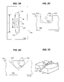
- FIG. 1 shows one embodiment of a fiber device that integrates or engages a fiber to a substrate with a groove for positioning the fiber and openings for holding the fiber.
- FIGS. 2A and 2B show a cross sectional view of the device in FIG. 1 along the direction AA′ and a side view of the device in FIG. 1 along the direction BB′, respectively.
- FIGS. 2C and 2D show examples of two different cross sections for grooves shown in FIG. 1 .
- FIG. 2E shows one example of a V groove with varying depth and width.
- FIG. 3A shows a design to engage a fiber on to a substrate by using an elongated groove with a single through hole, where a portion of the fiber cladding is removed and polished to form a side-polished evanescent coupling port.
- FIG. 3B shows another way of engaging a fiber onto a substrate without using through holes shown in FIG. 1 , where a portion of the fiber cladding is removed and polished to form a side-polished evanescent coupling port.
- FIG. 4 shows one exemplary fiber sensing device formed over a side-polished fiber.
- FIG. 5 shows measured optical losses as a function of the refractive index outside the metal layer in the sensor shown in FIG. 4 for different thickness values of the metal layer.
- FIG. 6 shows exemplary measurements of optical loss with the sensor in FIG. 4 in measuring a fluid with a probe wavelength at 1530.32 nm.
- FIG. 7 shows exemplary measurements of the ratio of optical losses with the sensor in FIG. 4 in measuring a mixture flow with different material components with two probe wavelengths at 1530.32 nm and 1553.32 nm, respectively.
- FIG. 8 shows a fiber sensing device that has two fiber sensors for respectively measuring presence of water and oil.
- FIG. 9 illustrates an example of the measured optical loss as a function of time by a sensor designed to have a high optical loss for a particular material when measuring a mixture flow with different material components.
- FIG. 10 shows exemplary measurements of optical losses with the sensor in FIG. 4 in measuring a mixture flow with different material components with a probe wavelength at 1550 nm.
- the optical sensing devices described in this application operate based on the dependence of the evanescent coupling at a side-polished surface of an optical waveguide on the refractive index of a material present at the external side of the side surface. This is because the evanescent coupling is sensitive to the boundary conditions at or near the side-polished surface. In general, if the environment around the side-polished surface changes, the evanescent coupling can change accordingly. This change can be reflected in the remaining guided light. Hence, a measurement of this change in the remaining guided light in the fiber or waveguide may be calibrated and used to measure the change in the environment.
- such an optical sensing device may include an optical waveguide having a side surface on the waveguide cladding within an evanescent field of guided light in the waveguide, and a metal layer formed on the side surface and having a thickness to transmit the evanescent field.
- An optical detector may be used to receive guided light in the waveguide passing through the side surface and to produce a detector output.
- a processing circuit may be provided to measure an optical loss of the guided light at the side surface from the detector output. The processing circuit is operable to extract a property of the medium above the metal layer from the measured optical loss.
- the waveguide may be implemented as planar waveguides, ridge waveguides, and embedded waveguides, and optical fiber. The implementations described here will use optical fiber as an example.
- optical fibers for implementing the sensing devices allows for convenience and flexibility in deployment of a sensor.
- fiber is commercially available at a much cheaper price than other waveguides.
- the fiber in the sensing devices of this application may be integrated on a substrate.
- One or more fibers may be integrated on or engaged to the substrate fabricated with one or more grooves.
- One portion of the cladding of each fiber is removed and polished to form a fiber coupling port as the sensing area.
- the polished surface on the fiber cladding is sufficiently close to the fiber core so that optical energy can be coupled via evanescent fields out of the fiber core for optical monitoring.
- Two or more such fiber coupling ports may be formed at different positions in each fiber when needed.
- the following sections first describe the basic structures for integrating fibers onto substrates for forming side-polished fiber coupling ports based on evanescent coupling. Implementations of fiber sensing devices based on such structures are then described in detail.
- FIG. 1 shows one embodiment of a fiber device 100 where a fiber 140 is integrated or engaged to a substrate 110 .
- the fiber device 100 may be used as a building block to construct a variety of fiber devices, including but not limited to, fiber optical monitors, fiber couplers, fiber attenuators, fiber modulators, fiber beam splitters, optical fiber switches, and fiber frequency-division multiplexers.
- FIGS. 2A and 2B show additional details of the fiber device 100 .
- the substrate 110 may be formed of various materials, such as semiconductors, insulators including dielectric materials (e.g., a glass, a quartz, a crystal, etc), metallic materials, or any other solid-state materials that can be processed to form the device features such as grooves and through holes disclosed herein.
- Two parallel and opposing substrate surfaces, 112 and 114 are generally flat and may be polished.
- An elongated groove 120 is formed in the substrate 110 on the surface 112 and is essentially a recess from the surface 112 .
- the groove 120 may be fabricated by removing a portion of the material from the substrate 110 through etching or other processes.
- the geometry of the groove 120 is generally elongated along a straight line as illustrated or along a curved line. Unless otherwise indicated, the following description will use straight-line grooves as examples. Some embodiments are described with specific reference to groove with V-shaped cross sections as shown by the groove 220 in FIG. 2D .
- the cross sections are generally not so limited and may also be other shapes as well, including rectangular as shown in FIG. 2A , U-shaped as shown by the groove 210 in FIG. 2C , a circularly shape or other suitable shapes. Unless specifically indicated otherwise, the techniques, structures, and applications disclosed in this application are generally applicable to grooves of different shapes.
- the width, W, of the groove 120 is generally greater than the diameter, d, of the fiber 140 and may either remain a constant or vary spatially along the groove 120 , e.g., increasing from the center towards the two ends as illustrated in the V groove 220 in FIG. 2E .
- the length, L, of the groove 120 may vary from one grove to another and can be determined based on specific requirements of applications.
- the depth D of the groove 120 may be a constant or may vary along the groove 120 , e.g., increasing from the center towards the two ends as shown in FIG. 2E . In general, at least a portion of the groove 120 has a depth D to expose a portion of the fiber cladding of the fiber 140 above the surface 112 while still keeping the fiber core below the surface 112 .
- This portion of the groove 120 exposes partial fiber cladding of the fiber 140 above the surface 112 while still keeping the fiber core below the surface 112 .
- Other portions of the groove 120 may have a depth that is at least the fiber diameter d so that the fiber can be essentially placed in the groove 120 below the surface 112 .
- the depth D of the entire groove 120 may be greater than fiber diameter d to avoid evanescent coupling of a guided mode.
- the following description will assume that at least a portion of a groove 120 to expose a portion of the fiber cladding above the surface 112 and adjacent portions sufficiently deep to keep the fiber below the surface 112 .
- the central portion of the groove 120 may have a depth D less than d but greater than (d+dc)/2 while the portions on either sides of the central portion may have a depth equal to or greater than the fiber diameter d.
- the fiber device 100 may include two openings 131 and 132 that are respectively formed at the two ends of the groove 120 and penetrate through the substrate 110 .
- the openings 131 and 132 are through holes extending between the two surfaces 112 and provide access from one surface ( 112 or 114 ) to another.
- the spacing between the openings 131 and 132 essentially determines the length L of the groove 120 .
- the aperture of the openings 131 and 132 should be sufficiently large to receive the fiber 140 , e.g., with a diameter greater than the diameter of the fiber 140 .
- the shape of the holes 131 and 132 may generally be in any suitable geometry.
- a portion of the fiber 140 is placed in the groove 120 near the surface 112 .
- the remaining portions 141 , 142 of the fiber 140 on both sides of the portion in the groove 120 are respectively fed through the first and second openings 131 , 132 to the other side 114 of the substrate 110 .
- the fiber 140 may be slightly pulled by moving the fiber portions 141 and 142 in opposite directions so that the portion of the fiber 140 in the groove 120 is in substantially full contact with the groove 120 .
- the cladding of the fiber 140 in this portion protrudes out of the surface 112 .
- the fiber core in this portion of the fiber is generally kept under the surface 112 .
- the cladding of a central portion of the fiber 140 between the holes 131 and 132 may be exposed. This protruded or exposed cladding is then removed and polished to form a flat surface 144 of a length L c that is above the fiber core 143 and is substantially coplanar with the surface 112 of the substrate 110 as illustrated in FIG. 2B .
- the flat surface 144 When the spacing, h, between the flat surface 144 and the fiber core 143 is sufficiently small (e.g., on the order of or less than one wavelength of optical energy), the flat surface 144 can be used to couple optical energy into or out of the fiber core 144 through the evanescent fields outside the fiber core.
- the length, L c of the flat surface 144 approximately represents the optical coupling length for the fiber device 100 .
- This coupling surface 144 may also be non-flat, e.g., curved to a certain extent, as long as it can transmit evanescent signals.
- the groove 120 may extend to one end side 310 of the substrate 110 so that one end 141 of the fiber 140 leaves the groove 120 without going through a through hole.
- FIG. 3B shows a conventional design 302 in which the groove 120 may extend to two opposing end sides 310 and 330 of the substrate 110 so that the fiber 140 is engaged to the groove 120 without relying on any through holes.
- the through holes in the substrate 110 shown in FIGS. 1 and 3A may be used to engage a single fiber on both sides of a substrate to form two or more side-polished coupling ports for evanescent coupling.
- two grooves may be formed on opposite sides of the substrate 110 to share a common through hole at ends.
- a fiber may be threaded through the substrate 110 to have one fiber portion in the groove on one side and another fiber portion in the groove on the opposite side of the substrate 110 .
- fiber coupling ports may be formed in the same fiber on both sides of the substrate 110 .
- This structure may be use to construct a variety of fiber devices, including stacking two substrates to provide optical coupling from a fiber in one substrate to another fiber in another substrate.
- the fabrication of this double-sided fiber structure may be implemented by polishing the substrate and the fiber on both sides as described
- FIG. 4 shows a fiber sensing device 400 for measuring material 460 present at its sensing area.
- the material 460 may be a flow of a mixture of different materials such as gases and liquids (e.g., water and oil).
- a fiber 140 with a core 140 A and a cladding 140 B has one portion whose cladding is partially removed to form a surface 144 .
- the surface 144 is within the extent of the evanescent field of the guided light in the fiber core 140 A.
- the surface 144 is polished to operate as the fiber coupling port.
- the amount of evanescent light at the surface 144 may be set at a desired percentage of the total guide ling in the fiber 140 by controlling the distance between the fiber core 140 A and the surface 144 during the fabrication phase.
- the evanescent light decays in magnitude exponentially with the distance. Hence, the closer the surface 144 to the fiber core 144 A, the higher the percentage of the evanescent light being coupled out of the fiber.
- the substrate 110 is shown to operate as a fiber support that holds the fiber 140 .
- the substrate 110 has two opposing surfaces 112 and 114 .
- a depth-varying groove 120 may be formed on the surface 112 of the substrate 110 .
- the cladding of the fiber portion where the surface 144 is formed protrudes above the surface 112 .
- the protruded cladding is then removed to form the surface 144 which is approximately coplanar with the surface 112 .
- Other portions of the fiber 140 in the groove 120 stay under the surface 112 .
- different ways may be used to engage the fiber 140 to the substrate 110 to form the fiber coupling port 144 for evanescent coupling.
- the fiber 140 generally may be any fiber, including single-mode fibers, multi-mode fibers, and birefringent fibers.
- the fiber 140 may be a polarization maintaining (PM) fiber to preserve the polarization state of light to be transmitted.
- PM polarization maintaining
- a metal layer 410 is formed over the surface 144 .
- Metals such as chromium (Cr), nickel (Ni), sliver (Ag) and others may be used.
- the metal layer 410 is designed to be sufficiently thin so that light in the evanescent field can transmit through the metal layer 410 to reach the material present above the metal layer 410 .
- the thickness of the metal layer 410 may be about or less than the depth of the electric field associated with the evanescent field in the metal layer 140 .
- the thickness of the metal layer 410 may be a few tens of nanometers. If the metal layer 410 is made of chromium, the thickness may be about tens of nanometers for a probe wavelength around 1550 nm.
- the evanescent field of the guided light is exposed to the external material 460 through the metal layer 410 .
- the external surface of the metal layer 410 is therefore the sensing area for the sensing device 400 .
- the metal layer 410 provides an interface to allow the device 400 to detect a material whose index varies from 1 to 1.6 or greater. To a certain extent, the evanescent field at the metal layer 410 excites plasma oscillations on the metal layer 410 and the energy in plasma oscillations is lost from the evanescent field.
- An optional protective layer 420 may be formed over the metal layer 410 to protect the metal layer 410 from being eroded or otherwise damaged by the material 460 .
- Different materials may be used for the protective layer 420 depending on the materials to be measured with the device 400 .
- Certain carbon-based coatings may be used as the protective layer 420 , such as diamond-like carbon films.
- the fiber sensing device 400 further includes a probe light source 430 to produce a probe light beam 401 at a selected probe wavelength.
- the source 430 may include, for example, a laser diode, a light-emitting diode (LED), or an Amplified Spontaneous Emission (ASE) source such as a polarized ASE source.
- the input probe light beam 401 transmits through the fiber 140 including the sensing area at the side surface 144 as an output probe beam 402 .
- An optical detector 440 is used to receive a portion or the entirety of the transmitted light 402 in the fiber 140 .
- the received transmitted light 402 is converted into a detector signal 403 .
- a signal processing circuit 450 is used to process the detector signal 403 to extract the desired information about the composition of the material mixture 460 .
- the circuit 450 may include calibrated optical losses for various materials that are obtained through a calibration process. The measured optical loss is then compared to the calibrated optical losses to pick out the matching materials in the material mixture 460 .
- the material mixture 460 may be a liquid flow with different contents, such as a mixture of different liquids and one or more gases.
- a mixture flow is a “multiphase” flow because it includes material compositions of different phases such as gases and liquids.
- it is common to have multiphase flow of mixed gas, water and oil from the flows obtained from the oil wells.
- it may be desirable to detect the presence of various constituents of such a mixture flow.
- optical properties of different components in the flow are generally different.
- various gaseous component of a multiphase flow has an optical index of refraction that is close to 1
- the refractive index of water is close to 1.333
- the refractive indices of various oils are generally greater than that of water, e.g., near 1.5.
- Such differences in optical indices of refraction may be used to measure the concentrations of different components in the flow.
- the sensing device 400 in FIG. 4 may be operable to measure the content fraction in a multiphase flow.
- the sensing area of the device 400 is small and thus may be occupied by one material component in the flow at a time.
- the guided light can be evanescently coupled out of the fiber 140 through the metal layer 410 and thus the remaining light in the fiber 140 is attenuated.
- the evanescent coupling strength through the side-polished surface varies with the effective optical index of refraction above the thin metallic layer 410 .
- the coupling strength changes. This dependence of the coupling strength may be measured and pre-calibrated for different flow components to measure the different phases in the flow.
- the light loss in the fiber 140 is sensitive to optical index of the material 460 above the metal layer 410 .
- the light source 430 may be coupled to the input end of the fiber 140 to inject probing light 401 at a selected probe wavelength and the optical detector 440 may be coupled to the output end of the fiber 140 to receive the attenuated output light 402 from the fiber 140 .
- the processing circuit 450 is coupled to receive the detector signal 403 from the optical detector 440 and produces an indication based on the pre calibration data as to whether a particular component is present in the flow under the measurement. In actual operation, the sensor is placed in contact with the flow, e.g., by being located in the flow or on the surface of the flow.
- FIG. 5 shows measurements of light loss Re as a function of the index of the material 460 over the metal layer 410 for different thickness values of Cr metal coatings as the metal layer 410 with the probe wavelength at 1550 nm in a fiber sensor based on the design in FIG. 4 .
- the values of the refractive index of the material 460 above the metal layer 410 are values at the wavelength of 589 nm.
- Measurements in FIG. 5 demonstrate that the light loss can change with the refractive index of the material 460 to create a maximum loss at a particular index for the material above the sensing port for a fixed probe wavelength. Based on this property of the design in FIG.
- different sensors with different thickness values for the metal layer 410 formed of the same metal may be designed to have different maximum losses for different material components in the multiphase flow.
- one such a sensor may be designed to exhibit a maximum loss when the water with a refractive index at about 1.333 is present above the sensing port.
- Another sensor may be designed to exhibit a maximum loss when an oil with a refractive index at about 1.5 is present above the sensing port.
- the thin metal layer 410 may be removed for sensing a material with a refractive index greater than the effective index (about 1.45) of the fiber 140 .
- the guided light in the fiber experiences no or very little loss for a material with an index below 1.45 to be present above the sensing port.
- a sensor without the metal layer 410 may be used to detect oil with a refractive index at about 1.5 in the multiphase flow.
- FIG. 6 shows measured output power of a sensor based on FIG. 4 as a function of the refractive index of a fluid under measurement.
- the sensor discriminates the phase of a material mixture by classifying the material as “oil” and “not oil.” This sensor has a high ratio of signal to noise in detecting the presence of oil.
- FIG. 6 also shows a large dynamic range of change in the refractive index of oil materials.
- the variation of optical power in the output 402 of the sensor 400 in FIG. 4 may be caused by various sources, including a variation in the probe light source 430 and a change in the evanescent coupling at the metal layer 410 caused by the change in the material 460 .
- the measurements of optical power of the output 402 may be carried out simultaneously at two separate wavelengths ⁇ 1 and ⁇ 2 within the output 402 .
- the ratio of the measured optical power levels at the two different wavelengths is then used to measure the optical loss caused by the change in the material 460 .
- two narrow passband filters at separate wavelengths ⁇ 1 and ⁇ 2 to filter and separate signals in the output 402 .
- the light source 410 may have a relatively wide spectral range in its emission to cover two sepparate wavelengths ⁇ 1 and ⁇ 2.
- the light source may be a polarized ASE source.
- two laser diodes operated at ⁇ 1 and ⁇ 2, respectively, may also be used and a modified ratio of light loss at ⁇ 1 and ⁇ 2 may be used.
- FIG. 7 shows the ratio of output power levels of optical signals at wavelengths 1530.32 nm and 1553.04 nm by using a sensor based on the design in FIG. 4 .
- the measured ratio is used to discriminate between the phase of gas and the non-gas phase with a ratio of signal to noise larger than 4 dB.
- the detector system uses two filters to select wavelengths of 1530.04 nm and 1553.04 nm, respectively.
- FIG. 8 shows an exemplary multiphase sensing device with two or more fiber sensors in a sensor package 810 in contact with a multiphase flow 800 .
- Each of the sensors is designed to measure one designated component of the multiphase flow 800 so that the sensors can simultaneously measure different components.
- Different optical detectors are coupled to different fibers to measure optical losses caused by presence of different flow components.
- a processing circuit 820 processes the detector signals from the different sensors to generate indicator signals which are displayed on a display unit of the processing circuit 820 . As illustrated, the display shows the gas and the water in a mixed oil flow.
- the percentage of each material in the mixture may also be determined by measuring the durations of the optical losses associated with different materials. This measurement is based on the assumption that the duration in which a particular material is present is proportional to the amount of that material in the mixture.
- FIG. 9 shows an exemplary signal out of a fiber sensor in the instrument in FIG. 8 .
- the measured optical loss in the output of the fiber sensor has separate periods of a high loss. When one sensor detects a high loss to the guided light, this indicates that the current portion of the flow on the surface of the sensor is the component it is designed to measure. Separate periods of the high loss represent the material which the sensor is specifically designed to measure is present at the sensor at different times. A period of a low loss in the signal indicates one or more other materials are present in the mixture flow that the present fiber sensor is not designed to have a high optical loss.
- the percentage of time during which such a high loss is measured has a direct correlation with the fraction of the component in the mixed multiphase flow. Hence, this measured percentage of time may be used to measure the content fraction of the particular component in the mixed flow.
- FIG. 10 shows some measured output power of a fiber sensor as a function of time. A high loss in the output of the sensor represents that oil material appears.
- Two or more differently configured sensors may be included in the instrument to respectively measure different materials.
- a two-sensor sensing instrument may have one sensor designed to measure air or water and the other to measure oil. The contents of the mixture flow with gas, water and oil may be determined by the processing circuit for the two sensors.
- a sensing device can be designed based on optical evanescent coupling through a side-polished fiber port or waveguide to measure the presence and content fraction of a selected flow component in a multiphase flow.
- a combination of two or more such side-polished fiber sensors may be used for measuring different flow components in a multiphase flow based on measurement of the optical attenuation in each fiber sensor. This allows for simultaneous and dynamic measurement of different components in a mixture flow.
Abstract
Description
Claims (20)
Priority Applications (1)
| Application Number | Priority Date | Filing Date | Title |
|---|---|---|---|
| US10/697,673 US7087887B1 (en) | 2002-10-31 | 2003-10-29 | Optical multiphase flow sensor |
Applications Claiming Priority (2)
| Application Number | Priority Date | Filing Date | Title |
|---|---|---|---|
| US42275502P | 2002-10-31 | 2002-10-31 | |
| US10/697,673 US7087887B1 (en) | 2002-10-31 | 2003-10-29 | Optical multiphase flow sensor |
Publications (1)
| Publication Number | Publication Date |
|---|---|
| US7087887B1 true US7087887B1 (en) | 2006-08-08 |
Family
ID=36758571
Family Applications (1)
| Application Number | Title | Priority Date | Filing Date |
|---|---|---|---|
| US10/697,673 Expired - Lifetime US7087887B1 (en) | 2002-10-31 | 2003-10-29 | Optical multiphase flow sensor |
Country Status (1)
| Country | Link |
|---|---|
| US (1) | US7087887B1 (en) |
Cited By (3)
| Publication number | Priority date | Publication date | Assignee | Title |
|---|---|---|---|---|
| US20120140232A1 (en) * | 2010-12-07 | 2012-06-07 | Forward Electronics Co., Ltd | SPR optical fiber sensor and SPR sensing device using the same |
| US10823666B2 (en) * | 2016-12-19 | 2020-11-03 | Indiana University Research And Technology Corporation | In-vitro optical transmittance test of LED on oral tissue |
| US11579083B2 (en) * | 2017-04-03 | 2023-02-14 | Indigo Diabetes N.V. | Implantable optical sensor |
Citations (17)
| Publication number | Priority date | Publication date | Assignee | Title |
|---|---|---|---|---|
| US4386269A (en) * | 1979-11-15 | 1983-05-31 | Avon Rubber Company Limited | Method and device for detecting leaks from pipelines |
| US4637729A (en) * | 1983-12-14 | 1987-01-20 | Carrier Corporation | Fiber optic moisture analysis probe |
| US5164608A (en) * | 1991-06-27 | 1992-11-17 | Hughes Aircraft Company | Plural wavelength fiber optic liquid level sensor for multiple liquids |
| US5168156A (en) * | 1991-06-28 | 1992-12-01 | The Standard Oil Company | Reflective evanescent fiber-optic chemical sensor |
| US5324933A (en) * | 1993-06-21 | 1994-06-28 | General Electric Company | High accuracy and high sensitivity environmental fiber optic sensor with corrugations |
| US5903685A (en) * | 1995-11-29 | 1999-05-11 | British Telecommunications Public Limited Company | Sensor arrangement |
| US6490391B1 (en) | 2000-07-12 | 2002-12-03 | Oluma, Inc. | Devices based on fibers engaged to substrates with grooves |
| US6501875B2 (en) | 2000-06-27 | 2002-12-31 | Oluma, Inc. | Mach-Zehnder inteferometers and applications based on evanescent coupling through side-polished fiber coupling ports |
| US6516114B2 (en) | 2000-06-27 | 2003-02-04 | Oluma, Inc. | Integration of fibers on substrates fabricated with grooves |
| US6542663B1 (en) | 2000-09-07 | 2003-04-01 | Oluma, Inc. | Coupling control in side-polished fiber devices |
| US6549713B1 (en) | 2000-06-27 | 2003-04-15 | Oluma, Inc. | Stabilized and integrated fiber devices |
| US6571035B1 (en) | 2000-08-10 | 2003-05-27 | Oluma, Inc. | Fiber optical switches based on optical evanescent coupling between two fibers |
| US6597833B1 (en) | 2000-06-27 | 2003-07-22 | Oluma, Inc. | Wavelength-division multiplexers and demultiplexers based on mach-zehnder interferometers and evanescent coupling |
| US6621951B1 (en) | 2000-06-27 | 2003-09-16 | Oluma, Inc. | Thin film structures in devices with a fiber on a substrate |
| US6621952B1 (en) | 2000-08-10 | 2003-09-16 | Oluma, Inc. | In-fiber variable optical attenuators and modulators using index-changing liquid media |
| US6625349B2 (en) | 2000-06-27 | 2003-09-23 | Oluma, Inc. | Evanescent optical coupling between a waveguide formed on a substrate and a side-polished fiber |
| US6650799B2 (en) * | 2001-09-18 | 2003-11-18 | Hampton University | Apparatus for and methods of sensing evanescent events in a fluid field |
-
2003
- 2003-10-29 US US10/697,673 patent/US7087887B1/en not_active Expired - Lifetime
Patent Citations (18)
| Publication number | Priority date | Publication date | Assignee | Title |
|---|---|---|---|---|
| US4386269A (en) * | 1979-11-15 | 1983-05-31 | Avon Rubber Company Limited | Method and device for detecting leaks from pipelines |
| US4637729A (en) * | 1983-12-14 | 1987-01-20 | Carrier Corporation | Fiber optic moisture analysis probe |
| US5164608A (en) * | 1991-06-27 | 1992-11-17 | Hughes Aircraft Company | Plural wavelength fiber optic liquid level sensor for multiple liquids |
| US5168156A (en) * | 1991-06-28 | 1992-12-01 | The Standard Oil Company | Reflective evanescent fiber-optic chemical sensor |
| US5324933A (en) * | 1993-06-21 | 1994-06-28 | General Electric Company | High accuracy and high sensitivity environmental fiber optic sensor with corrugations |
| US5903685A (en) * | 1995-11-29 | 1999-05-11 | British Telecommunications Public Limited Company | Sensor arrangement |
| US6516114B2 (en) | 2000-06-27 | 2003-02-04 | Oluma, Inc. | Integration of fibers on substrates fabricated with grooves |
| US6501875B2 (en) | 2000-06-27 | 2002-12-31 | Oluma, Inc. | Mach-Zehnder inteferometers and applications based on evanescent coupling through side-polished fiber coupling ports |
| US6549713B1 (en) | 2000-06-27 | 2003-04-15 | Oluma, Inc. | Stabilized and integrated fiber devices |
| US6556746B1 (en) | 2000-06-27 | 2003-04-29 | Oluma, Inc. | Integrated fiber devices based on Mach-Zehnder interferometers and evanescent optical coupling |
| US6597833B1 (en) | 2000-06-27 | 2003-07-22 | Oluma, Inc. | Wavelength-division multiplexers and demultiplexers based on mach-zehnder interferometers and evanescent coupling |
| US6621951B1 (en) | 2000-06-27 | 2003-09-16 | Oluma, Inc. | Thin film structures in devices with a fiber on a substrate |
| US6625349B2 (en) | 2000-06-27 | 2003-09-23 | Oluma, Inc. | Evanescent optical coupling between a waveguide formed on a substrate and a side-polished fiber |
| US6490391B1 (en) | 2000-07-12 | 2002-12-03 | Oluma, Inc. | Devices based on fibers engaged to substrates with grooves |
| US6571035B1 (en) | 2000-08-10 | 2003-05-27 | Oluma, Inc. | Fiber optical switches based on optical evanescent coupling between two fibers |
| US6621952B1 (en) | 2000-08-10 | 2003-09-16 | Oluma, Inc. | In-fiber variable optical attenuators and modulators using index-changing liquid media |
| US6542663B1 (en) | 2000-09-07 | 2003-04-01 | Oluma, Inc. | Coupling control in side-polished fiber devices |
| US6650799B2 (en) * | 2001-09-18 | 2003-11-18 | Hampton University | Apparatus for and methods of sensing evanescent events in a fluid field |
Non-Patent Citations (1)
| Title |
|---|
| Ramos, et al.; Oblique-Tip Fiber-Optic Sensors for Multiphase Fluid Discrimination; Journal of Lightwave Technology, vol. 17, No. 8, Aug. 1999. |
Cited By (3)
| Publication number | Priority date | Publication date | Assignee | Title |
|---|---|---|---|---|
| US20120140232A1 (en) * | 2010-12-07 | 2012-06-07 | Forward Electronics Co., Ltd | SPR optical fiber sensor and SPR sensing device using the same |
| US10823666B2 (en) * | 2016-12-19 | 2020-11-03 | Indiana University Research And Technology Corporation | In-vitro optical transmittance test of LED on oral tissue |
| US11579083B2 (en) * | 2017-04-03 | 2023-02-14 | Indigo Diabetes N.V. | Implantable optical sensor |
Similar Documents
| Publication | Publication Date | Title |
|---|---|---|
| US11346770B2 (en) | Optical fiber sensor for salinity and temperature measurement | |
| US20070098323A1 (en) | Reflection-mode fiber sensing devices | |
| US10866081B2 (en) | Waveguide interferometer | |
| Slavı́k et al. | Miniaturization of fiber optic surface plasmon resonance sensor | |
| US7697796B2 (en) | Plasmon-polariton refractive-index fiber bio-sensor with fiber Bragg grating | |
| US7085452B1 (en) | Optical devices having WGM cavity coupled to side-polished port | |
| Alonso et al. | New ‘in-line’optical-fibre sensor based on surface plasmon excitation | |
| del Carmen Alonso-Murias et al. | SPR fiber tip sensor for the simultaneous measurement of refractive index, temperature, and level of a liquid | |
| US20090216419A1 (en) | Methods and Apparatus for Optical Monitoring of Fluid | |
| Rodríguez-Quiroz et al. | Hybrid fiber Fabry–Perot interferometer with improved refractometric response | |
| EP0196168B1 (en) | Fiber optic doppler anemometer | |
| US7773640B2 (en) | Fiber laser device | |
| ZA200508065B (en) | A fibre optic sensor for measurement of refractive index | |
| Qiu et al. | Plasmonic fiber-optic refractometers based on a high Q-factor amplitude interrogation | |
| Sohn | Liquid sensors using refractive intensity at the end-face of a glass fiber connected to fiber-Bragg grating | |
| JP2022153599A (en) | Optical sensor and analyzing device using the same | |
| TWI424155B (en) | Surface plasmon resonance sensor | |
| US7952772B2 (en) | Photonic crystal fiber sensor | |
| US7068868B1 (en) | Sensing devices based on evanescent optical coupling | |
| US7087887B1 (en) | Optical multiphase flow sensor | |
| JP4770449B2 (en) | Optical waveguide device, temperature measuring device, and temperature measuring method | |
| Chu et al. | Surface plasmon resonance sensors using silica‐on‐silicon optical waveguides | |
| JP6406750B2 (en) | Optical fiber measurement method and optical fiber measurement device | |
| Apriyanto et al. | A multimode fiber refractive index sensor | |
| US20040105607A1 (en) | Method and apparatus for continuous measurement of the refractive index of fluid |
Legal Events
| Date | Code | Title | Description |
|---|---|---|---|
| AS | Assignment |
Owner name: OLUMA, INC., CALIFORNIA Free format text: ASSIGNMENT OF ASSIGNORS INTEREST;ASSIGNORS:PI, BO;ZHAO, SHULAI;CHEN, ZHIHAO;REEL/FRAME:014659/0864 Effective date: 20031029 |
|
| STCF | Information on status: patent grant |
Free format text: PATENTED CASE |
|
| AS | Assignment |
Owner name: IFOS, INC., CALIFORNIA Free format text: ASSIGNMENT OF ASSIGNORS INTEREST;ASSIGNOR:FOUNDATION CAPITAL III, LP;REEL/FRAME:019265/0777 Effective date: 20050727 |
|
| AS | Assignment |
Owner name: INTELLIGENT FIBER OPTIC SYSTEMS CORPORATION, CALIF Free format text: ASSIGNMENT OF ASSIGNORS INTEREST;ASSIGNOR:IFOS, INC.;REEL/FRAME:019265/0799 Effective date: 20070101 |
|
| FPAY | Fee payment |
Year of fee payment: 4 |
|
| REMI | Maintenance fee reminder mailed | ||
| FPAY | Fee payment |
Year of fee payment: 8 |
|
| SULP | Surcharge for late payment |
Year of fee payment: 7 |
|
| FEPP | Fee payment procedure |
Free format text: MAINTENANCE FEE REMINDER MAILED (ORIGINAL EVENT CODE: REM.) |
|
| FEPP | Fee payment procedure |
Free format text: 11.5 YR SURCHARGE- LATE PMT W/IN 6 MO, SMALL ENTITY (ORIGINAL EVENT CODE: M2556) |
|
| MAFP | Maintenance fee payment |
Free format text: PAYMENT OF MAINTENANCE FEE, 12TH YR, SMALL ENTITY (ORIGINAL EVENT CODE: M2553) Year of fee payment: 12 |