US708564A - Wagon-brake. - Google Patents
Wagon-brake. Download PDFInfo
- Publication number
- US708564A US708564A US10484902A US1902104849A US708564A US 708564 A US708564 A US 708564A US 10484902 A US10484902 A US 10484902A US 1902104849 A US1902104849 A US 1902104849A US 708564 A US708564 A US 708564A
- Authority
- US
- United States
- Prior art keywords
- brake
- wagon
- tongue
- lever
- hounds
- Prior art date
- Legal status (The legal status is an assumption and is not a legal conclusion. Google has not performed a legal analysis and makes no representation as to the accuracy of the status listed.)
- Expired - Lifetime
Links
- 238000010276 construction Methods 0.000 description 4
- 241001465754 Metazoa Species 0.000 description 2
- 238000004904 shortening Methods 0.000 description 2
- 230000008878 coupling Effects 0.000 description 1
- 238000010168 coupling process Methods 0.000 description 1
- 238000005859 coupling reaction Methods 0.000 description 1
- 230000000630 rising effect Effects 0.000 description 1
Images


Classifications
-
- B—PERFORMING OPERATIONS; TRANSPORTING
- B62—LAND VEHICLES FOR TRAVELLING OTHERWISE THAN ON RAILS
- B62B—HAND-PROPELLED VEHICLES, e.g. HAND CARTS OR PERAMBULATORS; SLEDGES
- B62B5/00—Accessories or details specially adapted for hand carts
- B62B5/04—Braking mechanisms; Locking devices against movement
- B62B5/0404—Braking mechanisms; Locking devices against movement automatic
Definitions
- This invention relates to wagon or vehicle brakes, the object in view being to provide a simple and effective brake mechanism applicable to wagons or trucks which are longitudinally extensible and especially designed for carrying lumber of different lengths.
- the brake mechanism is so constructed with reference to the extensible running-gear of the wagon that the brake connections may also be extended to correspond with the length of the running-gear of the wagon, the necessary adjustment being quickly efiected.
- A'further object of the invention is to provide means whereby the tongue is left free to rise and fall and also to move longitudinally with relation to the running-gear in order to apply and release the brake-shoes.
- Another object of the invention is to so arrange the brake-levers and connections as to obtain the greatest purchase or leverage While keeping the parts in compact shape.
- the invention consists in the novel construction, combination, and arrangement of parts, as hereinafter fully described, illustrated, and claimed.
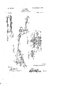
- Figure 1 is a plan view of a wagon, showing the improved brake mechanism applied thereto.
- Fig. 2 is a side elevation of the same with the wheels removed.
- Fig. 3 is a central vertical longitudinal section through the same.
- Fig. at is a detail perspective view of the brake mechanism, some of the parts being omitted for the purpose of better illustration.
- Fig. 5 is an enlarged vertical section taken longitudinally of the front axle or bolster.
- Fig. (iis a detail cross-section through the front hounds or braces and tongue.
- Fig. 7 is a detail vertical cross-section showing the means for hanging the brake-beam.
- the front hounds or braces 7 have their forward end portions 8 arranged parallel to each other and connected by cross-pieces or tie-plates 9 and also by means of a stay-bolt 10, which passes through a slot 11, extending longitudinally of the tongue, thus enabling the tongue to slide to a limited extent and lengthwise between the end portions 8 of the front hounds, the purpose of which will hereinafter appear.
- the rear ends of the front hounds are connected by a curved crossbar 12, while above the cross-bar 12 is arranged a curved guide-rail 13, the reach-pole 6 passing between the bar 12 and rail 13, as shown in Figs. 2 and 3.
- the reach-pole 6 is connected with the front axle 1 by means of the king-bolt 14, which passes through the axle, as shown in Fig. 5, and also through the front bolster 15.
- the brake mechanism comprises, essentially, a brake-beam 16, having brake-shoes 17, arranged to bear against the rear wheels and suspended by means of hanging links 18 from across-bar 19, supported, by preference, on the rear hounds, being fastened thereto in any convenient manner.
- a bifurcated link 20 Pivotally connected with the center of the brake-beam 16 is a bifurcated link 20, which extends rearward and pivotally connects with the lower arm 21 of a lever, the other arm 22 of which extends upward and connects pivotally at 23 with an extensible brake-rod 24:. Intermediate its upper and lower ends the lever 21. 22
- the brake-rod 24 is longitudinallyextensible, comprising a tubular section which connects with the upper arm 22 of the rear brake-lever and a telescopic section or rod 27, which is slidingly fitted in the tubular section and adapted to be held at any desired point of adjustment by means of a removable pin 28 passing through an opening in the tubular section and adapted to be inserted in any one of a longitudinal series of openings 29 in the inner section or rod 27.
- This construction provides for lengthening and shortening the brake connections to correspond with the length of the running-gear of the wagon in adapting the latter to lumber of different lengths.
- the inner section or rod 27 is connected at its forward end to a tumbling extension 30 by means of a universal joint 31, and said tumbling extension is connected by a similar universal joint 32 with the upper end and arm 33 of a forward brakelever, the lower arm 34 of which is curved in a downward and forward direction and also provided with a curved slot 35, which receives a pin or bolt 36 at the rear end of the tongue or draft-pole 37.
- the forward brake-lever 33 34 is provided with a rock-shaft 38, the ends of which are journaled in bearings 39, mounted, by preference, upon the upper sides of the forward hounds 7, as shown in Fig. 1.
- the slidable tongue 37 has its rear end curved downward, as best shown in Figs. 2, 3, and 4, so as to engage the lower portion of the arm 34 on the forward brakelever.
- the slot 35 allows the rear end of the tongue to move upward and downward, as in passing through a ditch or gulley or over a mound, and the front tie-plate or cross-piece 9 is also arched or offset in an upward direction to accommodate the up-and-down movements of the tongue in advance of the staybolt 11.
- the inner section or rod 27 of the extensible brake-rod 24 is longitudinally slotted, as shown at 40, to straddle the king-bolt 14 and admit of the necessary lengthwise movement of the brake-rod in applying the brakes.
- the whiffletree 41 may be pivotally connected with the tongue 37 at any convenient point.
- the tongue is left free to rise and fall in accommodating the movements of the animals and also to play lengthwise to an extent necessary to apply or release the brake-shoes.
- the brakes are applied automatically in coming downhill by the back pull of the animals, while in drawing the load on a level road or uphill the stay-bolt 11 takes the strain and does away with the usual bu mpers.
- By giving a downward curve or extension to the rear end of the tongue or draftpole greater leverage is obtained for applying the brakes, and by slotting the lower arm of the forward brake-lever the rising and falling movements of the tongue are not interfered with.
- the tumbling extension at the forward end of the brake-rod provides for all the necessary play in turning the wagon and avoids all binding or cramping of the parts.
- the brake connections may be lengthened or shortened according with the length of the wagon itself.
Landscapes
- Engineering & Computer Science (AREA)
- Chemical & Material Sciences (AREA)
- Combustion & Propulsion (AREA)
- Transportation (AREA)
- Mechanical Engineering (AREA)
- Braking Arrangements (AREA)
Description
P. LEWIS.
WAGON BRAKE. (Application filed Apr.
Patenied Sept. 9, I902.
3 Sheets-Sheet I.
(No Model.)
3 u oemfoz P/wga s q vitumma Len 0'5 Patented Sept: 9, I902.
P. LEWIS.
WAGON BRAKE.
(Application filed Apr. 26, 1902.)
a Sheets-She'd z.
' Snow 1km,
Wilmeowo llNiiiE drains Parnt PHELPS LEWIS, OF YOCUM, KENTUCKY.
WAGON-BRAKE.
SPECIFICATION forming part of Letters Patent No. 708,564, dated September 9, 1902.
Application filed April 26, 1902. Serial 110,104,849. (No model.)
To all whom it may concern:
Be it known thatl, PHELPS LEWIS, acitizen of the United States, residing at Yocum, in the county of Morgan and State of Kentucky, have invented certain new and useful Improvementsin Wagon-Brakes; and I do hereby declare the following to be a full, clear, and exact description of the invention, such as will enable others skilled in the art to which it appertains to make and use the same.
This invention relates to wagon or vehicle brakes, the object in view being to provide a simple and effective brake mechanism applicable to wagons or trucks which are longitudinally extensible and especially designed for carrying lumber of different lengths. The brake mechanism is so constructed with reference to the extensible running-gear of the wagon that the brake connections may also be extended to correspond with the length of the running-gear of the wagon, the necessary adjustment being quickly efiected.
A'further object of the invention is to provide means whereby the tongue is left free to rise and fall and also to move longitudinally with relation to the running-gear in order to apply and release the brake-shoes.
Another object of the invention is to so arrange the brake-levers and connections as to obtain the greatest purchase or leverage While keeping the parts in compact shape.
These and other objects of the invention will appear more fully as the description proceeds.
The invention consists in the novel construction, combination, and arrangement of parts, as hereinafter fully described, illustrated, and claimed.
In the accompanying drawings, Figure 1 is a plan view of a wagon, showing the improved brake mechanism applied thereto. Fig. 2 is a side elevation of the same with the wheels removed. Fig. 3 is a central vertical longitudinal section through the same. Fig. at is a detail perspective view of the brake mechanism, some of the parts being omitted for the purpose of better illustration. Fig. 5 is an enlarged vertical section taken longitudinally of the front axle or bolster. Fig. (iis a detail cross-section through the front hounds or braces and tongue.
Fig. 7 is a detail vertical cross-section showing the means for hanging the brake-beam.
Like reference-numerals designate corresponding parts in all the figures of the draware the forwardly-converging hounds 4, the
front ends of which are arranged in parallel relation and connected by tie-plates or crosspieces 5, while the reach-pole 6 is slidingly fitted between the hounds 4 and secured in any convenient manner, thereby providing for the lengthening and shortening of the running-gear in the usual manner.
The front hounds or braces 7 have their forward end portions 8 arranged parallel to each other and connected by cross-pieces or tie-plates 9 and also by means of a stay-bolt 10, which passes through a slot 11, extending longitudinally of the tongue, thus enabling the tongue to slide to a limited extent and lengthwise between the end portions 8 of the front hounds, the purpose of which will hereinafter appear. The rear ends of the front hounds are connected by a curved crossbar 12, while above the cross-bar 12 is arranged a curved guide-rail 13, the reach-pole 6 passing between the bar 12 and rail 13, as shown in Figs. 2 and 3. At its forward end the reach-pole 6 is connected with the front axle 1 by means of the king-bolt 14, which passes through the axle, as shown in Fig. 5, and also through the front bolster 15.
The brake mechanism comprises, essentially, a brake-beam 16, having brake-shoes 17, arranged to bear against the rear wheels and suspended by means of hanging links 18 from across-bar 19, supported, by preference, on the rear hounds, being fastened thereto in any convenient manner. Pivotally connected with the center of the brake-beam 16 is a bifurcated link 20, which extends rearward and pivotally connects with the lower arm 21 of a lever, the other arm 22 of which extends upward and connects pivotally at 23 with an extensible brake-rod 24:. Intermediate its upper and lower ends the lever 21. 22
is provided with a rock-shaft 25, the end portions of which are journaled in bearings 26, secured, by preference, to the lower sides of the rear hounds in order to give suliicient length to the upper arm 22 of the lever to apply the brake-shoes to the wheels with the necessary force. The brake-rod 24 is longitudinallyextensible, comprisinga tubular section which connects with the upper arm 22 of the rear brake-lever and a telescopic section or rod 27, which is slidingly fitted in the tubular section and adapted to be held at any desired point of adjustment by means of a removable pin 28 passing through an opening in the tubular section and adapted to be inserted in any one of a longitudinal series of openings 29 in the inner section or rod 27. This construction provides for lengthening and shortening the brake connections to correspond with the length of the running-gear of the wagon in adapting the latter to lumber of different lengths. The inner section or rod 27 is connected at its forward end to a tumbling extension 30 by means of a universal joint 31, and said tumbling extension is connected by a similar universal joint 32 with the upper end and arm 33 of a forward brakelever, the lower arm 34 of which is curved in a downward and forward direction and also provided with a curved slot 35, which receives a pin or bolt 36 at the rear end of the tongue or draft-pole 37. Intermediate its ends the forward brake-lever 33 34 is provided with a rock-shaft 38, the ends of which are journaled in bearings 39, mounted, by preference, upon the upper sides of the forward hounds 7, as shown in Fig. 1. In order to obtain the necessary leverage for applying the brakes with the required force, the slidable tongue 37 has its rear end curved downward, as best shown in Figs. 2, 3, and 4, so as to engage the lower portion of the arm 34 on the forward brakelever. The slot 35 allows the rear end of the tongue to move upward and downward, as in passing through a ditch or gulley or over a mound, and the front tie-plate or cross-piece 9 is also arched or offset in an upward direction to accommodate the up-and-down movements of the tongue in advance of the staybolt 11. The inner section or rod 27 of the extensible brake-rod 24 is longitudinally slotted, as shown at 40, to straddle the king-bolt 14 and admit of the necessary lengthwise movement of the brake-rod in applying the brakes. The whiffletree 41 may be pivotally connected with the tongue 37 at any convenient point.
From the foregoing description it will be understood that the tongue is left free to rise and fall in accommodating the movements of the animals and also to play lengthwise to an extent necessary to apply or release the brake-shoes. The brakes are applied automatically in coming downhill by the back pull of the animals, while in drawing the load on a level road or uphill the stay-bolt 11 takes the strain and does away with the usual bu mpers. By giving a downward curve or extension to the rear end of the tongue or draftpole greater leverage is obtained for applying the brakes, and by slotting the lower arm of the forward brake-lever the rising and falling movements of the tongue are not interfered with. The tumbling extension at the forward end of the brake-rod provides for all the necessary play in turning the wagon and avoids all binding or cramping of the parts. It will also be apparent that the brake connections may be lengthened or shortened according with the length of the wagon itself.
I do not desire to be limited to the exact details of construction hereinabove set forth, and accordingly reserve the right to change, modify, or vary the construction within the scope of the appended claim.
Having thus described the invention, what is claimed as new, and desired to be secured by Letters Patent, is- In a wagon-brake, the combination with a wheeled truck, of a brake-beam provided with brake-shoes, a brake-lever connected with said beam, a second brake-lever mounted on the truck and provided with a curved and slotted arm, a slidable tongue having a downwardly-deflected and slotted rear end portion carrying a pin which works in the curved and slotted arm of the second brake-lever,a brakerod extending between the two brake-levers and pivotally connected therewith, and a universal coupling associated with the brakerod between its points of connection with the brake-levers, substantially as and for the purpose described.
In testimony whereof I affix my signature in presence of two witnesses.
PHELPS LEWIS. [1,. s.]
Witnesses:
BEN M. CARR, JAMES H. SEBASTIAN.
Priority Applications (1)
| Application Number | Priority Date | Filing Date | Title |
|---|---|---|---|
| US10484902A US708564A (en) | 1902-04-26 | 1902-04-26 | Wagon-brake. |
Applications Claiming Priority (1)
| Application Number | Priority Date | Filing Date | Title |
|---|---|---|---|
| US10484902A US708564A (en) | 1902-04-26 | 1902-04-26 | Wagon-brake. |
Publications (1)
| Publication Number | Publication Date |
|---|---|
| US708564A true US708564A (en) | 1902-09-09 |
Family
ID=2777093
Family Applications (1)
| Application Number | Title | Priority Date | Filing Date |
|---|---|---|---|
| US10484902A Expired - Lifetime US708564A (en) | 1902-04-26 | 1902-04-26 | Wagon-brake. |
Country Status (1)
| Country | Link |
|---|---|
| US (1) | US708564A (en) |
Cited By (1)
| Publication number | Priority date | Publication date | Assignee | Title |
|---|---|---|---|---|
| US2453265A (en) * | 1948-01-29 | 1948-11-09 | William K Robinson | Educational device |
-
1902
- 1902-04-26 US US10484902A patent/US708564A/en not_active Expired - Lifetime
Cited By (1)
| Publication number | Priority date | Publication date | Assignee | Title |
|---|---|---|---|---|
| US2453265A (en) * | 1948-01-29 | 1948-11-09 | William K Robinson | Educational device |
Similar Documents
| Publication | Publication Date | Title |
|---|---|---|
| US708564A (en) | Wagon-brake. | |
| US299031A (en) | smoot | |
| US296171A (en) | jones | |
| US58014A (en) | Improvement in wagon-brakes | |
| US345599A (en) | Automatic brake for vehicles | |
| US210030A (en) | Improvement in automatic brakes for wagons | |
| US317846A (en) | Automatic vehicle-brake | |
| US297490A (en) | Vehicle-brake | |
| US745779A (en) | Vehicle-brake. | |
| US185262A (en) | Improvement in automatic brake-locks | |
| US710651A (en) | Wagon-brake. | |
| US423356A (en) | thayee | |
| US570345A (en) | Vehicle-brake | |
| US759666A (en) | Automatic brake. | |
| US387022A (en) | Automatic vehicle-brake | |
| US133644A (en) | Improvement in self-acting wagon-brakes | |
| US774084A (en) | Automatic brake for vehicles. | |
| US550872A (en) | Vehicle-brake | |
| US610827A (en) | Automatic vehicle-brake | |
| US488644A (en) | Automatic wagon-brake | |
| US357870A (en) | Automatic wagon-brake | |
| US739767A (en) | Wagon-brake. | |
| US547020A (en) | Wagon-brake | |
| US346196A (en) | Automatic wagon-brake | |
| US193044A (en) | Improvement in automatic wagon-brakes |