US7075298B2 - Method and apparatus for well logging using NMR with a long conductive rare-earth magnet and excitation compensation in the area of the long magnet - Google Patents
Method and apparatus for well logging using NMR with a long conductive rare-earth magnet and excitation compensation in the area of the long magnet Download PDFInfo
- Publication number
- US7075298B2 US7075298B2 US10/466,232 US46623203A US7075298B2 US 7075298 B2 US7075298 B2 US 7075298B2 US 46623203 A US46623203 A US 46623203A US 7075298 B2 US7075298 B2 US 7075298B2
- Authority
- US
- United States
- Prior art keywords
- radio frequency
- magnet
- long magnet
- coil
- field
- Prior art date
- Legal status (The legal status is an assumption and is not a legal conclusion. Google has not performed a legal analysis and makes no representation as to the accuracy of the status listed.)
- Expired - Lifetime
Links
Images


Classifications
-
- G—PHYSICS
- G01—MEASURING; TESTING
- G01V—GEOPHYSICS; GRAVITATIONAL MEASUREMENTS; DETECTING MASSES OR OBJECTS; TAGS
- G01V3/00—Electric or magnetic prospecting or detecting; Measuring magnetic field characteristics of the earth, e.g. declination, deviation
- G01V3/18—Electric or magnetic prospecting or detecting; Measuring magnetic field characteristics of the earth, e.g. declination, deviation specially adapted for well-logging
- G01V3/32—Electric or magnetic prospecting or detecting; Measuring magnetic field characteristics of the earth, e.g. declination, deviation specially adapted for well-logging operating with electron or nuclear magnetic resonance
Definitions
- the invention relates to geophysical methods for sensing wells, and in particular to nuclear magnetic logging (NML) used to study oil and gas wells.
- NML nuclear magnetic logging
- NML methods exist which use strong solenoid magnets to generate a static magnetic field in an area located near the wellbore wall, and which generate a radio frequency field in this area, predominantly perpendicular to the static magnetic field, and receive the nuclear magnetic resonance signals [1, 2].
- these methods have not gained wide application.
- An NML method exists which includes use of a system of focusing magnets to generate a uniform static magnetic field in the area located opposite the system of magnets in direct proximity to the wellbore wall, generate a radio frequency field in this area, with the direction of the radio frequency field being predominantly perpendicular to the static magnetic field, and receive this nuclear magnetic resonance signal from this area [3].
- the defect of this method is the shallow depth of the sensing zone, which is located at a distance of the order of 3 cm from the wall of the sonde. In wellbores with voids, the sensing region is in the wellbore area, which leads to spurious results.
- the device using this method consists of a circular cylindrical magnet made of ferrite and magnetized perpendicular to its long axis, and a radio frequency coil wound directly on the magnet, with the coil turns primarily lying on the plane passing through the axis of the magnet and the direction of its magnetization [4, sections 14, 15, 16], a radio pulse generator, a nuclear magnetic resonance signal receiver and a matching device; the start of the radio frequency coil is connected to the first input of said matching device, and the end of said coil is connected to the common point on the matching device; the output of the radio pulse generator is connected to the second input of said matching device, while the output of the matching device is connected to the input of the nuclear magnetic resonance signal receiver [4, 4].
- the sensing zone lies in a thin (of the order of 1 mm) cylindrical region coaxial with the axis of the sonde, at a significant distance from its axis.
- the sensing zone is located at a distance of 175 mm from its axis, and is hardly ever in the region of the wellbore with the standard diameter of 200 mm [5].
- the defect is that, as the sonde diameter decreases (to 114 mm, for example), the sensitivity of the sonde and the radius of the investigation zone decrease, and thus it can only operate in small-diameter wellbores [5].
- This defect is caused by the fact that the prototype device [4] used a circular cylindrical nonconducting ferrite magnet, while the radio frequency coil was wound directly on the surface of the magnet [4, sections 14, 15, 16].
- the problem stated is solved as follows.
- the nuclear magnetic logging method including generation of a static magnetic field in the wellbore, in the region to be analyzed, using one of several magnets made of a conducting rare-earth material with the longitudinal axis and a direction of magnetization running primarily perpendicular to such axis, generation of the exciting radio frequency field in the direction perpendicular to both the axis and the static magnetic field, and reception of the nuclear magnetic resonance signals from the excited nuclei, and also a compensating device such as a compensating coil generates a compensating radio frequency field in the area of the magnet.
- the nuclear magnetic logging apparatus having at least one long magnet, magnetized perpendicular to its longitudinal axis, and a radio frequency coil creating a field perpendicular to the field of the magnet, a radio pulse generator, a nuclear magnetic resonance signal receiver and a matching device, with the start of the radio frequency coil connected to the first input of the matching device and the end of the coil connected to the common point of the matching device, to the second input of which the output of the radio pulse generator is connected, while the output of the matching device is connected to the input of the nuclear magnetic resonance signal receiver, the magnet is made of a conducting rare-earth material in the form of an elongated parallelepiped. It is magnetized perpendicular to its longitudinal axis and wide lateral surface.
- the width of the magnet is twice the width of its narrow side, while the radio frequency coil is wound on a cylinder with a diameter at least equal to the diagonal of the cross section of the magnet located inside the cylinder.
- the turns of the coil lie on planes parallel to the longitudinal axis of the magnet and perpendicular to its narrow side in symmetric sectors located opposite the wide lateral surfaces of the magnet, while a compensating device is placed along the wide lateral surfaces of the magnet, parallel to its longitudinal axis.
- the compensating device has a coil with its beginning connected to a common point on the matching device, while its end is connected to one end of the radio frequency coil.
- the ratio of the coils of the radio frequency coil to the compensating coil is equal to the ratio of the diameter of the radio frequency coil to the thickness of the magnet.
- the compensating device has a shorted coil made of a material with resistivity less than 2.5 ⁇ 10 ⁇ 8 ohms ⁇ m.
- the improvement in this nuclear magnetic logging method in comparison with the prior technique is that compensation of the radio frequency field in the area of the magnet is proposed.
- a radio frequency field is also generated in the area of the magnet, directed toward and equal in strength to the exciting radio frequency field in the area of the magnet.
- the improvement in the design of the nuclear magnetic logging apparatus is that the magnet is made of a conducting rare-earth material in the shape of a long parallelepiped magnet that is magnetized perpendicular to its longitudinal axis and wide lateral surface, while the radio frequency coil is wound on a cylinder with diameter no less than the diagonal of the cross section of the magnet located inside the cylinder.
- the turns of the coil lie on planes parallel to the longitudinal axis of the magnet and parallel to its narrow side in symmetric sectors located opposite the wide lateral surface of the magnet.
- a compensating device is arranged along the wide lateral surfaces of the magnet, parallel to its longitudinal axis.
- the compensating device has a coil with its beginning connected to the common point on the matching device, while its end is connected to an end of the radio frequency coil.
- the ratio of the turns of the radio frequency coil to the compensating coil is equal to the ratio of the diameter of the radio frequency coil to the thickness of the magnet.
- the compensating device has a shorted coil made of a material with resistivity less than 2.5 ⁇ 10 ⁇ 8 ohms ⁇ m.
- any materials (except dielectrics) placed inside the radio frequency coil lead to losses in the radio frequency coil. This is manifested as a decrease in the Q-factor of the coil at the resonance frequency and ultimately a decrease in the signal-to-noise ratio at the output of the apparatus. Therefore, a ferrite magnet with “nonconductive” properties is used in the prior art device.
- the long circular cylindrical magnet in the prior art creates a static magnetic field with strength and direction at each point in the space surrounding it which can be determined using the following expression [6, 7]:
- H r , H ⁇ are the radial and tangential components of the field of the magnet at a point with coordinates r, ⁇ in a cylindrical coordinate system with an axis coinciding with the axis of the magnet
- H 0 is the field strength at the surface of
- the field of the magnet practically contains only the first harmonic from expression (1).
- This field is homogeneous (in magnitude) in the azimuthal direction at fixed radius r p .
- the quantity H 0 is directly proportional to the magnitude of the residual magnetism of the magnet material B r .
- a sensing zone r p 170–180 mm from the axis of the sonde in the prior art with field strength in this zone of the order of 165–170 gauss is generally selected for nuclear magnetic logging [5].
- a ferrite magnet with diameter of 120 mm is required to obtain this field strength in this sensing zone.
- a magnet made of NdFeB will have diameter of 65–70 mm. Therefore, the switch to a magnet made of NdFeB creates the prerequisites for fabricating a nuclear magnetic logging sonde with smaller diameter without reducing the radius of the sensing zone.
- a magnet made of ferrite as used in the prior art is “nonconducting”.
- the prior art radio frequency coil wound on its surface has a Q-factor of the order of 100 [5].
- a magnet made of NdFeB conducts the electrical current better, and the radio frequency coil wound on its surface will have a Q-factor of no more than 20.
- To reduce the losses in the radio frequency coil it is necessary to reduce the cross section surface of the material inserted inside the radio frequency coil and intersecting the electromagnetic flux of such coil, and to eliminate the radio frequency field in the area of the material inserted inside the coil.
- the proposed new method and apparatus for nuclear magnetic logging make it possible to solve these problems.
- the shape of the magnet be changed.
- the magnet is made thinner in the plane perpendicular to the direction of the flux of the radio frequency coil and wider in the direction of magnetization of the magnet.
- h the narrow lateral surface of the magnet
- D the wide lateral surface of the magnet
- H 0 the field strength of the magnet at its narrow lateral surface.
- the field strength in the sensing zone will be two times greater than that of a circular cylindrical magnet with diameter equal to the narrow lateral surface.
- a similar field strength can be obtained with a circular cylindrical magnet with diameter ⁇ square root over (2) ⁇ times greater than the width of the narrow lateral surface of a rectangular magnet made of the same material.
- the radio frequency coil for a sonde with a magnet in the shape of a parallelepiped is wound on a cylinder with a diameter no less than the cross section of the rectangular magnet.
- the coil turns are placed along the generatrix of the cylinder along its long axis in symmetric sectors with an angle 2 ⁇ arranged opposite the wide side of the rectangular magnet.
- the field strength and direction of the radio frequency coil can be determined from an expression analogous to (1):
- the field direction of the radio frequency coil at all points in the surrounding space is rotated 90° relative to the field of the magnet.
- H 1 0 is the radio frequency field strength at the wall of the radio frequency coil.
- H1 0 I ⁇ W ⁇ ⁇ ⁇ ⁇ R , ( 4 )
- I ⁇ ⁇ ⁇ is the current density through a radio frequency coil with radius R and a number of turns W.
- the radio frequency field in the azimuthal direction is practically uniform within the radius of the sensing zone r p . Furthermore, the energy arriving from the radio pulse generator is primarily expended to create the second, useful harmonic of the radio frequency field.
- the losses in the radio frequency coil will be identical when a planar magnet and a cylindrical magnet with diameter equal to the narrow side of the planar magnet are placed inside the radio frequency coil.
- the field strength of the planar magnet will be two times greater.
- the difference between the diameter of the radio frequency coil and the thickness of the planar magnet makes it possible to use a compensating coil which is wound directly on the magnet on the plane parallel to its narrow side.
- the compensating coil is connected opposite the primary, radio frequency coil.
- the ratio of the turns of the compensating coil to that of the radio frequency coil must be equal to the ratio of their radii.
- the absence of a radio frequency field in the area of the magnet leads to the absence of losses in the radio frequency coil caused by the presence of the magnet inside it.
- the strength of the useful radio frequency field in the sensing zone decreases insignificantly here, as is shown in FIG. 4 . For example, if the thickness of the magnet is 40 mm, while the diameter of the radio frequency coil is 100 mm, then the radio frequency field in the operating zone of the sonde will decrease by only 16%.
- the proposed apparatus for compensating for the losses in the radio frequency coil operates efficiently, but is difficult to manufacture in a number of cases.
- the radio frequency coil has few turns. Therefore, it is difficult to select the turns of the compensating coil.
- a shorted turn is mounted on the magnet.
- a shield made of highly conductive material applied to the surface of the magnet (a copper foil shield, for example) serves as the shorted turn. This statement is confirmed by the experimental data provided in FIG. 5 . Physically, the shield works like a compensating coil. Currents from the radio frequency coil are induced in the shield, and they compensate for the radio frequency field in the area of the magnet.
- the combination of the change in the shape and material of the magnet, the design of the radio frequency coil and the addition of a compensating device makes it possible to obtain a new quality, specifically, the sensing zone and sensitivity of the instrument remain unchanged, but the sonde diameter is smaller.
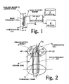
- FIG. 1 shows a block diagram of the NML apparatus
- FIG. 2 shows the general view of the NML sonde
- FIG. 3 shows the cross section of the NML sonde
- FIG. 4 shows the variations of the field of the radio frequency coil, the field of the compensating coil and the sum radio frequency field as functions of the distance from the narrow lateral surface of the magnet.
- FIG. 5 shows the experimental data obtained at a frequency of 500 kHz using a radio frequency coil 100 mm in diameter with 4 turns, inside which a magnet made of NdFeB of varying thickness and the same magnet with a shield made of various materials are inserted.
- Nuclear magnetic logging apparatus was designed as follows: it has as shown in FIG. 1 , a nuclear magnetic logging sonde 1 , matching device 2 , radio pulse generator 3 and receiver 4 .
- Nuclear magnetic logging sonde 1 comprises a long magnet made in the shape of a parallelepiped 5 (shown in FIGS. 1 , 2 , and 3 ) and magnetized perpendicular to its long axis and wide side.
- the magnet is inserted in cylindrical frame 6 (shown in FIGS. 2 , and 3 ), on which radio frequency coil 7 (shown in FIGS. 1 , 2 , and 3 ) is wound.
- the coil is wound in 120° symmetric sectors arranged opposite the wide side of magnet 5 .
- the turns of radio frequency coil 7 lie on the planes parallel to the narrow side of magnet 5 .
- Compensating coil 8 (shown in FIGS. 1 , 2 , and 3 ) with turns parallel to the turns of radio frequency coil 7 is wound on magnet 5 .
- the beginning of radio frequency coil 7 is connected to the first input of matching device 2 , while its end is connected to the end of compensating coil 8 .
- the beginning of the compensating coil 8 is connected to the common point of matching device 2 .
- the output of radio pulse generator 3 is connected to the second input of the matching device, while the output of the matching device is connected to the input of receiver 4 .
- the magnet is made of NdFeB in the shape of a parallelepiped 1000 mm long, 80 mm wide, with a narrow lateral side of 40 mm.
- the magnet 5 is magnetized perpendicular to the longitudinal axis and the wide lateral surface.
- a shield of copper sheet 0.5 mm thick is applied to the surface of the magnet and covers its lateral surfaces along its entire length.
- the radio frequency coil 7 is made of a glass cloth base laminate cylinder 800 mm long with an inner diameter of 100 mm and an outer diameter of 102 mm.
- the turns of the coil 7 are applied to the outer surface of the cylinder 6 along its length, in symmetric 120° sectors. The ends of the winding are also on the outside of the cylinder 6 .
- the radio frequency coil 7 is connected to the input of the matching device 2 .
- a magnet 5 is inserted inside the radio frequency coil 7 so that the turns of the coil 7 are opposite its wide lateral surface.
- the nuclear magnetic logging apparatus works as follows.
- Magnet 5 induces a plane-parallel static magnetic field with magnitude H 0 at a radial distance r p from the axis of the magnet.
- the field magnitude H 0 is constant over the entire circle with radius r p .
- the direction of this field differs at different points on the circle.
- Radio frequency coil 7 together with compensating coil 8 generates a sum plane-parallel radio frequency field H 1 , which has the same constant magnitude at radius r p .
- the direction of the radio frequency field H 1 is perpendicular to the field H 0 at each point on a circle of radius r p .
- FIG. 4 shows a graph of the RF field strength where the sum radio frequency field 10 consists of the field 11 created by radio frequency coil 7 and field 12 created by the compensating coil 8 . There is no radio frequency field in the area of the magnet 5 , and the field varies insignificantly in sensing zone 9 .
- FIG. 5 shows a representation wherein a shield made of a highly conductive material applied to the magnet surface can serve as the compensating coil 8 .
- the sum radio frequency field varies according to the same law as the sum radio frequency filed 10 discussed above.
- the change in the Q-factor of the radio frequency as a function of the material and width of the shield is shown in:
- the changes in the Q-factor are smallest material with resistivity less than 2.5 ⁇ 10 ⁇ 8 ohms ⁇ m is placed inside the coil 7 , and largest when a magnet made of NdFeB without a shield is placed inside the coil 7 .
- the radio frequency coil 7 will only sense the copper foil.
- the absence of a radio frequency field in the area of the magnet 5 makes it possible to use any materials for the magnet 5 , including conducting rare-earth materials, NdFeB for example. Since rare-earth magnets have significantly higher residual magnetization than ferrite, the NML sonde can have a smaller diameter but still retain the same sensing radius.
- a sonde for NML was tested in wellbores up to 4500 m deep at temperatures up to 120° C. It is possible to use the invention in high-temperature wellbores.
Landscapes
- Life Sciences & Earth Sciences (AREA)
- Physics & Mathematics (AREA)
- Remote Sensing (AREA)
- Engineering & Computer Science (AREA)
- Environmental & Geological Engineering (AREA)
- Geology (AREA)
- High Energy & Nuclear Physics (AREA)
- General Life Sciences & Earth Sciences (AREA)
- General Physics & Mathematics (AREA)
- Geophysics (AREA)
- Magnetic Resonance Imaging Apparatus (AREA)
- Geophysics And Detection Of Objects (AREA)
- Magnetic Treatment Devices (AREA)
- Measuring Magnetic Variables (AREA)
- Nitrogen Condensed Heterocyclic Rings (AREA)
Applications Claiming Priority (3)
| Application Number | Priority Date | Filing Date | Title |
|---|---|---|---|
| RU2001101813 | 2001-01-19 | ||
| RU2001101813/28A RU2181901C1 (ru) | 2001-01-19 | 2001-01-19 | Способ каротажа с использованием ядерно-магнитного резонанса и устройство для его осуществления |
| PCT/RU2001/000557 WO2002057809A1 (fr) | 2001-01-19 | 2001-12-20 | Procede de diagraphie utilisant la resonance magnetique nucleaire et dispositif correspondant |
Publications (2)
| Publication Number | Publication Date |
|---|---|
| US20040052116A1 US20040052116A1 (en) | 2004-03-18 |
| US7075298B2 true US7075298B2 (en) | 2006-07-11 |
Family
ID=20245061
Family Applications (1)
| Application Number | Title | Priority Date | Filing Date |
|---|---|---|---|
| US10/466,232 Expired - Lifetime US7075298B2 (en) | 2001-01-19 | 2001-12-20 | Method and apparatus for well logging using NMR with a long conductive rare-earth magnet and excitation compensation in the area of the long magnet |
Country Status (7)
| Country | Link |
|---|---|
| US (1) | US7075298B2 (de) |
| CA (1) | CA2432230C (de) |
| DE (1) | DE10197175B3 (de) |
| GB (1) | GB2387233B (de) |
| NO (1) | NO334392B1 (de) |
| RU (1) | RU2181901C1 (de) |
| WO (1) | WO2002057809A1 (de) |
Cited By (5)
| Publication number | Priority date | Publication date | Assignee | Title |
|---|---|---|---|---|
| US20060255799A1 (en) * | 2005-01-18 | 2006-11-16 | Baker Hughes Incorporated | Nuclear magnetic resonance tool using switchable source of static magnetic field |
| US20080061778A1 (en) * | 2006-09-08 | 2008-03-13 | Masaya Takahashi | Antenna coil for nmr probe and wire rod for same and nmr system |
| US20090066331A1 (en) * | 2007-09-10 | 2009-03-12 | University Of New Brunswick | Probe, system and method suitable for unilateral nuclear magnetic resonance |
| US20090289747A1 (en) * | 2008-03-28 | 2009-11-26 | Commissariat A L'energie Atomique | Magnetic nano-resonator |
| US20230145921A1 (en) * | 2021-11-05 | 2023-05-11 | Halliburton Energy Services, Inc. | Efficient Transmitter For Nuclear Magnetic Resonance Logging While Drilling |
Families Citing this family (4)
| Publication number | Priority date | Publication date | Assignee | Title |
|---|---|---|---|---|
| RU2181901C1 (ru) | 2001-01-19 | 2002-04-27 | Акционерное общество закрытого типа Научно-производственная фирма по геофизическим и геоэкологическим работам "КАРОТАЖ" | Способ каротажа с использованием ядерно-магнитного резонанса и устройство для его осуществления |
| US7164266B2 (en) | 2003-03-07 | 2007-01-16 | Precision Energy Services, Inc. | Nuclear magnetic resonance tool with conductive and non-conductive magnet assembly |
| RU2495458C2 (ru) * | 2012-01-11 | 2013-10-10 | Общество с Ограниченной Ответственностью "ТНГ-Групп" | Устройство ядерно-магнитного каротажа |
| CN114089426B (zh) * | 2021-05-26 | 2023-11-10 | 华北科技学院(中国煤矿安全技术培训中心) | 一种改进的u形螺线源瞬变电磁全空间定向探测方法 |
Citations (16)
| Publication number | Priority date | Publication date | Assignee | Title |
|---|---|---|---|---|
| US3667035A (en) | 1970-03-17 | 1972-05-30 | Texaco Development Corp | Nuclear magnetism logging |
| US4350955A (en) | 1980-10-10 | 1982-09-21 | The United States Of America As Represented By The United States Department Of Energy | Magnetic resonance apparatus |
| US4710713A (en) | 1986-03-11 | 1987-12-01 | Numar Corporation | Nuclear magnetic resonance sensing apparatus and techniques |
| US4717877A (en) | 1986-09-25 | 1988-01-05 | Numar Corporation | Nuclear magnetic resonance sensing apparatus and techniques |
| US5055787A (en) | 1986-08-27 | 1991-10-08 | Schlumberger Technology Corporation | Borehole measurement of NMR characteristics of earth formations |
| US5212447A (en) | 1990-12-03 | 1993-05-18 | Numar Corporation | Apparatus and technique for nmr diffusion measurement |
| EP0618458A2 (de) | 1993-04-01 | 1994-10-05 | Schlumberger Limited | Messapparat mittels magnetischer Kernresonanz |
| GB2325981A (en) | 1997-04-21 | 1998-12-09 | Baker Hughes Inc | Well-logging with measurement while drilling |
| WO2000014576A1 (en) * | 1998-09-09 | 2000-03-16 | Baker Hughes Incorporated | Apparatus and method for making nuclear magnetic measurements in a borehole |
| SU577498A1 (ru) | 1975-12-10 | 2000-04-20 | Государственный Геофизический Трест "Татнефтегеофизика" | Способ ядерного магнитного каротажа |
| GB2343521A (en) | 1998-11-05 | 2000-05-10 | Schlumberger Holdings | NMR logging while drilling tool |
| US6069479A (en) * | 1996-11-04 | 2000-05-30 | Western Atlas International, Inc. | Permanent magnet material composition and structure for eddy current suppression in a nuclear magnetic resonance sensing apparatus |
| US6118272A (en) | 1996-02-23 | 2000-09-12 | Western Atlas International, Inc. | Nuclear magnetic resonance apparatus and method |
| WO2001007937A1 (en) | 1999-07-27 | 2001-02-01 | Oxford Instruments Superconductivity Limited | Apparatus for drilling a borehole with a non-rotating sleeve comprising an nmr sensor |
| WO2002057809A1 (fr) | 2001-01-19 | 2002-07-25 | Joint Stock Company Of Closed Type Scientific And Industrial Firm On Geophysical And Geoecological Works 'karotazh', Npf 'karotazh' | Procede de diagraphie utilisant la resonance magnetique nucleaire et dispositif correspondant |
| US20040066194A1 (en) * | 2001-01-12 | 2004-04-08 | Slade Robert Andrew | Magnetic field generating assembly and method |
-
2001
- 2001-01-19 RU RU2001101813/28A patent/RU2181901C1/ru active
- 2001-12-20 WO PCT/RU2001/000557 patent/WO2002057809A1/ru not_active Application Discontinuation
- 2001-12-20 US US10/466,232 patent/US7075298B2/en not_active Expired - Lifetime
- 2001-12-20 CA CA2432230A patent/CA2432230C/en not_active Expired - Lifetime
- 2001-12-20 GB GB0311513A patent/GB2387233B/en not_active Expired - Fee Related
- 2001-12-20 DE DE10197175.3T patent/DE10197175B3/de not_active Expired - Fee Related
-
2003
- 2003-07-18 NO NO20033271A patent/NO334392B1/no not_active IP Right Cessation
Patent Citations (22)
| Publication number | Priority date | Publication date | Assignee | Title |
|---|---|---|---|---|
| US3667035A (en) | 1970-03-17 | 1972-05-30 | Texaco Development Corp | Nuclear magnetism logging |
| SU577498A1 (ru) | 1975-12-10 | 2000-04-20 | Государственный Геофизический Трест "Татнефтегеофизика" | Способ ядерного магнитного каротажа |
| US4350955A (en) | 1980-10-10 | 1982-09-21 | The United States Of America As Represented By The United States Department Of Energy | Magnetic resonance apparatus |
| US4710713A (en) | 1986-03-11 | 1987-12-01 | Numar Corporation | Nuclear magnetic resonance sensing apparatus and techniques |
| US5055787A (en) | 1986-08-27 | 1991-10-08 | Schlumberger Technology Corporation | Borehole measurement of NMR characteristics of earth formations |
| US4717877A (en) | 1986-09-25 | 1988-01-05 | Numar Corporation | Nuclear magnetic resonance sensing apparatus and techniques |
| US5212447A (en) | 1990-12-03 | 1993-05-18 | Numar Corporation | Apparatus and technique for nmr diffusion measurement |
| RU2104565C1 (ru) | 1990-12-03 | 1998-02-10 | Ньюмар Корпорейшн | Способы измерения диффузии посредством ядерного магнитного резонанса (варианты) |
| EP0618458A2 (de) | 1993-04-01 | 1994-10-05 | Schlumberger Limited | Messapparat mittels magnetischer Kernresonanz |
| US5376884A (en) * | 1993-04-01 | 1994-12-27 | Schlumberger Technology Corporation | Nuclear magnetic resonance measuring apparatus |
| US5486761A (en) * | 1993-04-01 | 1996-01-23 | Schlumberger Technology Corporation | Nuclear magnetic resonance measuring apparatus |
| US6118272A (en) | 1996-02-23 | 2000-09-12 | Western Atlas International, Inc. | Nuclear magnetic resonance apparatus and method |
| US6069479A (en) * | 1996-11-04 | 2000-05-30 | Western Atlas International, Inc. | Permanent magnet material composition and structure for eddy current suppression in a nuclear magnetic resonance sensing apparatus |
| GB2325981A (en) | 1997-04-21 | 1998-12-09 | Baker Hughes Inc | Well-logging with measurement while drilling |
| WO2000014576A1 (en) * | 1998-09-09 | 2000-03-16 | Baker Hughes Incorporated | Apparatus and method for making nuclear magnetic measurements in a borehole |
| US6163151A (en) * | 1998-09-09 | 2000-12-19 | Baker Hughes Incorporated | Apparatus and method for making nuclear magnetic measurements in a borehole |
| GB2343521A (en) | 1998-11-05 | 2000-05-10 | Schlumberger Holdings | NMR logging while drilling tool |
| WO2001007937A1 (en) | 1999-07-27 | 2001-02-01 | Oxford Instruments Superconductivity Limited | Apparatus for drilling a borehole with a non-rotating sleeve comprising an nmr sensor |
| US20040066194A1 (en) * | 2001-01-12 | 2004-04-08 | Slade Robert Andrew | Magnetic field generating assembly and method |
| WO2002057809A1 (fr) | 2001-01-19 | 2002-07-25 | Joint Stock Company Of Closed Type Scientific And Industrial Firm On Geophysical And Geoecological Works 'karotazh', Npf 'karotazh' | Procede de diagraphie utilisant la resonance magnetique nucleaire et dispositif correspondant |
| US20040052116A1 (en) * | 2001-01-19 | 2004-03-18 | Mityushin Evgeny M. | Method for well logging using nuclear magnetic resonance and device for carrying put said method |
| GB2387233B (en) | 2001-01-19 | 2005-05-25 | Joint Stock Company Of Closed | Method for well logging using nuclear magnetic resonance and device for carrying out said method |
Non-Patent Citations (3)
| Title |
|---|
| Dr. Susan Dewar, Patents Act 1977 Examination Report under Section 18(3), Jul. 23, 2004, 2 pages, The EuropeanPatent Office. |
| R M Grechishkin, L E Afanasteva, Yu G Pastushenkov and N N Maksimov, Analysis of a Linear Position Sensor With a Hall Effect Element, Meas. Sci. Technol. 5, 1994, pp. 853-860, JOP Publishing Ltd., Department of Physics, Tver, Russia. |
| R.N. Chandler, E.O. Drack, M.N. Miller, and M.G. Prammer, Improved Log Quality With a Dual-Frequency Pulsed NMR Tool, SPE International, Sep. 1994, pp. 23-35, SPE 28365 Presented at the 69th Annual Technical Conference and Exhibition, New Orleans, LA, U.S.A. |
Cited By (11)
| Publication number | Priority date | Publication date | Assignee | Title |
|---|---|---|---|---|
| US20060255799A1 (en) * | 2005-01-18 | 2006-11-16 | Baker Hughes Incorporated | Nuclear magnetic resonance tool using switchable source of static magnetic field |
| US7859260B2 (en) * | 2005-01-18 | 2010-12-28 | Baker Hughes Incorporated | Nuclear magnetic resonance tool using switchable source of static magnetic field |
| NO20090420L (no) * | 2006-07-27 | 2009-04-23 | Baker Hughes Inc | Kjernemagnetisk resonansverktoy som benytter svitsjbar kile for statisk magnetfelt |
| NO343027B1 (no) * | 2006-07-27 | 2018-10-08 | Baker Hughes A Ge Co Llc | Kjernemagnetisk resonansverktøy som benytter svitsjbar kilde for statisk magnetfelt |
| US20080061778A1 (en) * | 2006-09-08 | 2008-03-13 | Masaya Takahashi | Antenna coil for nmr probe and wire rod for same and nmr system |
| US20090066331A1 (en) * | 2007-09-10 | 2009-03-12 | University Of New Brunswick | Probe, system and method suitable for unilateral nuclear magnetic resonance |
| US7733091B2 (en) * | 2007-09-10 | 2010-06-08 | University Of New Brunswick | Probe, system and method suitable for unilateral nuclear magnetic resonance |
| US20090289747A1 (en) * | 2008-03-28 | 2009-11-26 | Commissariat A L'energie Atomique | Magnetic nano-resonator |
| US8310320B2 (en) * | 2008-03-28 | 2012-11-13 | Commissariat A L'energie Atomique | Magnetic nano-resonator |
| US20230145921A1 (en) * | 2021-11-05 | 2023-05-11 | Halliburton Energy Services, Inc. | Efficient Transmitter For Nuclear Magnetic Resonance Logging While Drilling |
| US11768311B2 (en) * | 2021-11-05 | 2023-09-26 | Halliburton Energy Services, Inc. | Efficient transmitter for nuclear magnetic resonance logging while drilling |
Also Published As
| Publication number | Publication date |
|---|---|
| NO20033271L (no) | 2003-09-15 |
| RU2181901C1 (ru) | 2002-04-27 |
| WO2002057809A1 (fr) | 2002-07-25 |
| GB2387233A8 (en) | 2003-10-20 |
| DE10197175T1 (de) | 2003-12-04 |
| NO334392B1 (no) | 2014-02-24 |
| CA2432230A1 (en) | 2002-07-25 |
| CA2432230C (en) | 2012-03-13 |
| GB2387233A (en) | 2003-10-08 |
| NO20033271D0 (no) | 2003-07-18 |
| DE10197175B3 (de) | 2015-10-15 |
| US20040052116A1 (en) | 2004-03-18 |
| GB0311513D0 (en) | 2003-06-25 |
| GB2387233B (en) | 2005-05-25 |
Similar Documents
| Publication | Publication Date | Title |
|---|---|---|
| US5712566A (en) | Nuclear magnetic resonance apparatus and method | |
| EP1642156B1 (de) | Systeme und verfahren zum nmr-logging | |
| US6348792B1 (en) | Side-looking NMR probe for oil well logging | |
| US6215304B1 (en) | NMR sensor | |
| US7859260B2 (en) | Nuclear magnetic resonance tool using switchable source of static magnetic field | |
| JPH07174862A (ja) | 開型磁気構造 | |
| US10082595B2 (en) | Ultra-slim nuclear magnetic resonance tool for oil well logging | |
| US5923167A (en) | Pulsed nuclear magnetism tool for formation evaluation while drilling | |
| US6452388B1 (en) | Method and apparatus of using soft non-ferritic magnetic material in a nuclear magnetic resonance probe | |
| US5959453A (en) | Radial NMR well logging apparatus and method | |
| US6781371B2 (en) | High vertical resolution antennas for NMR logging | |
| GB2324375A (en) | Longitudinal NMR well logging apparatus and method | |
| RU2367982C1 (ru) | Способ каротажа с использованием ядерно-магнитного резонанса и устройство для его осуществления | |
| KR900002467B1 (ko) | Nmr용 라디오 주파수 장 코일 | |
| US7075298B2 (en) | Method and apparatus for well logging using NMR with a long conductive rare-earth magnet and excitation compensation in the area of the long magnet | |
| US7084625B2 (en) | Method and apparatus of reducing ringing in a nuclear magnetic resonance probe | |
| RU2318224C2 (ru) | Азимутальная ямр-визуализация свойств горной породы из ствола скважины | |
| US6518755B2 (en) | Measurement technique and apparatus for high-resolution multi-volume NMR well logging | |
| RU2337436C2 (ru) | Усовершенствованные антенны для каротажа на основе ядерно-магнитного резонанса | |
| US5969527A (en) | Rf coil assembly | |
| WO1999008126A1 (en) | Magnetic field generating assembly for use in an nmr apparatus | |
| MXPA03006452A (es) | Metodo para diagrafia de sondeo utilizando resonancia magnetica nuclear y dispositivo para efectuar dicho metodo. | |
| GB2352300A (en) | NMR well logging using prepolarisation | |
| WO2003071310A1 (en) | Side-looking nmr probe for oil well logging | |
| GB2350685A (en) | NMR well-logging tool |
Legal Events
| Date | Code | Title | Description |
|---|---|---|---|
| AS | Assignment |
Owner name: KAROTAZH, RUSSIAN FEDERATION Free format text: ASSIGNMENT OF ASSIGNORS INTEREST;ASSIGNORS:MITYUSHIN, EVGENY M.;KHAMATDINOV, RAFIS T.;BARLYAEV, VADIM J.;REEL/FRAME:014690/0777 Effective date: 20030703 |
|
| STCF | Information on status: patent grant |
Free format text: PATENTED CASE |
|
| FEPP | Fee payment procedure |
Free format text: PAT HOLDER NO LONGER CLAIMS SMALL ENTITY STATUS, ENTITY STATUS SET TO UNDISCOUNTED (ORIGINAL EVENT CODE: STOL); ENTITY STATUS OF PATENT OWNER: LARGE ENTITY |
|
| REFU | Refund |
Free format text: REFUND - SURCHARGE, PETITION TO ACCEPT PYMT AFTER EXP, UNINTENTIONAL (ORIGINAL EVENT CODE: R2551); ENTITY STATUS OF PATENT OWNER: LARGE ENTITY |
|
| FPAY | Fee payment |
Year of fee payment: 4 |
|
| FPAY | Fee payment |
Year of fee payment: 8 |
|
| MAFP | Maintenance fee payment |
Free format text: PAYMENT OF MAINTENANCE FEE, 12TH YEAR, LARGE ENTITY (ORIGINAL EVENT CODE: M1553) Year of fee payment: 12 |