US7068835B1 - Data processing apparatus for processing a 3-dimensional data of an object and a method therefor - Google Patents
Data processing apparatus for processing a 3-dimensional data of an object and a method therefor Download PDFInfo
- Publication number
- US7068835B1 US7068835B1 US09/198,534 US19853498A US7068835B1 US 7068835 B1 US7068835 B1 US 7068835B1 US 19853498 A US19853498 A US 19853498A US 7068835 B1 US7068835 B1 US 7068835B1
- Authority
- US
- United States
- Prior art keywords
- dimensional
- data
- processing apparatus
- area
- data processing
- Prior art date
- Legal status (The legal status is an assumption and is not a legal conclusion. Google has not performed a legal analysis and makes no representation as to the accuracy of the status listed.)
- Expired - Fee Related, expires
Links
Images


Classifications
-
- G—PHYSICS
- G06—COMPUTING; CALCULATING OR COUNTING
- G06V—IMAGE OR VIDEO RECOGNITION OR UNDERSTANDING
- G06V20/00—Scenes; Scene-specific elements
- G06V20/60—Type of objects
- G06V20/64—Three-dimensional objects
- G06V20/647—Three-dimensional objects by matching two-dimensional images to three-dimensional objects
-
- G—PHYSICS
- G06—COMPUTING; CALCULATING OR COUNTING
- G06V—IMAGE OR VIDEO RECOGNITION OR UNDERSTANDING
- G06V10/00—Arrangements for image or video recognition or understanding
- G06V10/40—Extraction of image or video features
- G06V10/42—Global feature extraction by analysis of the whole pattern, e.g. using frequency domain transformations or autocorrelation
- G06V10/431—Frequency domain transformation; Autocorrelation
-
- G—PHYSICS
- G06—COMPUTING; CALCULATING OR COUNTING
- G06V—IMAGE OR VIDEO RECOGNITION OR UNDERSTANDING
- G06V40/00—Recognition of biometric, human-related or animal-related patterns in image or video data
- G06V40/10—Human or animal bodies, e.g. vehicle occupants or pedestrians; Body parts, e.g. hands
- G06V40/16—Human faces, e.g. facial parts, sketches or expressions
- G06V40/161—Detection; Localisation; Normalisation
Definitions
- This invention relates to a data processing apparatus for processing a 3-dimensional data for producing a model of an object existing and a method therefor, the apparatus and method being applied for, for example, production of a head model of a human being.
- a portable non-contact type 3-dimensional measuring apparatus (3-dimensional camera) has been commercialized and widely used for data entry into the CG system or CAD system, a physical measurement, and a robot visual recognition.
- the slit light projection method (light-section method) is generally known as the non-contact type measuring method, while the pattern light projection method, stereo view method and interference pattern method are well known as well.
- a kind of vending machine for producing a photo sticker of a customer's face on site has been attracting public attention.
- the customer throws in a coin for charge and takes a desired pose in front of a camera watching a monitor screen. Then, by carrying out a predetermined operation, a sheet containing the predetermined number of stickers is discharged into a discharge port.
- Most machines have a plurality of choices upon face photo shape, copy pattern and the like.
- the aforementioned 3-dimensional measuring apparatus various forms including a human being can be converted to data as easily as when taking a picture. Because this is the non-contact type, an object person does not feel inconvenience even when a physical measurement is carried out. Then, it can be considered that this 3-dimensional measuring apparatus is applied to the production of not a face photo but a face solid model. That is, by combining the 3-dimensional measuring apparatus with a 3-dimensional processing unit, it is possible to measure a human face and produce the solid model of an appropriate magnification on site.
- an element which is not discriminated from others in form viewpoints is not reproduced on the model.
- an iris in an eyeball are important elements which characterize the face, it is not discriminated from the white of the eye.
- An eyebrow drawn with an eyebrow pencil is also assimilated in the forehead.
- a person sometimes may feel a sense of disharmony on his or her solid model in which undulations of his or her face are reproduced faithfully. Sensing the undulation is affected by color as if the lips of warm color look swollen more than actually. Even if the form of the model is reproduced faithfully, a non-color model looks more flat than a familiar face. A model in which a certain face element is intentionally exaggerated is sometimes wanted or a model whose nose is raised more than a real nose is sometimes pleased.
- the front hair portion drooping over the forehead is an unnatural shape such as a thin plate projected from the forehead. Particularly if an end of the front hair portion is apart from the forehead, a bottom edge of the projected plate forms straight like a hood, thereby making the shape further unnatural.
- the front hair portion is reproduced by hollowing the projected plate portion, it is undesirable to reproduce the hair, the end of which floats, from the viewpoint of the mechanical strength of the model. Further, such a processing is very hard and takes much time to process.
- the hair portion of the human being may not be able to be measured accurately. That is, because black hair has a low reflectivity of the reference light, an amount of light received by a range finder becomes insufficient so that a measured value is likely to be missed. Further, an influence of the hair style is extreme. Therefore, upon production of a form model of a human head, there is a problem that the hair portion is reproduced incompletely or not reproduced.
- a purpose of the present invention is to make it possible to produce a model seen as natural by reflecting visual characteristics of an object on a form.
- Another purpose of the invention is to make it possible to produce a model exaggerated as required.
- the present invention comprises a modifying unit for modifying at least a part of 3-dimensional form data with reference to 2-dimensional image data obtained by photographing an object.
- the modifying unit extracts a specified area from the 2-dimensional image data according to a setting condition and modifies a part of the 3-dimensional form data corresponding to the specified area.
- a model is produced.
- the object for photographing for example, the human head is used.
- the specified area corresponds to at least one of the hair, forehead, eyebrows, eyes, irises, and lips.
- a distance image refers to a group of picture elements, the value of which indicates a distance and distance distribution is expressed by the picture element value therein. Because the distance image can be handled in the same manner as the 2-dimensional image upon analysis of the spatial frequency, the 3-dimensional unevenness can be analyzed without carrying out 3-dimensional coordinate operation by analysis of the spatial frequency of the distance image.
- the distance image and 2-dimensional image do not necessarily have to be visualized.
- the image mentioned here refers to a concept including a image data.
- Various processings according to the present invention can be achieved by a hardware circuit using various electronic devices, computer or microprocessor for executing a program or a combination thereof.
- a milling machine and other cutting machines such as a laminated forming machine, laser beam machine, molding machine, and electrical discharge machine may be used.
- FIG. 1 is an appearance of a solid model production apparatus according to a first embodiment.
- FIG. 2 is a diagram showing a state of use of the solid model production apparatus.
- FIG. 3 is a plane view of an operation panel.
- FIG. 4 is a block diagram showing the solid model production apparatus in views of the function.
- FIG. 5 is a perspective view showing an example of a processing system mechanism.
- FIG. 6 is a schematic view for extraction of face elements.
- FIG. 7 is a schematic view for partial data modification.
- FIG. 8 is a flow chart showing an outlined operation.
- FIG. 9 is a flow chart showing a content of data processing at step # 20 of FIG. 8 .
- FIG. 10 is a flow chart showing a content of the partial modifying processing at step # 230 of FIG. 9 .
- FIGS. 11(A) and 11(B) are diagrams for explaining a specified procedure for the hair portion in a second embodiment.
- FIG. 12 is a schematic view for extracting hair wave line information.
- FIG. 13 is a schematic view for classification of the hair wave line.
- FIG. 14 is a diagram showing an example of setting a striped pattern.
- FIG. 15 is a schematic view of partial modification on a form model.
- FIG. 16 is a flow chart showing a content of the second embodiment about the partial modifying processing at step # 230 of FIG. 9 .
- FIG. 17 is a flow chart showing extracting processing of the hair portion at step # 1110 of FIG. 16 .
- FIGS. 18(A) and 18(B) are diagrams showing other example of a method for specifying the hair portion.
- FIG. 19 is a flow chart showing extracting processing of the hair portion corresponding to FIG. 18 .
- FIG. 20 is a diagram showing steps for selecting a modifying object portion according to a third embodiment.
- FIG. 21 is a diagram showing a procedure for partial modification of the form model.
- FIG. 22 is a diagram showing a procedure for partial modification of the form model.
- FIG. 23 is a flow chart showing a content of the third embodiment about the partial modifying processing at step # 230 of FIG. 9 .
- FIG. 24 is an appearance of the solid model production apparatus according to a fourth embodiment.
- FIG. 25 is a block diagram showing the solid model production apparatus of the fourth embodiment in viewpoints of the function.
- FIG. 26 is a diagram showing schematically a camera allocation for 2-dimensional photographing.
- FIGS. 27(A) and 27(B) are diagrams for explaining a procedure for modeling according to the 2-dimensional image.
- FIG. 28 is a diagram for explaining a procedure for modeling according to the 2-dimensional image.
- FIG. 29 is a diagram showing schematically synthesis of the form models.
- FIG. 30 is a flow chart showing a content of the fourth embodiment about the partial modifying processing at step # 230 of FIG. 9 .
- FIG. 31 is a diagram schematically showing an estimation of a head skin face.
- FIG. 32 is a flow chart showing an example of a production procedure on a head skin face form model.
- FIG. 33 is a diagram showing a conventional problem.
- a portion necessary to be modified is specified based on 2-dimensional photograph information of an object or both the 2-dimensional photograph information and a distance image obtained by 3-dimensional measurement.
- a model which reflects a visual characteristic of the specified portion is generated.
- a model in which a local portion is stressed is generated. The positions of, for example, the eyes and eyeball are expressed in each form. The eyebrow drawn by an eyebrow pencil is also expressed in a form. The undulations of the nose and lips are stressed.
- FIG. 1 is an appearance of a solid model production apparatus according to a first embodiment.
- a 3-dimensional model production apparatus 1 has a function for measuring a form of an object and processing material just on site according to its measuring data, and is used as an automatic vending machine for selling a product imitating the face of a customer.
- the product is a solid model in which a face model projects from a plate of a predetermined shape (e.g., square). That plate (background portion) can be provided with a specific undulating pattern. If an appropriate metal fixture is attached to such a product, it is available as an accessory such as a pendant, broach and key holder. It is permissible to preliminarily attach such a metal fixture to a material.
- a light projection window 12 and a light receiving window 14 for optical type 3-dimensional measuring and a display 16 for a customer to confirm his or her pose are provided on a front surface of an upper half portion of a case 10 substantially as high as a man.
- the light receiving window 14 is used for 2-dimensional color photographing.
- a lower half portion of the case 10 is projected forward compared to the upper half portion and an operation panel 18 is provided on its upper surface.
- a product take-out port 20 is provided on a front panel of the lower half portion.
- FIG. 2 is a diagram showing a state of use of the solid model production apparatus.
- a background sheet 2 such as a sheet colored blue is disposed in front of the solid model production apparatus 1 .
- a customer 3 stands facing the solid model production apparatus 1 with the background sheet 2 in the back and throws in coins for charge. Then, if the customer 3 performs start operations, the solid model production apparatus 1 measures a form of an object existing within a specified range of the front and displays a 3-dimensional form model (e.g., a surface model) indicating a measuring result. If the customer 3 performs confirmative operations to make sure determining of a composition, the solid model production apparatus 1 starts 3-dimensional processing according to the measuring result. A product is completed in a few minutes. The customer 3 picks up the product from the product take-out port 20 .
- a 3-dimensional form model e.g., a surface model
- FIG. 3 is a plane view of an operation panel.
- An operation panel 18 shown in FIG. 3 comprises a start button 181 , a confirmation button 182 , a cancel button 183 , a joy stick 184 , and a coin slot 185 .
- the start button 181 is a start operation means and the confirmation button 182 is a confirmative operation means.
- the joy stick 184 is used for instruction of a change in the composition of a model.
- a rotation processing for the 3-dimensional form model is carried out according to a pan operation for inclining the joy stick 184 to the right and left, tilt operation for tilting it relative to a vertical direction and roll operation for rotating a knob, and a processing result is indicated each time of the operations.
- the cancel button 183 is an operation means for instructing a remeasurement when the customer 3 is not satisfied with the displayed 3-dimensional form model. However, the effective frequency of use of the cancel button 183 is set and the remeasurement cannot be instructed without any limit.
- FIG. 4 is a block diagram showing the solid model production apparatus in views of the function.
- the solid model production apparatus 1 comprises a modeling system 1 A for generating a 3-dimensional form model of a product size and a processing system 1 B for embodying the 3-dimensional form model.
- the modeling system 1 A includes a photographing system 30 for converting appearance information of the customer 3 as an original object to digital data.
- the photographing system 30 includes a 3-dimensional measuring unit 34 for converting form information to data by the slit light projection method, a 2-dimensional photographing unit 36 for converting color information to data, and a controller 38 . It is permissible to use other method for the 3-dimensional measuring instead of the slit light projection method.
- a form data DS which is measuring information by the 3-dimensional measuring unit 34 and color image data DC which is photographing information by the 2-dimensional photographing unit 36 are input to a data processing unit 40 .
- the 3-dimensional input device is composed as disclosed in Japanese Patent Laid-Open (A) No. 9-145319, the 2-dimensional photographing and 3-dimensional measuring on the same point can be easily performed, so that the position matching can be executed more easily.
- the data processing unit 40 includes an image processing circuit (not shown) and carries out various data processing including a data modification peculiar to this embodiment.
- a controller 42 of the data processing unit 40 conducts an entire control on the solid model production apparatus 1 and sends an appropriate instruction to the controller 38 of the photographing system 30 and a controller 76 of the processing system 1 B.
- the display 16 and an operating input system 80 are connected to this controller 42 .
- the operating input system 80 comprises the aforementioned operation panel 18 and a charge receiving mechanism.
- the processing system 1 B comprises a processing unit 72 for cutting material such as resin block, a material supply unit 74 for supplying material to a processing position and transporting a processed product to the product take-out port 20 , a controller 76 and a take-out port sensor 78 .
- a detection signal of the take-out port sensor 78 is input to the controller 42 .
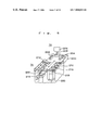
- FIG. 5 is a perspective view showing an example of a processing system mechanism.
- the material supply unit 74 includes a stock portion 210 for storing materials of 8 types of forms.
- Storage space is provided on each of both sides of a straight-line transportation path 212 and four elevators 220 are arranged in each storage space along the transportation path 212 .
- a plurality of materials of the same type are stacked on each elevator 220 and the elevator 220 is lifted upward/downward so as to locate the topmost material at a predetermined height. If a kind of material suitable for a model to be produced is specified, the specified material is carried as a work 216 to the transportation path 212 from the storage space by a push rod 218 .
- the work 216 on the transportation path 212 is sent to a table 200 of the processing unit 72 by a chuck-provided transportation rod 214 .
- the work 216 is fixed to the table 200 by two stoppers 202 and a clamp jig 204 . Then, the work 216 is cut by a blade 208 mounted on a rotary shaft 206 capable of moving vertically, to the right/left and up/down.
- the work 216 is nipped by the chuck provided at an end of the transportation rod 214 , carried to a discharge end portion of the transportion path 212 thereby and sent into a discharge port 222 .
- the work 216 may be moved from the table 200 to the discharge port 222 through a slide.
- the structure of the processing system 1 B is not restricted to the example mentioned above.
- the number of the elevators can be reduced.
- the model may be produced by laminated forming method (including optical forming method), laser processing (heat processing) and molding (e.g., pressure molding).
- the material shape it is permissible to use a structure allowing the customer 3 to select a desired shape, or a structure allowing to automatically select a face model requiring the shortest time for processing from among a plurality of materials roughly molded to standard faces preliminarily.
- data modification for automatically modifying a 3-dimensional form model obtained by 3-dimensional measuring by using color photographing information of the face is carried out by the data processing unit 40 to produce a face model having undulations expressing the iris and eyebrow and having the nose and lips stressed.
- FIG. 6 is a schematic view for extracting face elements.
- the data processing unit 40 extracts specific face element areas from a 2-dimensional image G 2 expressed by color image data DC and from a distance data G 3 expressed by form data DS.
- the eyebrows, irises, and lips are extracted from the 2-dimensional image G 2 , because the undulations of these face elements are minute and difficult to be extracted from the distance data G 3 .
- the nose and neck are extracted from the distance data G 3 , because the nose has a similar color as its surroundings (e.g., cheek) so that it is difficult to extract from the 2-dimensional image G 2 . The same can be said about the neck.
- the extraction from the 2-dimensional image G 2 is carried out in such manner as follows:
- characteristic areas a 1 , a 2 , a 3 , and a 4 corresponding to the eyebrows, eyes, irises, and lips are selected.
- a boundary between the red lip and shade and a boundary between the shade and skin color jaw are extracted, and a virtual line passing through an intermediate portion between these boundaries is obtained and this virtual line is adopted as a part of the contour of the lower lip. That is, as for the shade portion, its area is divided with reference to the color information of the surroundings.
- the extraction from the distance data G 3 is carried out in such manner as follows:
- the distance data G 3 is divided to areas within the same distance range.
- FIG. 7 shows a schematic diagram of partial data modification.
- the characteristic areas a 1 –a 4 of class 1 extracted from the 2-dimensional image G 2 in the manner above and the characteristic areas b 1 and b 2 of class 2 extracted from the distance image G 3 are set as objects for modification.
- Each object Up for modification is subjected to modification of a predetermined extent.
- the modification is carried out in such manner as follows:
- a mesh M perpendicular to the line of vision of a camera is projected over an object Up for modification and positions on which each lattice point of the mesh M is projected of the object Up for modification are assumed to be a sampling point p.
- a modificative vector v having a set length, which directs toward a camera with respect to the sampling point p and is perpendicular to a model surface is calculated. The length of the modificative vector v is set depending on each face element. For example, the length of the eyebrow is longer that that of the eye.
- ⁇ circle around (3) ⁇ An intersection (called a contour point) q between the mesh M and contour of the modification object Up is obtained.
- the modification object portion Up is swollen so that, for example, the positions of the eyes and irises are expressed with their particular shapes.
- the same is applied to eyebrows drawn with an eyebrow pencil.
- the undulations of the nose and lips are stressed.
- the neck is assimilated with the background. Because the position of the contour point q is not changed, continuity of the surface among the eyebrow, irises and their surroundings is maintained.
- FIG. 8 is a flow chart showing an outlined operation.
- the 2-dimensional photographing and a display of a photographing result are repeated (# 10 , # 12 , and # 14 ).
- a guide message is displayed periodically. If a fee is thrown in and the start button 181 is pressed, the 2-dimensional photographing is carried out newly and the 3-dimensional measuring is carried out (# 16 and # 18 ). A predetermined data processing is carried out (# 20 ) and the obtained 3-dimensional form model is displayed (# 22 ). At this time, a known graphic technique such as providing with a shade is used to make a good show. Then, this processing waits for a next instruction. However, the waiting time is limited and if the limit time is passed, it is deemed that a recognizing operation has been performed.
- the joy stick 184 If the joy stick 184 is operated, the 3-dimensional model is rotated depending on the operation as described above (# 24 and # 38 ). If the cancel button 183 is pressed, the operation returns to standby period operation (# 40 and # 10 ). However, in this case, the customer 3 does not have to thrown in a coin for charge, and only if the start button 181 is pressed, the remeasurement is carried out.
- processing control data is generated with reference to processing condition database based on the 3-dimensional form model (# 28 ). Then, material processing is carried out (# 30 ).
- FIG. 9 indicates a detailed content of the data processing at step # 20 described above.
- the following processings including the data modification for inducing a partial undulation as described above, shortening of processing time and compression of the depth direction for intentionally flattening are carried out.
- smoothing processing is carried out to remove abnormal data due to noise and avoid an excessive representation of fine unevenness (# 200 ).
- Resampling processing is carried out (# 210 ). This is a processing for converting to data arranged by the lattice points having the same interval projected in parallel from a certain direction to make input data face properly in the processing direction.
- a data missing portion is interpolated (# 220 ).
- the interpolation method linear interpolation, weighted interpolation and other various methods are available. For example, all the portions missing data are replaced with fixed values (simple interpolation).
- the fixed value a set value, a minimum height and an average value of face peripheral positions can be considered. If the data missing portion is completely surrounded by effective data portion, it is linearly interpolated with surrounding data. In case it is estimated that no accurate data can be obtained by optical 3-dimensional measuring because of the character of an object such as the black eyebrow and hair in the human face, that data may be replaced with existing 3-dimensional form data.
- the standard model for the face (front half face of the head) is prepared and for the data missing portion, the standard model data the position and size of which are adjusted is used.
- the adjustment of the standard model is carried out in a following procedure.
- the eyes and mouth are extracted from the 2-dimensional image and the positions of these three reference points are calculated.
- the linear conversion of the standard model is carried out to make the respective reference points of the standard model coincide with actually measured form model.
- Such a synthesis can be applied to any portion as well as the missing portion of the face.
- the eyebrows and irises are embodied and data modification for stressing the lips and nose particular to this embodiment is carried out (# 230 ). It is permissible to only embody the eyebrows and irises without stressing the lips and nose. It is possible to provide with a mode selection function so that the customer 3 or unit controller can select whether or not the data modification should be carried out and if it is done, which portion (face element) should be modified.
- height compression processing is carried out to shorten the 3-dimensional form model in the depth direction (# 240 ). That is, a difference in height in the depth direction is reduced so as to shorten processing time.
- a flat model is suitable for application to the pendant and medal.
- both equal compression and unequal compression are applicable and they can be selected for each part.
- a background portion of the 3-dimensional form model is detected (# 250 ). This is a pretreatment for modifying the background portion. If a result of color discrimination of the 2-dimensional image is applied with the background of the customer as a blue back, detection of the background is made easily and securely.
- Background conversion in which the background portion is replaced with other data is carried out (# 260 ).
- the replacement data may be flat data or solid data expressing pattern of flowers and tree or geometric pattern.
- Size adjustment for making a real 3-dimensional form model to a product size is carried out (# 270 ). Further, resolution conversion for making a data quantity coincide with an accuracy of the processing unit 72 is carried-out (# 280 ). In this processing, a mesh of a predetermined lattice interval is projected so as to resample at the lattice points. The projection direction is fixed in a perpendicular direction upon processing.
- resolution conversion data number conversion
- position matching for moving the home position of coordinate so that the reference position of the 3-dimensional form model coincides with the processing reference position is carried out (# 290 ).
- a cutting amount is calculated by comparing the unevenness of the 3-dimensional form model obtained by the above processing with the predetermined unevenness.
- FIG. 10 shows a detailed content of partial modifying processing of step # 230 described above.
- the class 1 face elements difficult to discriminate such as the eyebrows and irises are extracted from the 2-dimentional image G 2 (# 1010 ).
- the class 2 face elements difficult to discriminate by the color such as the nose and neck are extracted from the distance image G 3 (# 1020 ). Any of the class 1 and class 2 may be extracted first and both of them may be extracted in parallel at the same time.
- the modifying object portion Up is set in the 3-dimensional form model (# 1030 ), the mesh M is projected and a modificative vector v is calculated (# 1040 and # 1050 ). Further, an intersection (contour point) q between the contour of the modifying object portion Up and mesh M is obtained (# 1060 ). Any of the modifying object portion Up and contour point q may be obtained first and arithmetic operation for obtaining these can be carried out in parallel.
- a plane including the front end point p 2 of the modificative vector v and contour point q is obtained as a modifying portion model (# 1070 ) and the obtained plane is synthesized with its original 3-dimensional form model (# 1080 ).
- visual characteristics of an object can be reflected on a form so that a model natural to see can be produced. Further, as required, an modified model can be produced.
- the solid model production apparatus 1 presumed to be used as a vending machine is exemplified
- the data processing according to this invention is not related to which production of a model is charged or non charged.
- the model size is not restricted to a reduced size, but a real size or an enlarged size may be applied.
- An original object may be living thing other than the human being, such as dogs or cats.
- a particular portion of the form model is extracted by analysis of spatial frequency of the referred image. Then, that particular portion is subjected to data processing. For example, a hair portion is extracted from a human form model and an undulation pattern expressing hair texture is attached thereto.
- the data processing includes modification, substitution and texture mapping.
- the hair portion can be specified more securely than the analysis of the color information generally carried out. That is, because the hair color varies and the skin color also varies, the reliability of discrimination between the hair and face is very difficult. On the contrary, a difference in frequency distribution meaning that the hair portion contains more high frequency components than the face portion is an eternal fact and therefore, an error in discrimination is difficult to occur under various conditions.
- data modification for automatically modifying the 3-dimensional form model obtained by 3-dimensional measuring is carried out by the data processing unit 40 .
- the modification is a processing for attaching a registered striped undulation pattern to the hair portion of the 3-dimensional form model, that is, providing with a number of grooves or striped undulations.
- the data processing unit 40 analyzes a distribution of the spatial frequency on the 3-dimensional measuring information (distance image) or color photographing information to specify the hair portion of an object for modification.
- hair wave line of each portion is determined according to the color photographing information and corresponding to the result, the hair portion is divided and then an optimum undulation pattern is attached to each divided area. It is permissible to discriminate a hair style depending on the shape of the hair portion and attach a predetermined undulation pattern evenly irrespective of the real hair wave line.
- FIGS. 11(A) and 11(B) show a procedure for specifying the hair portion.
- the distance image G 10 of the head obtained by 3-dimensional measuring on the customer 3 is divided finely to lattices.
- 2-dimensional Fourier transformation is carried out for each segment e divided finely so as to obtain the spatial frequency spectrum.
- FIG. 11(B) integration of spectrum strength is carried out about a range (shadow portion of figure) in the high frequency side relative to the set frequency f 1 .
- the segment e in which an integrated value is above the set value is determined to correspond to the hair portion h 1 .
- a set of the segments e determined like this is specified to be the hair portion.
- FIG. 12 shows a schematic view for extracting hair wave line information.
- the data processing unit 40 extracts a portion corresponding to the hair portion h 1 of the distance image G 10 specified in the above manner from the 2-dimensional image expressed by the color image data DC, as the hair area.
- the hair wave line information is extracted in such manner as follows:
- Differential treatment of first order is executed about the hair area of the 2-dimensional image so as to detect an edge.
- the edge detecting image G 21 is binarized within a predetermined threshold.
- FIG. 13 shows a schematic view on classification of the hair directions.
- the data processing unit 40 scans the 2-dimensional image G 26 from which the hair wave line information has been extracted in the above manner while carrying out matching between the line segment Lg indicating the wave line and a registered mask pattern m 1 – 8 . As a result, a mask pattern having the most coinciding picture elements is determined to be a mask pattern of that portion.
- the wave line is classified to any direction of the mask patterns m 1 – 8 .
- FIG. 14 is a diagram showing an example of setting a striped pattern.
- the 2-dimensional image G 26 of the hair portion is segmented corresponding to a distribution of the mask pattern and the respective segments a 1 –a 5 are filled with each corresponding mask pattern. That is, a hair pattern is set.
- FIG. 15 is a schematic view of partial modification on a form model.
- the image G 27 filled with the hair pattern is projected to a form model U and then the form model U is partially modified so as to provide with a groove g having a predetermined depth corresponding to the hair pattern hp.
- a striped undulation looking like the hair is attached to the hair portion Uh of the form model U so as to express hair texture.
- the section of the groove g may be any shape such as U-shape, V-shape and rectangular. Further, the section thereof may be parabolic arch, just like shaved with an engraving knife having a round head. Instead of providing with the groove g, it is permissible to make that portion swell like the stripe.
- the section of the swollen portion may be set in any shape like the groove.
- An entire operation of the second embodiment is like the main flow chart of FIG. 8 .
- step # 230 of the flow chart of FIG. 9 partial modifying processing is performed.
- data modification for attaching striped undulation to the hair portion is carried out to express hair texture.
- FIG. 16 indicates a detailed content of the partial modifying processing.
- a hair portion is extracted from the distance image G 10 (# 1110 ).
- a series of processings such as edge detection, noise removal, making into fine line, segmentation of line, and removal of loop are carried out so as to extract the hair wave line information (# 1120 –# 1160 ).
- the wave line is classified depending on matching with the mask pattern (# 1170 ), the hair portion of the 2-dimensional image is segmented (# 1180 ), and each segment is filled with an appropriate hair pattern (# 1190 ).
- the hair pattern is projected to the form model (# 1200 ) and the form model is partially modified so as to produce an undulating surface looking like the hair (# 1210 ).
- FIG. 17 shows an extracting processing for extracting the hair portion.
- Each segment e produced by dividing the distance image G 10 of the head of the customer 3 is subjected to 2-dimensional Fourier transformation (# 3011 ). Integral operation is carried out to obtain an amount of component on higher frequency side relative to the set frequency f 1 (# 3012 ). Then, the segment e in which the integral value is more than the set value is determined to correspond to the hair portion (# 3013 ).
- FIGS. 18(A) and 18(B) show other example for specifying the hair portion.
- the 2-dimensional image G 20 of the head obtained by color photographing on the customer 3 is divided to lattices. Each segment e produced by that division is subjected to 2-dimensional Fourier transformation so as to obtain the spatial frequency spectrum.
- a range on the higher frequency side (shadow portion of the figure) relative to the set frequency f 2 is subjected to integral operation about the spectrum intensity. Then, the segment e in which the integral value is more than the set value is determined to correspond to the hair portion.
- a set of the segments e determined like this is specified to be the hair portion.
- FIG. 19 shows a processing for extracting the hair portion corresponding to FIGS. 18(A) and 18(B) .
- the color 2-dimensional image G 20 is transformed to gray image of 256 grades (# 3020 ).
- the obtained gray image is divided to lattices and each segment e is subjected to Fourier transformation (# 3021 ). Integral operation is carried out so as to obtain an amount of component on the higher frequency side relative to the set frequency f 2 (# 3022 ). Then, the segment e in which the integral value is above the set value is determined to correspond to the hair portion (# 3023 ).
- the hair portion is specified at a high precision thereby obtaining hair texture, so that a model of the human being head natural to see can be produced.
- the wave line directly from the 3-dimensional form instead of extracting the hair wave line information from the 2-dimensional image. That is, the normal vector is obtained at an appropriate sampling density on the model surface and a area in which the normal vector direction changes is regarded as a swollen portion indicating the direction of the wave line.
- the striped pattern is attached as the hair line pattern, a circular pattern may be attached instead depending on the hair style.
- a portion which may produce an extreme undulation in case non-contact 3-dimensional measuring is carried out is specified and that portion is smoothed.
- a processing for smoothing the front hair portion is carried out. That is, according to this embodiment, to produce a model of the human being head having the hair natural to see, the data modification of automatically modifying the form model obtained by 3-dimensional measuring with reference to the color photographing information of the head portion (including the face) is carried out by the data processing unit 40 .
- the modification is a processing for smoothing the front hair portion of the form model appropriately so as to eliminate a feeling of disharmony.
- the color photographing information is used for specifying the hair portion.
- FIG. 20 shows steps for selecting a modifying object portion.
- the data processing unit 40 extracts a border C 1 between the face and hair portion from the 2-dimensional image G 2 expressed by the color image data DC.
- the extracting procedure is as follows:
- an area of the front hair covering the forehead is estimated in such manner as follows:
- a 2-dimensional image G 2 is divided to mosaic.
- An area surrounded by the border C 1 and a portion of the border C 2 above the border C 1 is regarded as an attention area E.
- the reason for this procedure is that if an area inside the border C 2 is regarded as the modifying range, the lower side becomes a straight line which is unnatural as a form of the hair portion.
- FIGS. 21 and 22 show a procedure for partial modification of the form model.
- XYZ Cartesian coordinates are applied to the form model specified by the form data DS.
- the back/forth direction of the face is regarded as X axis
- the right/left direction thereof is regarded as Y axis
- the vertical direction thereof is regarded as Z axis.
- X axis a direction from the form model U toward a line of vision upon the 3-dimensional measuring is regarded as positive direction.
- Y axis a direction from the left to the right is regarded as positive direction.
- Z axis a direction from down to up is regarded as positive direction.
- a point Z 1 on which a bottom end (border C 1 ) of the attention area E of the 2-dimensional image G 2 is projected is regarded as a bottom end of the modification range and a point Z 2 on which a upper end (contour C 2 ) of the attention area E is projected is regarded as a upper end of the modification range.
- a curve between the point Z 1 and point Z 2 is regarded as original curve H 10 .
- the front hair portion of the form model U is modified so as to gradually extend from the forehead.
- the same processing is repeated at every position with a specified interval including both ends in the Y direction of the attention area E so as to obtain a plurality of cut surfaces. By interpolating along these cut surfaces, a curve continuous in the Y direction is obtained.
- a model provided with a natural feeling in which the front hair portion is not projected steely like a hood but is swollen mildly from the forehead is produced.
- the front hair droops sparsely, as shown in FIG. 33 , the front hair is expressed by an undulated surface in which the back/forth (X direction) position changes continuously and smoothly instead of it that sheet-like protrusions are arranged in order. That is, about the front hair portion, the undulation of the form model U is smoothed.
- a point Y 1 apart from the point Y 2 inside of the attention area E with a predetermined distance is regarded as the other end of the modification range.
- the distance from the point Y 2 to the point Y 1 is selected so that the undulation of the model surface is natural.
- the distance is about 1/10 relative to the face width.
- ⁇ circle around (4) ⁇ Of the contour of the cut surface of the form model U, a curve between the point Y 1 and point Y 2 is regarded as the original curve H 20 .
- the step between the right/left ends of the front hair portion and forehead is smoothed so that a form model in which the forehead is mildly continuous with the front hair portion is obtained.
- An entire operation of the third embodiment is as shown by a main flow chart of FIG. 8 .
- step # 230 of the flow chart of FIG. 9 partial modifying processing is performed.
- FIG. 23 shows a detailed content of the partial modifying processing.
- FIG. 23 is a flow chart showing a content of the third embodiment about the partial modifying processing at step # 230 of FIG. 9 .
- the 2-dimensional image G 2 it is possible to divide the 2-dimensional image G 2 to fine portions, detect the edge of each segment and extract the front hair portion by determining a magnitude of edge density.
- a segment corresponding to the front hair portion has a larger edge density than the other portions.
- This embodiment is applicable to all objects having a linear portion floating from a base portion as well as the hair of a living thing.
- the detection of the hair area may be carried out base on the 3-dimensional form data as well as based on the 2-dimensional image. For example, by analyzing the spatial frequency of the form data, the high frequency component is detected as the hair portion. Then, it is permissible to carry out the above smoothing on a portion of a predetermined width in the vicinity of a border with the face or a portion having a large undulation.
- a portion having a particular color of an object is modeled as a simple way by using plural different 2-dimensional photographing informations obtained from different photographing angles relative to the object. For example, an area in which the setting condition of color information is satisfied is extracted from each of plural 2-dimensional images obtained by photographing an object from different positions and coordinates of positions on the object corresponding to each contour of extracted plural areas in virtual space are calculated so as to produce a form model of a portion satisfying the setting condition of that object.
- plural 2-dimensional images obtained by photographing an object from different positions so that the lines of vision intersect with each other at a single point are disposed in virtual space under an adjusted image size in which the reduction ratio of the object coincides with each other, in such a manner that the centers thereof coincide and the angle of each disposition meets the line of vision and direction of angle of view. Then, a relative position of the contour of an area satisfying the setting condition of the color information extracted from each 2-dimensional image is calculated.
- the center of an image refers to a position of a picture element corresponding to the line of vision upon photographing.
- FIG. 24 is an appearance of the solid model production apparatus according to a fourth embodiment.
- a front face of a upper half portion of the case 10 has three light receiving windows 14 , 15 A, and 15 B.
- Optical 3-dimensional measuring is carried out using the light projection window 12 and light receiving window 14 .
- Two light receiving windows 15 A and 15 B are used for 2-dimensional color photographing in an oblique direction particular to this embodiment.
- the other structure of the solid model production apparatus 1 d is the same as the solid model production apparatus 1 of the first embodiment. Therefore, in a following description, the same reference numerals are attached to components having the same function as the solid model production apparatus 1 and a description thereof is omitted or simplified.
- FIG. 25 is a block diagram showing the solid model production apparatus of the fourth embodiment in viewpoints of the function.
- the solid model production apparatus 1 d comprises a modeling system 1 A for generating a 3-dimensional form model of a model size and a processing system 1 B for embodying the 3-dimensional form model.
- the modeling system 1 A comprises a photographing system 30 for converting appearance information of the customer 3 of an original object to digital data.
- the photographing system 30 comprises a 3-dimensional measuring unit 34 for converting form information to digital data by slit light projecting method, three 2-dimensional photographing units (main camera 36 , auxiliary cameras 37 L and 37 R) for converting color information to digital data and a controller 38 .
- Other optical method may be used for the 3-dimensional measuring instead of the slit light projecting method.
- Form data DS which is measuring information by the 3-dimensional measuring unit 34
- color image data DC 1 which is photographing information by the main camera 36
- color image data DC 2 and DC 3 which are photographing information by the respective auxiliary cameras 37 L and 37 R are input to the data processing unit 40 .
- the data processing unit 40 contains an image processing circuit (not shown), which carries out various data processings including data modification particular to this embodiment. That is, the data processing unit 40 is a means for generating the second form data of this invention and also a means for synthesizing the first and second form data.
- the controller 42 of the data processing unit 40 performs the entire control on the solid model production apparatus 1 d so as to supply the controller 38 of the photographing system 30 and controller 76 of the processing system 1 B with an appropriate instruction.
- This controller 42 is connected to the display 16 and operating input system 80 .
- the operating input system 80 includes the aforementioned operation panel 18 and fee receiving mechanism.
- the processing system 1 B comprises processing unit 72 for cutting material such as resin block, material supply unit 74 for supplying material to a processing position and carrying a processed product to the product take-out port 20 , controller 76 and take-out port sensor 78 .
- a detection signal of the take-out port sensor 78 is input to the controller 42 .
- data modification for automatically modifying the 3-dimensional form model obtained by 3-dimensional measuring to produce a face model natural to see in which the contour of the hair portion is reproduced properly is carried out by the data processing unit 40 . That is, the form of a data missing portion in which no effective measured value can be obtained of the hair portion is reproduced based on the 2-dimensional image.
- FIG. 26 shows schematically an allocation of cameras for 2-dimensional photographing. As shown in FIG. 26 , XYZ coordinates are set in a space in which the customer 3 stands.
- the X axis is set in the left/right direction
- Y axis is set in the back/forth direction
- Z axis is set in the vertical direction.
- a photographing position is determined corresponding to a standard operating posture and in FIG. 26 , the Z axis coincides with the center line of the head of the customer 3 .
- the main camera 36 and auxiliary cameras 37 A and 37 B are disposed radially around the Z axis so that respective lines of vision (light receiving axes) intersect with each other at a point (for example, home position of the coordinates) on the Z axis.
- the line of vision of the main camera 36 coincides with the Y axis.
- An inclination angle ⁇ 1 of the line of vision of the auxiliary camera 37 L with respect to the main camera 36 is the same as the inclination angle ⁇ 2 of the line of vision of the auxiliary camera 37 R.
- these inclination angles do not always have to be the same.
- the main camera 36 takes a picture of the customer 3 from just front
- the auxiliary camera 37 L takes a picture of the customer 3 from a front oblique to the left
- the auxiliary camera 37 R takes a picture of the customer 3 from a front oblique to the right.
- the respective line of vision may be inclined with respect to the horizontal line and the inclination angles may be different depending on each camera.
- FIGS. 27(A) , 27 (B), and 28 show a modeling procedure based on the 2-dimensional image.
- the data processing unit 40 extracts the head portion (hair figure) h shaded in FIG. 27A from the 2-dimensional images G 1 , G 2 , G 3 expressed by the color image data DC 1 , DC 2 , DC 3 and further extracts the contour of the hair figure h.
- the extraction of the hair figure h is carried out as follows:
- An area having a setting hue (for example, black and its near color) adjacent to the color (blue) area of the background sheet 2 is regarded as the hair figure h.
- a 3-dimensional relation among positions on the object (customer 3 ) corresponding to the contour of each hair figure h extracted from the respective 2-dimensional images G 1 , G 2 , and G 3 is specified. That is, coordinates of the contour of the hair figure h when the 2-dimensional images G 1 , G 2 , and G 3 and the hair figure h extracted therefrom are disposed virtually in the 3-dimensional space corresponding to a photographing condition are calculated.
- the centers of the images indicated by a symbol (+) in FIG. 27(A) are made to coincide with each other, the disposing angle relation among these images is made to correspond to relations of the line and angle of vision, and the images are expanded or reduced so that the reduction rates coincide with each other.
- the center of the image is a picture element position corresponding to the line of vision upon photographing.
- the lines of vision upon photographing exist on the same plane, if the respective 2-dimensional images G 1 , G 2 , and G 3 are disposed along the Z axis with the 2-dimensional images G 2 , and G 3 inclined at the angles ⁇ 1 and ⁇ 2 with respect to the 2-dimensional image G 1 , the angles of vision thereof meet each other. If the magnification of photographing is set to the same one, expansion or reduction is not needed. Because only the relative position of the hair figure h has to be made clear, it is not necessary to enlarge the hair figure h so as to correspond to a real object at this stage.
- FIG. 27(B) shows a relation of the contours of the hair figure on a plane perpendicular to the Z axis in the form of a plan view.
- intersections between the contour of the three hair figures h disposed virtually and a plane (contour line) perpendicular to the Z axis are connected with a B spline curve and the contour line Lh of the hair portion is calculated.
- a surface produced by connecting the contour lines Lh at plural positions along the Z axis by smoothing is regarded as a form model Uh.
- FIG. 29 shows schematically a synthesis of the form model.
- the form model Uh of the hair portion is handled as an auxiliary model for restoring a measuring error and if an overlapping error occurs, as a rule, the data of the form model Uf is modified with preference.
- the form model Uh of the hair portion is produced and synthesized with the form model Uf based on the 3-dimensional measuring data. That is, the form model Uf is subjected to partial modification by attaching the hair portion.
- FIG. 30 shows a detailed content of the partial modifying processing.
- the 2-dimensional images G 1 , G 2 , G 3 which are three direction photographing information are fetched in (# 1410 ) and area division in the L* a* b* color space is carried out (# 1420 ).
- the setting hue area is discriminated from the hair figure h (# 1430 ) and its contour is extracted (# 1440 ).
- a contour line Lh corresponding to the contour of the hair figure h is obtained (# 1450 ) and by connecting the contour lines Lh, the form model Uh is produced (# 1460 ).
- the form model Uh of the hair portion based on the 2-dimensional image and form model Uf based on the 3-dimensional measuring are synthesized (# 1470 ).
- the form of an object having a portion difficult to measure 3-dimensionally like the hair portion of the human being can be modeled.
- a form produced from the 2-dimensional image by estimating a form of a head skin face from the 3-dimensional measuring data and referring thereto is desired not to be inside the head skin face estimated in the following procedure.
- FIG. 31 shows a schematic view for estimating a form of the head skin face.
- FIG. 32 shows an example of a production procedure for the head skin face model through a flow chart.
- the contour of the head of the customer 3 is obtained from the form model Uf comprising the face area Uf 1 and hair area Uf 2 (# 2010 ).
- a plurality of appropriate points (white circles of FIG. 31 ) on the contour are selected, and with selected points and middle points (black circle of FIG. 31 ) between adjacent points of them used as a control point, the form of a head skin face is approximated by a spline curve (# 2020 and # 2030 ).
- points on the contour are used as a control point and for the hair area Uf 2 , the middle points are used as a control point, so as to obtain an approximate curve passing the inside of the contour of the hair portion.
- a plurality of the approximate curves are obtained and an interval therebetween is interpolated by a surface so as to obtain the head skin face form model Us (# 2040 ).
Abstract
Description
{circle around (2)} A modificative vector v having a set length, which directs toward a camera with respect to the sampling point p and is perpendicular to a model surface is calculated. The length of the modificative vector v is set depending on each face element. For example, the length of the eyebrow is longer that that of the eye.
{circle around (3)} An intersection (called a contour point) q between the mesh M and contour of the modification object Up is obtained.
{circle around (4)} A curved surface passing a position (end point) p2 of a front end of a modificative vector v and contour point q is obtained.
{circle around (5)} The obtained curved surface and the original 3-dimensional form model are synthesized with each other. Of the 3-dimensional form model, the modification object portion Up is replaced with the obtained curved surface Up2.
{circle around (6)} Tracing processing is carried out for the line segment of the image G25 to remove loop like line segments in which the concatenation number of all picture elements is two, namely the contour of the hair area, thereby obtaining an image G26 indicating the direction of the hair.
(Second Step)
{circle around (3)} Of the contour of the cut surface of the form model U, a curve between the point Z1 and point Z2 is regarded as original curve H10.
{circle around (4)} A curve F11 of a portion (face portion) below the point Z1 of the contour of the cut surface of the form model U is approximated by a 3-dimensional spline curve and a curve produced by extrapolating this spline curve F11 from the point Z1 up to the point Z2 is regarded as the cut line F12 for the head skin.
{circle around (5)} A curve H11 after the modification is produced from the cutting line F12 and original curve H10. The curve H11 is expressed by the formula (1).
{circle around (6)} The original curve H10 is replaced with the curve H11.
H11=α×H10+(1−α)×F12 (1)
| α(z) = 1 | [z ≧ Z2] | ||
| α(z) = (z − Z1)/(Z2 − Z1) | [Z1 < z < Z2] | ||
| α(z) = 0 | [z ≦ Z1] | ||
| z: Z coordinate | |||
{circle around (4)} Of the contour of the cut surface of the form model U, a curve between the point Y1 and point Y2 is regarded as the original curve H20.
{circle around (5)} Of the contour of the cut surface of the form model U, a curve F21 outside of the point Y2 is approximated by a 3-dimensional spline curve and a curve produced by extrapolating this spline curve F21 from the point Y2 up to he point 12 is used for the cutting line F22 of the head skin.
{circle around (6)} A curve H21 after the modification is produced from the cutting line F22 and original curve H20. The curve H21 is expressed by the formula (2).
{circle around (7)} The original curve H20 is replaced with the curve H21.
H21=β×H20+(1−β)×F22 (2)
| [Case of modification of the right side of the face] |
| β(y) = 0 | [y ≧ Y2] | |
| β(y) = |y − Y1|/|Y2 − Y1| | [Y1 < z < Y2] | |
| β(y) = 1 | [y ≦ Y1] | |
| y: Y coordinate |
| [Case of modification of the left side of the face] |
| β(y) = 1 | [y ≦ Y2] | ||
| β(y) = |y − Y1|/|Y2 − Y1| | [Y1 < z < Y2] | ||
| β(y) = 0 | [y ≧ Y1] | ||
Claims (24)
Applications Claiming Priority (6)
| Application Number | Priority Date | Filing Date | Title |
|---|---|---|---|
| JP9327961A JPH11161821A (en) | 1997-11-28 | 1997-11-28 | Three-dimensional form data processor and modeling system |
| JP9350394A JPH11185059A (en) | 1997-12-19 | 1997-12-19 | Three-dimensional shaped data processor and modeling system |
| JP9358860A JPH11191162A (en) | 1997-12-26 | 1997-12-26 | Three-dimensional shape data processor and modeling system |
| JP35886197A JP3832065B2 (en) | 1997-12-26 | 1997-12-26 | 3D shape data processing device |
| JP10118091A JPH11312228A (en) | 1998-04-28 | 1998-04-28 | Three-dimensional shape data processor |
| JP10137912A JPH11328444A (en) | 1998-05-20 | 1998-05-20 | Modeling system |
Publications (1)
| Publication Number | Publication Date |
|---|---|
| US7068835B1 true US7068835B1 (en) | 2006-06-27 |
Family
ID=36600575
Family Applications (1)
| Application Number | Title | Priority Date | Filing Date |
|---|---|---|---|
| US09/198,534 Expired - Fee Related US7068835B1 (en) | 1997-11-28 | 1998-11-24 | Data processing apparatus for processing a 3-dimensional data of an object and a method therefor |
Country Status (1)
| Country | Link |
|---|---|
| US (1) | US7068835B1 (en) |
Cited By (10)
| Publication number | Priority date | Publication date | Assignee | Title |
|---|---|---|---|---|
| US20050180624A1 (en) * | 2003-01-31 | 2005-08-18 | Fujitsu Limited | Image editing method, image editing apparatus computer program, and memory product |
| US20050244057A1 (en) * | 2004-04-30 | 2005-11-03 | Kao Corporation | Method for automatic identification of a hair region |
| US20060274936A1 (en) * | 2005-06-02 | 2006-12-07 | Fuji Photo Film Co., Ltd. | Method, apparatus, and program for image correction |
| US20070201750A1 (en) * | 2006-02-24 | 2007-08-30 | Fujifilm Corporation | Image processing method, apparatus, and computer readable recording medium including program therefor |
| US20070223829A1 (en) * | 2006-03-27 | 2007-09-27 | Fujifilm Corporation | Image-processing method and apparatus, and printer |
| US20090087100A1 (en) * | 2007-09-28 | 2009-04-02 | Fujifilm Corporation | Top of head position calculating apparatus, image processing apparatus that employs the top of head position calculating apparatus, top of head position calculating method and recording medium having a top of head position calculating program recorded therein |
| US20110019910A1 (en) * | 2008-04-07 | 2011-01-27 | Fujifilm Corporation | Image processing system |
| US9275302B1 (en) * | 2012-08-24 | 2016-03-01 | Amazon Technologies, Inc. | Object detection and identification |
| US20190005305A1 (en) * | 2017-06-30 | 2019-01-03 | Beijing Kingsoft Internet Security Software Co., Ltd. | Method for processing video, electronic device and storage medium |
| US20220343469A1 (en) * | 2019-11-06 | 2022-10-27 | Canon Kabushiki Kaisha | Image processing apparatus |
Citations (13)
| Publication number | Priority date | Publication date | Assignee | Title |
|---|---|---|---|---|
| JPH05108804A (en) | 1991-10-21 | 1993-04-30 | Nippon Telegr & Teleph Corp <Ntt> | Identifying method and executing device for three-dimensional object |
| US5214511A (en) * | 1990-11-30 | 1993-05-25 | Sony Corporation | Image transforming apparatus |
| US5282262A (en) * | 1992-04-09 | 1994-01-25 | Sony Corporation | Method and apparatus for transforming a two-dimensional video signal onto a three-dimensional surface |
| JPH06259532A (en) | 1993-03-04 | 1994-09-16 | Matsushita Electric Ind Co Ltd | Three-dimensional picture processor |
| JPH08147494A (en) | 1994-11-17 | 1996-06-07 | Matsushita Electric Ind Co Ltd | Picture forming device for hair of head |
| JPH09138865A (en) | 1995-11-14 | 1997-05-27 | Minolta Co Ltd | Three-dimensional shape data processor |
| US5668631A (en) | 1993-12-20 | 1997-09-16 | Minolta Co., Ltd. | Measuring system with improved method of reading image data of an object |
| JPH09270026A (en) | 1996-03-29 | 1997-10-14 | Sony Corp | Device and method for generating free curved surface |
| JPH09311707A (en) | 1996-05-22 | 1997-12-02 | Matsuo:Kk | Automatic work system |
| US5757321A (en) * | 1992-10-02 | 1998-05-26 | Canon Kabushiki Kaisha | Apparatus and method for clipping primitives using information from a previous bounding box process |
| US5821941A (en) * | 1994-08-12 | 1998-10-13 | Dassault Systemes Of America, Corp. | Geometric constraints between related elements in different 2-dimensional views |
| US6141431A (en) * | 1995-02-02 | 2000-10-31 | Matsushita Electric Industrial Co., Ltd. | Image processing apparatus |
| US6677944B1 (en) * | 1998-04-14 | 2004-01-13 | Shima Seiki Manufacturing Limited | Three-dimensional image generating apparatus that creates a three-dimensional model from a two-dimensional image by image processing |
-
1998
- 1998-11-24 US US09/198,534 patent/US7068835B1/en not_active Expired - Fee Related
Patent Citations (14)
| Publication number | Priority date | Publication date | Assignee | Title |
|---|---|---|---|---|
| US5214511A (en) * | 1990-11-30 | 1993-05-25 | Sony Corporation | Image transforming apparatus |
| JPH05108804A (en) | 1991-10-21 | 1993-04-30 | Nippon Telegr & Teleph Corp <Ntt> | Identifying method and executing device for three-dimensional object |
| US5282262A (en) * | 1992-04-09 | 1994-01-25 | Sony Corporation | Method and apparatus for transforming a two-dimensional video signal onto a three-dimensional surface |
| US5757321A (en) * | 1992-10-02 | 1998-05-26 | Canon Kabushiki Kaisha | Apparatus and method for clipping primitives using information from a previous bounding box process |
| JPH06259532A (en) | 1993-03-04 | 1994-09-16 | Matsushita Electric Ind Co Ltd | Three-dimensional picture processor |
| US5668631A (en) | 1993-12-20 | 1997-09-16 | Minolta Co., Ltd. | Measuring system with improved method of reading image data of an object |
| US5821941A (en) * | 1994-08-12 | 1998-10-13 | Dassault Systemes Of America, Corp. | Geometric constraints between related elements in different 2-dimensional views |
| JPH08147494A (en) | 1994-11-17 | 1996-06-07 | Matsushita Electric Ind Co Ltd | Picture forming device for hair of head |
| US6141431A (en) * | 1995-02-02 | 2000-10-31 | Matsushita Electric Industrial Co., Ltd. | Image processing apparatus |
| JPH09138865A (en) | 1995-11-14 | 1997-05-27 | Minolta Co Ltd | Three-dimensional shape data processor |
| US6346949B1 (en) | 1995-11-14 | 2002-02-12 | Minolta Co., Ltd. | Three-dimensional form data processor retaining information on color boundaries of an object when thinning coordinate data |
| JPH09270026A (en) | 1996-03-29 | 1997-10-14 | Sony Corp | Device and method for generating free curved surface |
| JPH09311707A (en) | 1996-05-22 | 1997-12-02 | Matsuo:Kk | Automatic work system |
| US6677944B1 (en) * | 1998-04-14 | 2004-01-13 | Shima Seiki Manufacturing Limited | Three-dimensional image generating apparatus that creates a three-dimensional model from a two-dimensional image by image processing |
Non-Patent Citations (2)
| Title |
|---|
| "Three-dimensional Shape Modeling Using Drawings from Four Ways" Journal of The Institute of Electronics, Information and Communication Engineers (Information and system II - Information processing), Institute of Electronics, Information and Communication Engineers, Mar. 25, 1992, No. J75-D-II, 3, pp. 565-572. |
| "Way to 3D Master / Shade Professional R2 Ver.", MdN Corporation Dec. 1, 1997, No. 44, pp. 120-123. |
Cited By (21)
| Publication number | Priority date | Publication date | Assignee | Title |
|---|---|---|---|---|
| US8903165B2 (en) | 2003-01-31 | 2014-12-02 | Fujitsu Limited | Image editing method, image editing apparatus, computer program, and memory product |
| US8655051B2 (en) * | 2003-01-31 | 2014-02-18 | Fujitsu Limited | Image editing method, image editing apparatus, computer program, and memory product |
| US20050180624A1 (en) * | 2003-01-31 | 2005-08-18 | Fujitsu Limited | Image editing method, image editing apparatus computer program, and memory product |
| US20050244057A1 (en) * | 2004-04-30 | 2005-11-03 | Kao Corporation | Method for automatic identification of a hair region |
| US7382894B2 (en) * | 2004-04-30 | 2008-06-03 | Kao Corporation | Method for automatic identification of a hair region |
| US20060274936A1 (en) * | 2005-06-02 | 2006-12-07 | Fuji Photo Film Co., Ltd. | Method, apparatus, and program for image correction |
| US7702149B2 (en) * | 2005-06-02 | 2010-04-20 | Fujifilm Corporation | Method, apparatus, and program for image correction |
| US7885477B2 (en) * | 2006-02-24 | 2011-02-08 | Fujifilm Corporation | Image processing method, apparatus, and computer readable recording medium including program therefor |
| US20070201750A1 (en) * | 2006-02-24 | 2007-08-30 | Fujifilm Corporation | Image processing method, apparatus, and computer readable recording medium including program therefor |
| US7894674B2 (en) * | 2006-03-27 | 2011-02-22 | Fujifilm Corporation | Image-processing method and apparatus, and printer including enhancement of head hair |
| US20070223829A1 (en) * | 2006-03-27 | 2007-09-27 | Fujifilm Corporation | Image-processing method and apparatus, and printer |
| US20090087100A1 (en) * | 2007-09-28 | 2009-04-02 | Fujifilm Corporation | Top of head position calculating apparatus, image processing apparatus that employs the top of head position calculating apparatus, top of head position calculating method and recording medium having a top of head position calculating program recorded therein |
| US20110019910A1 (en) * | 2008-04-07 | 2011-01-27 | Fujifilm Corporation | Image processing system |
| US8447128B2 (en) * | 2008-04-07 | 2013-05-21 | Fujifilm Corporation | Image processing system |
| US9275302B1 (en) * | 2012-08-24 | 2016-03-01 | Amazon Technologies, Inc. | Object detection and identification |
| US10262230B1 (en) * | 2012-08-24 | 2019-04-16 | Amazon Technologies, Inc. | Object detection and identification |
| US20190005305A1 (en) * | 2017-06-30 | 2019-01-03 | Beijing Kingsoft Internet Security Software Co., Ltd. | Method for processing video, electronic device and storage medium |
| US10733421B2 (en) * | 2017-06-30 | 2020-08-04 | Beijing Kingsoft Internet Security Software Co., Ltd. | Method for processing video, electronic device and storage medium |
| US20220343469A1 (en) * | 2019-11-06 | 2022-10-27 | Canon Kabushiki Kaisha | Image processing apparatus |
| US11756165B2 (en) | 2019-11-06 | 2023-09-12 | Canon Kabushiki Kaisha | Image processing apparatus, method, and storage medium for adding a gloss |
| US11836900B2 (en) * | 2019-11-06 | 2023-12-05 | Canon Kabushiki Kaisha | Image processing apparatus |
Similar Documents
| Publication | Publication Date | Title |
|---|---|---|
| EP1774465B1 (en) | Adaptiv 3d scanning | |
| EP0991023B1 (en) | A method of creating 3-D facial models starting from face images | |
| US6775403B1 (en) | Device for and method of processing 3-D shape data | |
| US6549200B1 (en) | Generating an image of a three-dimensional object | |
| JP3639475B2 (en) | 3D model generation apparatus, 3D model generation method, and recording medium on which 3D model generation program is recorded | |
| KR20190021390A (en) | Method for concealing an object in an image or video and associated augmented reality method | |
| US7068835B1 (en) | Data processing apparatus for processing a 3-dimensional data of an object and a method therefor | |
| CN101371272A (en) | Makeup simulation system, makeup simulation device, makeup simulation method and makeup simulation program | |
| JP2000076460A (en) | Monitor display device | |
| US20020048396A1 (en) | Apparatus and method for three-dimensional scanning of a subject, fabrication of a natural color model therefrom, and the model produced thereby | |
| JP2000321050A (en) | Method and apparatus for acquiring three-dimensional data | |
| JP2000339498A (en) | Three-dimensional shape data processor | |
| JPH11312228A (en) | Three-dimensional shape data processor | |
| JP3832065B2 (en) | 3D shape data processing device | |
| JP2001012922A (en) | Three-dimensional data-processing device | |
| JP2000076454A (en) | Three-dimensional shape data processor | |
| JP3743171B2 (en) | 3D shape data processing device | |
| JPH11161821A (en) | Three-dimensional form data processor and modeling system | |
| JPH11328444A (en) | Modeling system | |
| JPH11185059A (en) | Three-dimensional shaped data processor and modeling system | |
| JP2001209799A (en) | Device and method for processing three-dimensional shape data, three-dimensional, shape working device using the same and recording medium | |
| JP2000346617A (en) | Three-dimensional shape data processor | |
| JPH11191162A (en) | Three-dimensional shape data processor and modeling system | |
| JPH11325853A (en) | Three-dimensional shape input device | |
| JP2000076455A (en) | Three-dimensional shape data processor |
Legal Events
| Date | Code | Title | Description |
|---|---|---|---|
| AS | Assignment |
Owner name: MINOLTA CO., LTD., JAPAN Free format text: ASSIGNMENT OF ASSIGNORS INTEREST;ASSIGNORS:BAN, SHINICHI;KARASAKI, TOSHIHIKO;REEL/FRAME:009610/0530 Effective date: 19981118 |
|
| FPAY | Fee payment |
Year of fee payment: 4 |
|
| FPAY | Fee payment |
Year of fee payment: 8 |
|
| FEPP | Fee payment procedure |
Free format text: MAINTENANCE FEE REMINDER MAILED (ORIGINAL EVENT CODE: REM.) |
|
| LAPS | Lapse for failure to pay maintenance fees |
Free format text: PATENT EXPIRED FOR FAILURE TO PAY MAINTENANCE FEES (ORIGINAL EVENT CODE: EXP.) |
|
| STCH | Information on status: patent discontinuation |
Free format text: PATENT EXPIRED DUE TO NONPAYMENT OF MAINTENANCE FEES UNDER 37 CFR 1.362 |
|
| FP | Lapsed due to failure to pay maintenance fee |
Effective date: 20180627 |