US7048044B2 - Heat control system - Google Patents
Heat control system Download PDFInfo
- Publication number
- US7048044B2 US7048044B2 US10/797,691 US79769104A US7048044B2 US 7048044 B2 US7048044 B2 US 7048044B2 US 79769104 A US79769104 A US 79769104A US 7048044 B2 US7048044 B2 US 7048044B2
- Authority
- US
- United States
- Prior art keywords
- heat
- refrigerant
- radiator
- temperature
- engine
- Prior art date
- Legal status (The legal status is an assumption and is not a legal conclusion. Google has not performed a legal analysis and makes no representation as to the accuracy of the status listed.)
- Expired - Fee Related, expires
Links
Images


Classifications
-
- B—PERFORMING OPERATIONS; TRANSPORTING
- B60—VEHICLES IN GENERAL
- B60H—ARRANGEMENTS OF HEATING, COOLING, VENTILATING OR OTHER AIR-TREATING DEVICES SPECIALLY ADAPTED FOR PASSENGER OR GOODS SPACES OF VEHICLES
- B60H1/00—Heating, cooling or ventilating devices
- B60H1/00314—Arrangements permitting a rapid heating of the heating liquid
-
- B—PERFORMING OPERATIONS; TRANSPORTING
- B60—VEHICLES IN GENERAL
- B60H—ARRANGEMENTS OF HEATING, COOLING, VENTILATING OR OTHER AIR-TREATING DEVICES SPECIALLY ADAPTED FOR PASSENGER OR GOODS SPACES OF VEHICLES
- B60H1/00—Heating, cooling or ventilating devices
- B60H1/00642—Control systems or circuits; Control members or indication devices for heating, cooling or ventilating devices
- B60H1/00814—Control systems or circuits characterised by their output, for controlling particular components of the heating, cooling or ventilating installation
- B60H1/00878—Control systems or circuits characterised by their output, for controlling particular components of the heating, cooling or ventilating installation the components being temperature regulating devices
- B60H1/00885—Controlling the flow of heating or cooling liquid, e.g. valves or pumps
-
- B—PERFORMING OPERATIONS; TRANSPORTING
- B60—VEHICLES IN GENERAL
- B60L—PROPULSION OF ELECTRICALLY-PROPELLED VEHICLES; SUPPLYING ELECTRIC POWER FOR AUXILIARY EQUIPMENT OF ELECTRICALLY-PROPELLED VEHICLES; ELECTRODYNAMIC BRAKE SYSTEMS FOR VEHICLES IN GENERAL; MAGNETIC SUSPENSION OR LEVITATION FOR VEHICLES; MONITORING OPERATING VARIABLES OF ELECTRICALLY-PROPELLED VEHICLES; ELECTRIC SAFETY DEVICES FOR ELECTRICALLY-PROPELLED VEHICLES
- B60L1/00—Supplying electric power to auxiliary equipment of vehicles
- B60L1/003—Supplying electric power to auxiliary equipment of vehicles to auxiliary motors, e.g. for pumps, compressors
-
- B—PERFORMING OPERATIONS; TRANSPORTING
- B60—VEHICLES IN GENERAL
- B60L—PROPULSION OF ELECTRICALLY-PROPELLED VEHICLES; SUPPLYING ELECTRIC POWER FOR AUXILIARY EQUIPMENT OF ELECTRICALLY-PROPELLED VEHICLES; ELECTRODYNAMIC BRAKE SYSTEMS FOR VEHICLES IN GENERAL; MAGNETIC SUSPENSION OR LEVITATION FOR VEHICLES; MONITORING OPERATING VARIABLES OF ELECTRICALLY-PROPELLED VEHICLES; ELECTRIC SAFETY DEVICES FOR ELECTRICALLY-PROPELLED VEHICLES
- B60L1/00—Supplying electric power to auxiliary equipment of vehicles
- B60L1/02—Supplying electric power to auxiliary equipment of vehicles to electric heating circuits
-
- B—PERFORMING OPERATIONS; TRANSPORTING
- B60—VEHICLES IN GENERAL
- B60L—PROPULSION OF ELECTRICALLY-PROPELLED VEHICLES; SUPPLYING ELECTRIC POWER FOR AUXILIARY EQUIPMENT OF ELECTRICALLY-PROPELLED VEHICLES; ELECTRODYNAMIC BRAKE SYSTEMS FOR VEHICLES IN GENERAL; MAGNETIC SUSPENSION OR LEVITATION FOR VEHICLES; MONITORING OPERATING VARIABLES OF ELECTRICALLY-PROPELLED VEHICLES; ELECTRIC SAFETY DEVICES FOR ELECTRICALLY-PROPELLED VEHICLES
- B60L3/00—Electric devices on electrically-propelled vehicles for safety purposes; Monitoring operating variables, e.g. speed, deceleration or energy consumption
- B60L3/0023—Detecting, eliminating, remedying or compensating for drive train abnormalities, e.g. failures within the drive train
- B60L3/0046—Detecting, eliminating, remedying or compensating for drive train abnormalities, e.g. failures within the drive train relating to electric energy storage systems, e.g. batteries or capacitors
-
- B—PERFORMING OPERATIONS; TRANSPORTING
- B60—VEHICLES IN GENERAL
- B60L—PROPULSION OF ELECTRICALLY-PROPELLED VEHICLES; SUPPLYING ELECTRIC POWER FOR AUXILIARY EQUIPMENT OF ELECTRICALLY-PROPELLED VEHICLES; ELECTRODYNAMIC BRAKE SYSTEMS FOR VEHICLES IN GENERAL; MAGNETIC SUSPENSION OR LEVITATION FOR VEHICLES; MONITORING OPERATING VARIABLES OF ELECTRICALLY-PROPELLED VEHICLES; ELECTRIC SAFETY DEVICES FOR ELECTRICALLY-PROPELLED VEHICLES
- B60L3/00—Electric devices on electrically-propelled vehicles for safety purposes; Monitoring operating variables, e.g. speed, deceleration or energy consumption
- B60L3/0023—Detecting, eliminating, remedying or compensating for drive train abnormalities, e.g. failures within the drive train
- B60L3/0053—Detecting, eliminating, remedying or compensating for drive train abnormalities, e.g. failures within the drive train relating to fuel cells
-
- B—PERFORMING OPERATIONS; TRANSPORTING
- B60—VEHICLES IN GENERAL
- B60L—PROPULSION OF ELECTRICALLY-PROPELLED VEHICLES; SUPPLYING ELECTRIC POWER FOR AUXILIARY EQUIPMENT OF ELECTRICALLY-PROPELLED VEHICLES; ELECTRODYNAMIC BRAKE SYSTEMS FOR VEHICLES IN GENERAL; MAGNETIC SUSPENSION OR LEVITATION FOR VEHICLES; MONITORING OPERATING VARIABLES OF ELECTRICALLY-PROPELLED VEHICLES; ELECTRIC SAFETY DEVICES FOR ELECTRICALLY-PROPELLED VEHICLES
- B60L3/00—Electric devices on electrically-propelled vehicles for safety purposes; Monitoring operating variables, e.g. speed, deceleration or energy consumption
- B60L3/0023—Detecting, eliminating, remedying or compensating for drive train abnormalities, e.g. failures within the drive train
- B60L3/0061—Detecting, eliminating, remedying or compensating for drive train abnormalities, e.g. failures within the drive train relating to electrical machines
-
- B—PERFORMING OPERATIONS; TRANSPORTING
- B60—VEHICLES IN GENERAL
- B60L—PROPULSION OF ELECTRICALLY-PROPELLED VEHICLES; SUPPLYING ELECTRIC POWER FOR AUXILIARY EQUIPMENT OF ELECTRICALLY-PROPELLED VEHICLES; ELECTRODYNAMIC BRAKE SYSTEMS FOR VEHICLES IN GENERAL; MAGNETIC SUSPENSION OR LEVITATION FOR VEHICLES; MONITORING OPERATING VARIABLES OF ELECTRICALLY-PROPELLED VEHICLES; ELECTRIC SAFETY DEVICES FOR ELECTRICALLY-PROPELLED VEHICLES
- B60L50/00—Electric propulsion with power supplied within the vehicle
- B60L50/10—Electric propulsion with power supplied within the vehicle using propulsion power supplied by engine-driven generators, e.g. generators driven by combustion engines
- B60L50/16—Electric propulsion with power supplied within the vehicle using propulsion power supplied by engine-driven generators, e.g. generators driven by combustion engines with provision for separate direct mechanical propulsion
-
- B—PERFORMING OPERATIONS; TRANSPORTING
- B60—VEHICLES IN GENERAL
- B60L—PROPULSION OF ELECTRICALLY-PROPELLED VEHICLES; SUPPLYING ELECTRIC POWER FOR AUXILIARY EQUIPMENT OF ELECTRICALLY-PROPELLED VEHICLES; ELECTRODYNAMIC BRAKE SYSTEMS FOR VEHICLES IN GENERAL; MAGNETIC SUSPENSION OR LEVITATION FOR VEHICLES; MONITORING OPERATING VARIABLES OF ELECTRICALLY-PROPELLED VEHICLES; ELECTRIC SAFETY DEVICES FOR ELECTRICALLY-PROPELLED VEHICLES
- B60L58/00—Methods or circuit arrangements for monitoring or controlling batteries or fuel cells, specially adapted for electric vehicles
- B60L58/10—Methods or circuit arrangements for monitoring or controlling batteries or fuel cells, specially adapted for electric vehicles for monitoring or controlling batteries
- B60L58/24—Methods or circuit arrangements for monitoring or controlling batteries or fuel cells, specially adapted for electric vehicles for monitoring or controlling batteries for controlling the temperature of batteries
- B60L58/26—Methods or circuit arrangements for monitoring or controlling batteries or fuel cells, specially adapted for electric vehicles for monitoring or controlling batteries for controlling the temperature of batteries by cooling
-
- B—PERFORMING OPERATIONS; TRANSPORTING
- B60—VEHICLES IN GENERAL
- B60L—PROPULSION OF ELECTRICALLY-PROPELLED VEHICLES; SUPPLYING ELECTRIC POWER FOR AUXILIARY EQUIPMENT OF ELECTRICALLY-PROPELLED VEHICLES; ELECTRODYNAMIC BRAKE SYSTEMS FOR VEHICLES IN GENERAL; MAGNETIC SUSPENSION OR LEVITATION FOR VEHICLES; MONITORING OPERATING VARIABLES OF ELECTRICALLY-PROPELLED VEHICLES; ELECTRIC SAFETY DEVICES FOR ELECTRICALLY-PROPELLED VEHICLES
- B60L58/00—Methods or circuit arrangements for monitoring or controlling batteries or fuel cells, specially adapted for electric vehicles
- B60L58/30—Methods or circuit arrangements for monitoring or controlling batteries or fuel cells, specially adapted for electric vehicles for monitoring or controlling fuel cells
- B60L58/32—Methods or circuit arrangements for monitoring or controlling batteries or fuel cells, specially adapted for electric vehicles for monitoring or controlling fuel cells for controlling the temperature of fuel cells, e.g. by controlling the electric load
- B60L58/33—Methods or circuit arrangements for monitoring or controlling batteries or fuel cells, specially adapted for electric vehicles for monitoring or controlling fuel cells for controlling the temperature of fuel cells, e.g. by controlling the electric load by cooling
-
- F—MECHANICAL ENGINEERING; LIGHTING; HEATING; WEAPONS; BLASTING
- F01—MACHINES OR ENGINES IN GENERAL; ENGINE PLANTS IN GENERAL; STEAM ENGINES
- F01P—COOLING OF MACHINES OR ENGINES IN GENERAL; COOLING OF INTERNAL-COMBUSTION ENGINES
- F01P9/00—Cooling having pertinent characteristics not provided for in, or of interest apart from, groups F01P1/00 - F01P7/00
- F01P9/06—Cooling having pertinent characteristics not provided for in, or of interest apart from, groups F01P1/00 - F01P7/00 by use of refrigerating apparatus, e.g. of compressor or absorber type
-
- B—PERFORMING OPERATIONS; TRANSPORTING
- B60—VEHICLES IN GENERAL
- B60H—ARRANGEMENTS OF HEATING, COOLING, VENTILATING OR OTHER AIR-TREATING DEVICES SPECIALLY ADAPTED FOR PASSENGER OR GOODS SPACES OF VEHICLES
- B60H1/00—Heating, cooling or ventilating devices
- B60H1/00642—Control systems or circuits; Control members or indication devices for heating, cooling or ventilating devices
- B60H1/00814—Control systems or circuits characterised by their output, for controlling particular components of the heating, cooling or ventilating installation
- B60H1/00878—Control systems or circuits characterised by their output, for controlling particular components of the heating, cooling or ventilating installation the components being temperature regulating devices
- B60H2001/00949—Control systems or circuits characterised by their output, for controlling particular components of the heating, cooling or ventilating installation the components being temperature regulating devices comprising additional heating/cooling sources, e.g. second evaporator
-
- B—PERFORMING OPERATIONS; TRANSPORTING
- B60—VEHICLES IN GENERAL
- B60L—PROPULSION OF ELECTRICALLY-PROPELLED VEHICLES; SUPPLYING ELECTRIC POWER FOR AUXILIARY EQUIPMENT OF ELECTRICALLY-PROPELLED VEHICLES; ELECTRODYNAMIC BRAKE SYSTEMS FOR VEHICLES IN GENERAL; MAGNETIC SUSPENSION OR LEVITATION FOR VEHICLES; MONITORING OPERATING VARIABLES OF ELECTRICALLY-PROPELLED VEHICLES; ELECTRIC SAFETY DEVICES FOR ELECTRICALLY-PROPELLED VEHICLES
- B60L2210/00—Converter types
- B60L2210/40—DC to AC converters
-
- B—PERFORMING OPERATIONS; TRANSPORTING
- B60—VEHICLES IN GENERAL
- B60L—PROPULSION OF ELECTRICALLY-PROPELLED VEHICLES; SUPPLYING ELECTRIC POWER FOR AUXILIARY EQUIPMENT OF ELECTRICALLY-PROPELLED VEHICLES; ELECTRODYNAMIC BRAKE SYSTEMS FOR VEHICLES IN GENERAL; MAGNETIC SUSPENSION OR LEVITATION FOR VEHICLES; MONITORING OPERATING VARIABLES OF ELECTRICALLY-PROPELLED VEHICLES; ELECTRIC SAFETY DEVICES FOR ELECTRICALLY-PROPELLED VEHICLES
- B60L2240/00—Control parameters of input or output; Target parameters
- B60L2240/10—Vehicle control parameters
- B60L2240/34—Cabin temperature
-
- B—PERFORMING OPERATIONS; TRANSPORTING
- B60—VEHICLES IN GENERAL
- B60L—PROPULSION OF ELECTRICALLY-PROPELLED VEHICLES; SUPPLYING ELECTRIC POWER FOR AUXILIARY EQUIPMENT OF ELECTRICALLY-PROPELLED VEHICLES; ELECTRODYNAMIC BRAKE SYSTEMS FOR VEHICLES IN GENERAL; MAGNETIC SUSPENSION OR LEVITATION FOR VEHICLES; MONITORING OPERATING VARIABLES OF ELECTRICALLY-PROPELLED VEHICLES; ELECTRIC SAFETY DEVICES FOR ELECTRICALLY-PROPELLED VEHICLES
- B60L2240/00—Control parameters of input or output; Target parameters
- B60L2240/10—Vehicle control parameters
- B60L2240/36—Temperature of vehicle components or parts
-
- B—PERFORMING OPERATIONS; TRANSPORTING
- B60—VEHICLES IN GENERAL
- B60L—PROPULSION OF ELECTRICALLY-PROPELLED VEHICLES; SUPPLYING ELECTRIC POWER FOR AUXILIARY EQUIPMENT OF ELECTRICALLY-PROPELLED VEHICLES; ELECTRODYNAMIC BRAKE SYSTEMS FOR VEHICLES IN GENERAL; MAGNETIC SUSPENSION OR LEVITATION FOR VEHICLES; MONITORING OPERATING VARIABLES OF ELECTRICALLY-PROPELLED VEHICLES; ELECTRIC SAFETY DEVICES FOR ELECTRICALLY-PROPELLED VEHICLES
- B60L2240/00—Control parameters of input or output; Target parameters
- B60L2240/40—Drive Train control parameters
- B60L2240/42—Drive Train control parameters related to electric machines
- B60L2240/425—Temperature
-
- B—PERFORMING OPERATIONS; TRANSPORTING
- B60—VEHICLES IN GENERAL
- B60L—PROPULSION OF ELECTRICALLY-PROPELLED VEHICLES; SUPPLYING ELECTRIC POWER FOR AUXILIARY EQUIPMENT OF ELECTRICALLY-PROPELLED VEHICLES; ELECTRODYNAMIC BRAKE SYSTEMS FOR VEHICLES IN GENERAL; MAGNETIC SUSPENSION OR LEVITATION FOR VEHICLES; MONITORING OPERATING VARIABLES OF ELECTRICALLY-PROPELLED VEHICLES; ELECTRIC SAFETY DEVICES FOR ELECTRICALLY-PROPELLED VEHICLES
- B60L2240/00—Control parameters of input or output; Target parameters
- B60L2240/40—Drive Train control parameters
- B60L2240/44—Drive Train control parameters related to combustion engines
- B60L2240/445—Temperature
-
- B—PERFORMING OPERATIONS; TRANSPORTING
- B60—VEHICLES IN GENERAL
- B60L—PROPULSION OF ELECTRICALLY-PROPELLED VEHICLES; SUPPLYING ELECTRIC POWER FOR AUXILIARY EQUIPMENT OF ELECTRICALLY-PROPELLED VEHICLES; ELECTRODYNAMIC BRAKE SYSTEMS FOR VEHICLES IN GENERAL; MAGNETIC SUSPENSION OR LEVITATION FOR VEHICLES; MONITORING OPERATING VARIABLES OF ELECTRICALLY-PROPELLED VEHICLES; ELECTRIC SAFETY DEVICES FOR ELECTRICALLY-PROPELLED VEHICLES
- B60L2240/00—Control parameters of input or output; Target parameters
- B60L2240/40—Drive Train control parameters
- B60L2240/54—Drive Train control parameters related to batteries
- B60L2240/545—Temperature
-
- B—PERFORMING OPERATIONS; TRANSPORTING
- B60—VEHICLES IN GENERAL
- B60L—PROPULSION OF ELECTRICALLY-PROPELLED VEHICLES; SUPPLYING ELECTRIC POWER FOR AUXILIARY EQUIPMENT OF ELECTRICALLY-PROPELLED VEHICLES; ELECTRODYNAMIC BRAKE SYSTEMS FOR VEHICLES IN GENERAL; MAGNETIC SUSPENSION OR LEVITATION FOR VEHICLES; MONITORING OPERATING VARIABLES OF ELECTRICALLY-PROPELLED VEHICLES; ELECTRIC SAFETY DEVICES FOR ELECTRICALLY-PROPELLED VEHICLES
- B60L2240/00—Control parameters of input or output; Target parameters
- B60L2240/60—Navigation input
- B60L2240/66—Ambient conditions
- B60L2240/662—Temperature
-
- F—MECHANICAL ENGINEERING; LIGHTING; HEATING; WEAPONS; BLASTING
- F01—MACHINES OR ENGINES IN GENERAL; ENGINE PLANTS IN GENERAL; STEAM ENGINES
- F01P—COOLING OF MACHINES OR ENGINES IN GENERAL; COOLING OF INTERNAL-COMBUSTION ENGINES
- F01P2037/00—Controlling
- F01P2037/02—Controlling starting
-
- F—MECHANICAL ENGINEERING; LIGHTING; HEATING; WEAPONS; BLASTING
- F01—MACHINES OR ENGINES IN GENERAL; ENGINE PLANTS IN GENERAL; STEAM ENGINES
- F01P—COOLING OF MACHINES OR ENGINES IN GENERAL; COOLING OF INTERNAL-COMBUSTION ENGINES
- F01P2060/00—Cooling circuits using auxiliaries
- F01P2060/14—Condenser
-
- F—MECHANICAL ENGINEERING; LIGHTING; HEATING; WEAPONS; BLASTING
- F01—MACHINES OR ENGINES IN GENERAL; ENGINE PLANTS IN GENERAL; STEAM ENGINES
- F01P—COOLING OF MACHINES OR ENGINES IN GENERAL; COOLING OF INTERNAL-COMBUSTION ENGINES
- F01P2060/00—Cooling circuits using auxiliaries
- F01P2060/18—Heater
-
- F—MECHANICAL ENGINEERING; LIGHTING; HEATING; WEAPONS; BLASTING
- F25—REFRIGERATION OR COOLING; COMBINED HEATING AND REFRIGERATION SYSTEMS; HEAT PUMP SYSTEMS; MANUFACTURE OR STORAGE OF ICE; LIQUEFACTION SOLIDIFICATION OF GASES
- F25B—REFRIGERATION MACHINES, PLANTS OR SYSTEMS; COMBINED HEATING AND REFRIGERATION SYSTEMS; HEAT PUMP SYSTEMS
- F25B2400/00—Component parts or details not otherwise provided for in this subclass
- F25B2400/04—Refrigeration circuit bypassing means
-
- F—MECHANICAL ENGINEERING; LIGHTING; HEATING; WEAPONS; BLASTING
- F25—REFRIGERATION OR COOLING; COMBINED HEATING AND REFRIGERATION SYSTEMS; HEAT PUMP SYSTEMS; MANUFACTURE OR STORAGE OF ICE; LIQUEFACTION SOLIDIFICATION OF GASES
- F25B—REFRIGERATION MACHINES, PLANTS OR SYSTEMS; COMBINED HEATING AND REFRIGERATION SYSTEMS; HEAT PUMP SYSTEMS
- F25B25/00—Machines, plants or systems, using a combination of modes of operation covered by two or more of the groups F25B1/00 - F25B23/00
-
- F—MECHANICAL ENGINEERING; LIGHTING; HEATING; WEAPONS; BLASTING
- F25—REFRIGERATION OR COOLING; COMBINED HEATING AND REFRIGERATION SYSTEMS; HEAT PUMP SYSTEMS; MANUFACTURE OR STORAGE OF ICE; LIQUEFACTION SOLIDIFICATION OF GASES
- F25B—REFRIGERATION MACHINES, PLANTS OR SYSTEMS; COMBINED HEATING AND REFRIGERATION SYSTEMS; HEAT PUMP SYSTEMS
- F25B40/00—Subcoolers, desuperheaters or superheaters
- F25B40/04—Desuperheaters
-
- F—MECHANICAL ENGINEERING; LIGHTING; HEATING; WEAPONS; BLASTING
- F25—REFRIGERATION OR COOLING; COMBINED HEATING AND REFRIGERATION SYSTEMS; HEAT PUMP SYSTEMS; MANUFACTURE OR STORAGE OF ICE; LIQUEFACTION SOLIDIFICATION OF GASES
- F25B—REFRIGERATION MACHINES, PLANTS OR SYSTEMS; COMBINED HEATING AND REFRIGERATION SYSTEMS; HEAT PUMP SYSTEMS
- F25B6/00—Compression machines, plants or systems, with several condenser circuits
- F25B6/04—Compression machines, plants or systems, with several condenser circuits arranged in series
-
- Y—GENERAL TAGGING OF NEW TECHNOLOGICAL DEVELOPMENTS; GENERAL TAGGING OF CROSS-SECTIONAL TECHNOLOGIES SPANNING OVER SEVERAL SECTIONS OF THE IPC; TECHNICAL SUBJECTS COVERED BY FORMER USPC CROSS-REFERENCE ART COLLECTIONS [XRACs] AND DIGESTS
- Y02—TECHNOLOGIES OR APPLICATIONS FOR MITIGATION OR ADAPTATION AGAINST CLIMATE CHANGE
- Y02T—CLIMATE CHANGE MITIGATION TECHNOLOGIES RELATED TO TRANSPORTATION
- Y02T10/00—Road transport of goods or passengers
- Y02T10/60—Other road transportation technologies with climate change mitigation effect
- Y02T10/64—Electric machine technologies in electromobility
-
- Y—GENERAL TAGGING OF NEW TECHNOLOGICAL DEVELOPMENTS; GENERAL TAGGING OF CROSS-SECTIONAL TECHNOLOGIES SPANNING OVER SEVERAL SECTIONS OF THE IPC; TECHNICAL SUBJECTS COVERED BY FORMER USPC CROSS-REFERENCE ART COLLECTIONS [XRACs] AND DIGESTS
- Y02—TECHNOLOGIES OR APPLICATIONS FOR MITIGATION OR ADAPTATION AGAINST CLIMATE CHANGE
- Y02T—CLIMATE CHANGE MITIGATION TECHNOLOGIES RELATED TO TRANSPORTATION
- Y02T10/00—Road transport of goods or passengers
- Y02T10/60—Other road transportation technologies with climate change mitigation effect
- Y02T10/70—Energy storage systems for electromobility, e.g. batteries
-
- Y—GENERAL TAGGING OF NEW TECHNOLOGICAL DEVELOPMENTS; GENERAL TAGGING OF CROSS-SECTIONAL TECHNOLOGIES SPANNING OVER SEVERAL SECTIONS OF THE IPC; TECHNICAL SUBJECTS COVERED BY FORMER USPC CROSS-REFERENCE ART COLLECTIONS [XRACs] AND DIGESTS
- Y02—TECHNOLOGIES OR APPLICATIONS FOR MITIGATION OR ADAPTATION AGAINST CLIMATE CHANGE
- Y02T—CLIMATE CHANGE MITIGATION TECHNOLOGIES RELATED TO TRANSPORTATION
- Y02T10/00—Road transport of goods or passengers
- Y02T10/60—Other road transportation technologies with climate change mitigation effect
- Y02T10/7072—Electromobility specific charging systems or methods for batteries, ultracapacitors, supercapacitors or double-layer capacitors
-
- Y—GENERAL TAGGING OF NEW TECHNOLOGICAL DEVELOPMENTS; GENERAL TAGGING OF CROSS-SECTIONAL TECHNOLOGIES SPANNING OVER SEVERAL SECTIONS OF THE IPC; TECHNICAL SUBJECTS COVERED BY FORMER USPC CROSS-REFERENCE ART COLLECTIONS [XRACs] AND DIGESTS
- Y02—TECHNOLOGIES OR APPLICATIONS FOR MITIGATION OR ADAPTATION AGAINST CLIMATE CHANGE
- Y02T—CLIMATE CHANGE MITIGATION TECHNOLOGIES RELATED TO TRANSPORTATION
- Y02T10/00—Road transport of goods or passengers
- Y02T10/60—Other road transportation technologies with climate change mitigation effect
- Y02T10/72—Electric energy management in electromobility
-
- Y—GENERAL TAGGING OF NEW TECHNOLOGICAL DEVELOPMENTS; GENERAL TAGGING OF CROSS-SECTIONAL TECHNOLOGIES SPANNING OVER SEVERAL SECTIONS OF THE IPC; TECHNICAL SUBJECTS COVERED BY FORMER USPC CROSS-REFERENCE ART COLLECTIONS [XRACs] AND DIGESTS
- Y02—TECHNOLOGIES OR APPLICATIONS FOR MITIGATION OR ADAPTATION AGAINST CLIMATE CHANGE
- Y02T—CLIMATE CHANGE MITIGATION TECHNOLOGIES RELATED TO TRANSPORTATION
- Y02T90/00—Enabling technologies or technologies with a potential or indirect contribution to GHG emissions mitigation
- Y02T90/10—Technologies relating to charging of electric vehicles
- Y02T90/16—Information or communication technologies improving the operation of electric vehicles
-
- Y—GENERAL TAGGING OF NEW TECHNOLOGICAL DEVELOPMENTS; GENERAL TAGGING OF CROSS-SECTIONAL TECHNOLOGIES SPANNING OVER SEVERAL SECTIONS OF THE IPC; TECHNICAL SUBJECTS COVERED BY FORMER USPC CROSS-REFERENCE ART COLLECTIONS [XRACs] AND DIGESTS
- Y02—TECHNOLOGIES OR APPLICATIONS FOR MITIGATION OR ADAPTATION AGAINST CLIMATE CHANGE
- Y02T—CLIMATE CHANGE MITIGATION TECHNOLOGIES RELATED TO TRANSPORTATION
- Y02T90/00—Enabling technologies or technologies with a potential or indirect contribution to GHG emissions mitigation
- Y02T90/40—Application of hydrogen technology to transportation, e.g. using fuel cells
Definitions
- the present invention relates to a heat control system, including a heat generator such as a heat engine, in which heat is generated during driving and a temperature must be maintained within a predetermined range, and a vapor compression type refrigerator, which is effectively applicable to a vehicle mounting an internal combustion engine.
- a heat generator such as a heat engine
- a vapor compression type refrigerator which is effectively applicable to a vehicle mounting an internal combustion engine.
- a heat exchanger for the heat-exchange between the engine-cooling water and the refrigerant for the purpose of complementing the heating capacity a heat exchanger for the heat-exchange between the engine-cooling water and the refrigerant for the purpose of complementing the heating capacity
- an auxiliary heat exchanger for the heat-exchange between the engine-cooling water and the refrigerant for the purpose of complementing the cooling capacity are used in the invention described in Japanese Unexamined Patent Publication No. 11-286211, it is difficult to reduce the production cost for the heat control system.
- An object of the present invention is to provide a novel heat control system free from the above-mentioned drawbacks of the prior art, and another object is to effectively use waste heat.
- a heat control system comprising a heat generator ( 11 ) in which heat is generated during operating the heat generator and a temperature is necessarily maintained in a predetermined range, a vapor compression type refrigerator having a compressor ( 21 ), a radiator ( 22 ), an evaporator ( 24 ) and a pressure reducing means ( 23 ) to transfer heat from the lower temperature side to the higher temperature side, a heat exchanger ( 30 ) for exchanging heat between refrigerant discharged from the compressor ( 21 ) and prior to being fed into the radiator ( 22 ) and medium for exchanging heat from the heat generator ( 11 ), and a bypass ( 25 ) for guiding the refrigerant prior to being fed into the evaporator ( 24 ) to the heat exchanger ( 30 ) while detouring the evaporator ( 24 ) and the compressor ( 21 ), wherein the system operates in a heating mode for heating the medium with the high-temperature refrigerant discharged from the compressor (
- the heat generator ( 11 ) is heated by the waste heat imparted by the vapor compression type refrigerator in addition to heat generated by itself, it is possible to shorten the warming-up time in comparison with a case in which the warming-up operation is carried out solely by heat generated by itself.
- the bypass ( 25 ) mainly guides a liquid-phase component of the refrigerant prior to being fed into the evaporator ( 24 ) to the heat exchanger ( 30 ).
- the liquid-phase refrigerant can be evaporated in the heat exchanger ( 30 ), it is possible to collect the waste heat of the heat generator ( 11 ) as evaporation latent heat and discharge the same as condensation heat. That is, the waste heat of the heat generator ( 11 ) is effectively collected and discharged.
- the bypass ( 25 ) preferably guides the refrigerant discharged from the radiator ( 22 ) to the heat exchanger ( 30 ) prior to being decompressed by the pressure reducing means ( 23 ).
- a heat control system comprising a heat generator ( 11 ) in which heat is generated during operating the heat generator and a temperature is necessarily maintained in a predetermined range, a vapor compression type refrigerator having a compressor ( 21 ), a radiator ( 22 ), an evaporator ( 24 ) and a pressure reducing means ( 23 ) to transfer heat from the lower temperature side to the higher temperature side, a heat exchanger ( 30 ) for exchanging heat between refrigerant discharged from the compressor ( 21 ) and prior to being fed into the radiator ( 22 ) and medium for exchanging heat from the heat generator ( 30 ), and a cooler ( 26 ) for cooling the refrigerant fed into the heat exchanger ( 30 ), wherein the system operates in a heating mode for heating the medium with the high-temperature refrigerant discharged from the compressor ( 21 ), and a heat dissipation mode for cooling the medium with the refrigerant and dissipating heat absorbed from the medium via the radiator ( 22
- the heat generator ( 11 ) is heated by the waste heat imparted from the vapor compression type refrigerator in addition to that generated by itself, it is possible to shorten the warming-up time in comparison with a case in which the warming-up is carried out solely by the heat generated by itself.
- the refrigerant fed into the heat exchanger ( 30 ) is condensed by cooling the refrigerant, it is possible to feed the liquid-phase refrigerant into the heat exchanger ( 30 ) to effectively collect the waste heat of the heat generator ( 11 ) and discharge it.
- the system further comprises means ( 31 ) for controlling the heat exchange between the medium and the refrigerant in the heat exchanger ( 30 ).
- the means ( 31 ) for controlling the heat exchange operates in the heating mode when the temperature of the heat generator ( 11 ) is lower than a first predetermined temperature, operates in the heat dissipation mode when the temperature of the heat generator ( 11 ) is at a second predetermined temperature above the first predetermined temperature or higher, and operates in a normal mode when the temperature of the heat generator ( 11 ) is within a range from the first predetermined temperature to the second predetermined temperature, in which the heat exchange between the medium and the refrigerant is made to stop.
- the heat generator ( 11 ) is preferably a heat engine.
- FIG. 1 is a schematic illustration of a heat control system for a vehicle according to a first embodiment of the present invention
- FIG. 2 is a schematic illustration for explaining the operation of the heat control system for a vehicle in a heating mode
- FIG. 3 is a schematic illustration for explaining the operation of the heat control system for a vehicle in a heat dissipation mode
- FIG. 4 is a schematic illustration for explaining the operation of the heat control system for a vehicle in a normal mode
- FIG. 5 is a flow chart illustrating the operation of the heat control system for a vehicle
- FIG. 6 is a schematic illustration of a heat control system for a vehicle according to a second embodiment of the present invention.
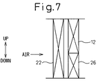
- FIG. 7 is an illustration of an arrangement of a heat exchanger according to the second embodiment of the present invention.
- FIG. 1 is a schematic illustration of a heat control system for a vehicle according to this embodiment.
- An engine 11 is a heat generator for generating a power for driving a vehicle
- a radiator 12 is a heat exchanger for cooling engine-cooling water by the heat-exchange between the engine-cooling water flowing out from the engine 11 and outer air.
- a thermostat 13 is a flow control valve for regulating a flow rate of the engine-cooling water fed to the radiator 12 by regulating a flow rate of the engine-cooling water passing through a bypass 12 a for returning the engine-cooling water flowing out from the engine 11 thereto while detouring the radiator 12 .
- a temperature controlling device is structured by the thermostat 13 and the radiator 12 , for maintaining a temperature of the engine 11 , that is, a temperature of the engine-cooling water within a predetermined range (for example, from 80 to 110° C.).
- a heater 14 is a heating means for heating air fed into a passenger compartment, while using waste heat of the engine 11 as a heat source, and an engine-cooling water circuit 10 is structured by the engine 11 , the radiator 12 , the thermostat 13 and the heater 14 .
- a pump 15 is used for circulating the engine-cooling water, which operates based on a power obtained from the engine 11 in this embodiment.
- a compressor 21 is used for sucking and compressing the refrigerant, which operates based on a power obtained from the engine 11 via a power-transmission device for intermittently transmitting the power, such as a magnetic clutch in this embodiment.
- a radiator 22 is a high-pressure side heat exchanger for cooling the high-temperature refrigerant discharged from the compressor 21 by the heat-exchange between the refrigerant and outer air.
- chlorofluorocarbon R134a
- the refrigerant is cooled and condensed in the radiator 22 to reduce the enthalpy thereof.
- a pressure reducer 23 is means for decompressing high-pressure refrigerant discharged from the radiator 22 , and in this embodiment, a so-called thermostatic expansion valve is adopted, for controlling an opening degree of a throttle so that an overheating degree of the refrigerant is maintained at a predetermined value.
- An evaporator 24 is a low-pressure side heat exchanger for exchanging heat between the decompressed low pressure refrigerant and air blown into the passenger compartment and evaporating liquid-phase refrigerant. By this evaporator 24 , air blown into the passenger compartment is cooled.
- the compressor 21 , the radiator 22 , the evaporator 22 and the pressure reducer 23 structure a vapor compression type refrigerator 20 , for transferring heat from the lower-temperature side to the higher-temperature side.
- a water-refrigerant heat exchanger 30 is a heat exchanger for exchanging heat between the refrigerant discharged from the compressor prior to being fed into the radiator and the engine-cooling water circulating the engine-cooling water circuit and, in this embodiment, an engine-cooling water entrance side of the water-refrigerant heat exchanger 30 is coupled to the bypass 12 a in the engine-cooling water circuit 10 and an engine-cooling water outlet side of the water-refrigerant heat exchanger 30 is coupled to an engine-cooling water inlet side of the water-refrigerant heat exchanger 30 .
- a directional selecting valve 31 is means for controlling a heat-exchanging rate between the engine-cooling water and the refrigerant in the water-refrigerant heat exchanger 30 by regulating an amount of the engine-cooling water fed to the water-refrigerant heat exchanger 30 , and the operation of the directional selecting valve 31 is controlled by an electronic controller (not shown) based on the temperature of the engine 11 ; that is, the temperature of the engine-cooling water discharged from the engine 11 .
- a bypass 25 is a passage for guiding the refrigerant, prior to being fed into the evaporator 24 , to the water-refrigerant heat exchanger 30 while bypassing the evaporator 24 and the compressor 21 , and a bypass valve 25 a is a valve for controlling the bypass 25 and is controlled by the electronic controller to be cooperative with the directional selecting valve 31 .
- This mode is carried out when the temperature of the engine 11 , that is, the temperature Tw of the engine-cooling water discharged from the engine 11 is lower than a first predetermined temperature (for example, 70° C.); i.e., when the temperature of the engine 11 is lower than the lower limit and the warming-up of the engine is necessary.
- a first predetermined temperature for example, 70° C.
- the compressor 21 is operated while circulating the cooling water through the water-refrigerant heat exchanger 30 under the condition that the bypass valve 25 a is closed.
- the refrigerant discharged from the compressor 21 circulates in the water-refrigerant heat exchanger 30 ⁇ the radiator 32 ⁇ the pressure reducer 23 ⁇ the evaporator 24 ⁇ the compressor 21 , heat in the hot refrigerant discharged from the compressor 21 is imparted to the engine-cooling water.
- the engine 11 is heated by the waste heat imparted from the vapor compression type refrigerator 20 in addition to heat it generates itself, it is possible to shorten the warming-up time in comparison with a case in which the warming-up is carried out solely with heat generated from itself.
- the temperature of the refrigerant discharged from the compressor 21 becomes high (for example, in a range from 60 to 70° C.) substantially at the same time as the compressor 21 has started. Thereby, it is possible to certainly heat the engine-cooling water with the refrigerant discharged from the compressor 21 even immediately after the engine 11 has started, that is, immediately after the compressor 21 has started.
- the heating mode is realized by the operation of the air-conditioner, of course, in a summer season necessitating the cooling, as well as in a winter season necessitating the dehumidified air-conditioning.
- This mode is executed when the temperature Tw of the engine-cooling water is higher than a second predetermined temperature (for example, 108° C.) which is higher than the upper limit of the first temperature range, that is, when the temperature of the engine 11 exceeds the upper limit of the above-mentioned temperature range and there is a risk in that it is difficult to cool the engine 11 solely by the radiator 12 .
- a second predetermined temperature for example, 108° C.
- the compressor 21 is operated under the condition that the bypass valve 25 a is opened to circulate the cooling water through the water-refrigerant heat exchanger 30 .
- the refrigerant discharged from the compressor 21 circulates in the water-refrigerant heat exchanger 30 ⁇ the radiator 22 ⁇ the pressure reducer 23 ⁇ the evaporator 24 ⁇ the compressor 21 , and the refrigerant branched through the bypass 25 is sucked into a refrigerant flow discharged from the compressor 21 to circulate through the water-refrigerant heat exchanger 30 ⁇ the radiator 22 ⁇ the water-refrigerant heat exchanger 30 .
- heat imparted to the refrigerant from the engine-cooling water in the water-refrigerant heat exchanger 30 is discharged to the outer air from the radiator 22 together with heat absorbed by the evaporator 24 .
- the cooling capacity of the radiator 12 is can be complemented by the radiator 22 , it is possible to be minimize the radiator 12 in size without lowering the cooling capacity.
- the radiator 22 is disposed upstream of the radiator 12 as seen in the flowing direction of the cooling air flow, the temperature difference between the refrigerant heated by the engine-cooling water and the outer air (cooling air) becomes larger to effectively cool the engine; i.e., the engine-cooling water.
- bypass 25 is coupled to the upstream of the pressure reducer 23 as seen in the refrigerant-flowing direction, it is possible to supply the liquid-phase refrigerant mainly by the bypass 25 to the water-refrigerant heat exchanger 30 .
- the waste heat of the engine 11 can be collected and discharged as an evaporation latent heat. Thereby, it is possible to collect the waste heat of the engine 11 and discharge the same therefrom.
- This mode is executed when the temperature Tw of the engine-cooling water is in a range from the first predetermined temperature Tw to the second predetermined temperature; that is, when the engine 11 is within the above-mentioned temperature range.
- the compressor 21 is operated without circulating the cooling water through the water-refrigerant heat exchanger 30 , while closing the bypass valve 25 a.
- the refrigerant discharged from the compressor 21 cools air fed into the passenger compartment, while circulating in series of the water-refrigerant heat exchanger 30 ⁇ the radiator 22 ⁇ the pressure reducer 23 ⁇ the evaporator 24 ⁇ the compressor 21 , and the engine-cooling water circuit 10 and the vapor compression type refrigerator 20 are thermally separated from each other.
- the temperature of the engine 11 that is, the temperature Tw of the engine-cooling water discharged from the engine 11 ; is read, and simultaneously therewith, it is determined whether or not a starting switch of the air-conditioner (the vapor compression type refrigerator 20 ) is ON; that is, whether or not the vapor compression type refrigerator 20 (the compressor 21 ) is in an operable state (S 1 , S 2 ). If the starting switch is ON, it is determined whether or not the temperature Tw is lower than the first predetermined temperature. If the temperature Tw is lower than the first predetermined temperature Tw, the heating mode (starting mode) is executed (S 4 , S 5 ).
- the normal mode is executed (S 6 to S 8 ) and, when the temperature Tw is lower than the second predetermined temperature, the heat dissipation mode (cooling-assist mode) is executed (S 9 , S 10 ).
- the bypass valve 25 a is closed to stop the circulation of the cooling water through the water-refrigerant heat exchanger 30 (S 11 , S 12 ) so that the engine-cooling water circuit 10 is thermally separated from the vapor compression type refrigerator 20 .
- the liquid-phase refrigerant is guided to the water-refrigerant heat exchanger 30 by coupling the bypass 25 to a position upstream from the pressure reducer 23 .
- the bypass 25 is eliminated and, instead, a cooler 26 is provided for cooling the refrigerant by the heat exchange between the refrigerant fed to the water-refrigerant heat exchanger 30 and outer air.
- the liquid-phase refrigerant is evaporated in the water-refrigerant heat exchanger 30 in the heat dissipation mode, it is possible to collect waste heat from the engine 11 as evaporation latent heat and to discharge the collected waste heat as condensation heat. Further, it is possible to effectively collect the waste heat from the engine 11 and discharge the collected waste heat.
- the radiator 12 can be small-sized and is arranged parallel to an air flow together with the cooler 26 as shown in FIG. 7 .
- cooler 26 is disposed beneath the radiator 12 in FIG. 7 , this embodiment should not be limited thereto, but the cooler 26 may be disposed above the radiator 12 .
- the refrigerant could be cooled by the cooler 26 in addition to the radiator 22 in the normal mode by arranging the cooler 26 downstream of the radiator 22 in the flowing direction of the cooling air or parallel to the flowing direction of the cooling air, it is possible to improve the heat-dissipation capacity of the vapor compression type refrigerator 20 and to reduce the power consumed in the compressor 21 .
- the directional selecting valve 31 is provided for positively controlling the three modes based on the temperature Tw.
- the present invention should not be limited thereto, but the directional selecting valve 31 may be eliminated so that the refrigerant and the engine-cooling water always circulate through the water-refrigerant heat exchanger 30 . Even in such a case, one of the three modes could be automatically selected in accordance with the temperature difference between the refrigerant and the engine-cooling water.
- the directional selecting valve 31 is provided in the cooling water circuit 10 .
- the present invention should not be limited thereto, but it may be provided, for example, in the circuit of the vapor compression type refrigerator 20 to select one of the three modes. In this regard, the operation is the same as in the above-mentioned embodiment.
- the present invention has been described based on the internal combustion engine which generates heat during the operation and must be maintained within a predetermined temperature range.
- the present invention should not be limited thereto, but may be applicable to a fuel cell, a battery, an electric motor or an electric circuit such as an inverter circuit, which generates heat during the operation.
- the engine-cooling water is adopted as a medium.
- the medium may be engine oil or automatic transmission fluid.
- the directional selecting valve 31 is electrically controlled.
- the present invention should not be limited thereto, but the valve 31 may be mechanically operated by using, for example, the volumetric change of wax material or others.
- the vapor compression type refrigerator 20 may be operated while using carbon dioxide as a refrigerant and maintaining the discharging pressure of the compressor 21 at the critical pressure of the refrigerant or higher.
- the expansion valve is used as the pressure-reducing means.
- the pressure may be reduced by a fixed throttle such as a capillary tube or that esentropically reducing the pressure of the refrigerant in a nozzle or an expander.
- the heating mode and the heat dissipation mode are carried out in the above-mentioned embodiments when the starting switch of the air conditioner is ON.
- the present invention should not be limited thereto, but the heating mode and the heat dissipation mode may be carried out without relying on a state of the starting switch of the air conditioner but may be carried out simultaneously with the start of the engine 11 based on the water temperature Tw.
Landscapes
- Engineering & Computer Science (AREA)
- Mechanical Engineering (AREA)
- Power Engineering (AREA)
- Transportation (AREA)
- Sustainable Energy (AREA)
- Life Sciences & Earth Sciences (AREA)
- Sustainable Development (AREA)
- Physics & Mathematics (AREA)
- Thermal Sciences (AREA)
- Chemical & Material Sciences (AREA)
- Combustion & Propulsion (AREA)
- General Engineering & Computer Science (AREA)
- Air-Conditioning For Vehicles (AREA)
Abstract
Description
Claims (6)
Applications Claiming Priority (2)
| Application Number | Priority Date | Filing Date | Title |
|---|---|---|---|
| JP2003-062897 | 2003-03-10 | ||
| JP2003062897A JP2004268752A (en) | 2003-03-10 | 2003-03-10 | Thermal management system |
Publications (2)
| Publication Number | Publication Date |
|---|---|
| US20040194949A1 US20040194949A1 (en) | 2004-10-07 |
| US7048044B2 true US7048044B2 (en) | 2006-05-23 |
Family
ID=33094811
Family Applications (1)
| Application Number | Title | Priority Date | Filing Date |
|---|---|---|---|
| US10/797,691 Expired - Fee Related US7048044B2 (en) | 2003-03-10 | 2004-03-09 | Heat control system |
Country Status (3)
| Country | Link |
|---|---|
| US (1) | US7048044B2 (en) |
| JP (1) | JP2004268752A (en) |
| DE (1) | DE102004011167A1 (en) |
Cited By (32)
| Publication number | Priority date | Publication date | Assignee | Title |
|---|---|---|---|---|
| US20050178523A1 (en) * | 2004-02-18 | 2005-08-18 | Satoshi Itoh | Automotive air conditioning system |
| US20050244691A1 (en) * | 2004-04-21 | 2005-11-03 | Conception Et Developpement Michelin S.A. | Electrical power train for a vehicle, comprising an electrical dissipation element cooled by cooling liquid |
| US20050241865A1 (en) * | 2004-04-21 | 2005-11-03 | Conception Et Developpement Michelin S.A. | Electrical power train for a fuel cell vehicle, comprising an electrical dissipation element |
| US20060144067A1 (en) * | 2004-12-13 | 2006-07-06 | Lg Electronics Inc. | Cooling/heating apparatus using cogeneration system |
| US20060242977A1 (en) * | 2005-04-28 | 2006-11-02 | Lg Electronics Inc. | Cogeneration system |
| US20060260336A1 (en) * | 2005-05-20 | 2006-11-23 | Heard Martin P | Manifold-superheated air conditioning system |
| US20080127913A1 (en) * | 2004-12-24 | 2008-06-05 | Renault Trucks | Engine Cooling System |
| US20080196877A1 (en) * | 2007-02-20 | 2008-08-21 | Bergstrom, Inc. | Combined Heating & Air Conditioning System for Buses Utilizing an Electrified Compressor Having a Modular High-Pressure Unit |
| US20080251235A1 (en) * | 2007-04-11 | 2008-10-16 | Telsa Motors, Inc. | Electric vehicle thermal management system |
| US20080302317A1 (en) * | 2007-06-07 | 2008-12-11 | Brown Myron L | Automatic by-pass safety cooling system for fire pump engines |
| US20090179509A1 (en) * | 2005-07-13 | 2009-07-16 | Oliver Gerundt | Method for influencing the temparture of an electromechanical component and device for carring out the method |
| US20090261176A1 (en) * | 2008-04-21 | 2009-10-22 | Gm Global Technology Operations, Inc. | Heater Coolant Flow Control for HVAC Module |
| US20100043465A1 (en) * | 2008-08-25 | 2010-02-25 | Lg Electronics Inc. | Heat pump system and method of controlling the same |
| WO2012082050A1 (en) * | 2010-12-14 | 2012-06-21 | Scania Cv Ab | Radiator arrangement in a vehicle powered by a combustion engine |
| US8336319B2 (en) | 2010-06-04 | 2012-12-25 | Tesla Motors, Inc. | Thermal management system with dual mode coolant loops |
| US20130118707A1 (en) * | 2010-08-12 | 2013-05-16 | Zoltan Kardos | Arrangement for maintaining a desired operating temperature of a battery in a vehicle |
| US8773058B2 (en) | 2010-07-08 | 2014-07-08 | Tesla Motors, Inc. | Rotor temperature estimation and motor control torque limiting for vector-controlled AC induction motors |
| US20140298853A1 (en) * | 2011-12-19 | 2014-10-09 | Behr Gmbh & Co. Kg | Heat exchanger |
| US20140311704A1 (en) * | 2011-11-21 | 2014-10-23 | Hitachi Automotive Systems, Ltd. | Cooling Apparatus |
| US20140353392A1 (en) * | 2013-06-03 | 2014-12-04 | Hyundai Motor Company | Heating system for electric vehicle |
| US20150115048A1 (en) * | 2013-10-29 | 2015-04-30 | Denso International America, Inc. | Thermostatic controlled heat pump water circuit |
| US20150174986A1 (en) * | 2012-09-10 | 2015-06-25 | Bayerische Motoren Werke Aktiengesellschaft | Method from the thermal conditioning of an internal combustion engine and/or of a passenger compartment of a vehicle, and vehicle |
| WO2016130149A1 (en) * | 2015-02-13 | 2016-08-18 | Imo Industries, Inc. | Intelligent sea water cooling system and method |
| US10427491B2 (en) | 2011-09-28 | 2019-10-01 | Tesla, Inc. | Thermal management system with heat exchanger blending valve |
| US10522845B2 (en) | 2011-09-28 | 2019-12-31 | Tesla, Inc. | Battery centric thermal management system utilizing a heat exchanger blending valve |
| US10794231B2 (en) * | 2016-05-20 | 2020-10-06 | Safran | Reversible system for dissipating thermal power generated in a gas-turbine engine |
| US11221165B2 (en) * | 2019-09-17 | 2022-01-11 | Laird Thermal Systems, Inc. | Temperature regulating refrigeration systems for varying loads |
| US11407280B1 (en) | 2022-02-10 | 2022-08-09 | Rancho Del I.P. | Ultra-low-cost coolant heating apparatus for electric vehicle applications |
| US20220305877A1 (en) * | 2020-01-15 | 2022-09-29 | Ford Global Technologies, Llc | Thermal management for electrified vehicle |
| US11766920B2 (en) | 2022-02-10 | 2023-09-26 | Rancho Del I.P. | Selective efficiency traction inverters and chargers as heat sources for thermal conditioning of electric vehicles |
| US20240162530A1 (en) * | 2022-11-10 | 2024-05-16 | Hyundai Motor Company | Coolant Management System for Mobility Vehicle |
| US20250042223A1 (en) * | 2023-08-03 | 2025-02-06 | Hitachi Rail Sts S.P.A. | Electric or hybrid traction vehicle equipped with an air conditioning system, with heat recovery from cooling of electrical and/or electronic components |
Families Citing this family (27)
| Publication number | Priority date | Publication date | Assignee | Title |
|---|---|---|---|---|
| FR2904791B1 (en) * | 2006-08-11 | 2011-04-01 | Peugeot Citroen Automobiles Sa | METHOD FOR REFRIGERATING A MOTOR VEHICLE HABITACLE, REFRIGERATION ASSEMBLY AND AUTOMOTIVE VEHICLE |
| US8205427B2 (en) * | 2006-11-09 | 2012-06-26 | United Technologies Corporation | Interdependent lubrication systems in a turbine engine |
| JP2008143266A (en) * | 2006-12-07 | 2008-06-26 | Calsonic Kansei Corp | Heat exchanger |
| DE102008030969A1 (en) * | 2008-06-30 | 2009-12-31 | Agco Gmbh | Flow Control |
| SE533436C2 (en) * | 2008-11-26 | 2010-09-28 | Scania Cv Ab | Method and system for overcooling the coolant in a vehicle's cooling system. |
| US20100206543A1 (en) * | 2009-02-13 | 2010-08-19 | Tylisz Brian M | Two-stage heat exchanger with interstage bypass |
| US8905321B2 (en) * | 2009-04-02 | 2014-12-09 | Manitowoc Crane Companies, Llc | System for supplying heat to construction equipment cab |
| DE102009056616B4 (en) * | 2009-12-02 | 2018-10-25 | Audi Ag | Method for distributing heat in a coolant circuit of a vehicle |
| JP5729910B2 (en) * | 2010-03-05 | 2015-06-03 | 三菱重工業株式会社 | Hot water heat pump and control method thereof |
| JP5626194B2 (en) * | 2010-12-21 | 2014-11-19 | 株式会社デンソー | Heat exchange system |
| JP5755490B2 (en) * | 2011-04-18 | 2015-07-29 | トヨタ自動車株式会社 | Cooling system |
| FR2979288B1 (en) * | 2011-08-25 | 2013-08-23 | Valeo Systemes Thermiques | DEVICE FOR MONITORING A FLOW OF REFRIGERANT FLUID AND CIRCUIT INCORPORATING SUCH A DEVICE |
| JP5861714B2 (en) * | 2011-10-12 | 2016-02-16 | 日産自動車株式会社 | Electric vehicle |
| DE102013206171A1 (en) * | 2013-04-09 | 2014-10-09 | Bayerische Motoren Werke Aktiengesellschaft | Method for operating a CO2 refrigerant circuit and CO2 refrigerant circuit |
| US9863671B2 (en) * | 2014-07-29 | 2018-01-09 | Ford Global Technologies, Llc | Heat pump assisted engine cooling for electrified vehicles |
| US10290911B2 (en) * | 2015-05-18 | 2019-05-14 | Toyota Motor Engineering & Manufacturing North America, Inc. | Cooling loops and vehicles incorporating the same |
| JP6491969B2 (en) * | 2015-06-29 | 2019-03-27 | カルソニックカンセイ株式会社 | Air conditioner for vehicles |
| SE540931C2 (en) * | 2015-10-27 | 2018-12-27 | Scania Cv Ab | A cooling system for a WHR system |
| CN106014585A (en) * | 2016-05-17 | 2016-10-12 | 李明科 | Cooling device suitable for internal combustion engine |
| CN106837520A (en) * | 2017-01-19 | 2017-06-13 | 成都叮当自动化设备有限公司 | A kind of cryogenic engine for preheating |
| FR3070557A1 (en) * | 2017-08-29 | 2019-03-01 | Valeo Systemes Thermiques | ELECTRICAL CONNECTION DEVICE FOR A MOTOR VEHICLE COOLED BY A REFRIGERANT FLUID CIRCUIT |
| CN107489509A (en) * | 2017-10-19 | 2017-12-19 | 劳福厚 | A kind of Water cooling device for motorcycle engine |
| KR20190120936A (en) * | 2018-04-17 | 2019-10-25 | 한온시스템 주식회사 | Heat management system of vehicle |
| JP7281387B2 (en) * | 2019-11-08 | 2023-05-25 | Ckd株式会社 | Temperature control system and integrated temperature control system |
| CN111930157A (en) * | 2020-09-17 | 2020-11-13 | 江苏苏美达机电科技有限公司 | Constant temperature control system and method for interior of box type generator set |
| EP4339002A1 (en) * | 2022-09-14 | 2024-03-20 | Volvo Truck Corporation | An electric energy dissipating system for a vehicle |
| CN120120755B (en) * | 2025-05-15 | 2025-07-11 | 福建三明金氟化工科技有限公司 | An electronic grade fluorine gas refrigeration device and impurity absorption system |
Citations (6)
| Publication number | Priority date | Publication date | Assignee | Title |
|---|---|---|---|---|
| JPH11286211A (en) | 1998-04-02 | 1999-10-19 | Matsushita Electric Ind Co Ltd | Vehicle air conditioner |
| US6047770A (en) * | 1997-07-24 | 2000-04-11 | Denso Corporation | Air conditioning apparatus for vehicle |
| JP2002516595A (en) | 1998-04-25 | 2002-06-04 | ヴィステオン グローバル テクノロジーズ インコーポレーテッド | Vehicle air conditioner and method of using the same |
| US20030010488A1 (en) * | 2001-07-12 | 2003-01-16 | Toshiharu Watanabe | Cooling cycle |
| US6543531B1 (en) * | 1998-03-27 | 2003-04-08 | Daimlerchrysler Ag | Device and method for heating and cooling a compartment of a motor vehicle |
| US6913067B2 (en) * | 2002-02-20 | 2005-07-05 | Zexel Valeo Compressor Europe Gmbh | Vehicle conditioning system |
-
2003
- 2003-03-10 JP JP2003062897A patent/JP2004268752A/en active Pending
-
2004
- 2004-03-08 DE DE102004011167A patent/DE102004011167A1/en not_active Withdrawn
- 2004-03-09 US US10/797,691 patent/US7048044B2/en not_active Expired - Fee Related
Patent Citations (6)
| Publication number | Priority date | Publication date | Assignee | Title |
|---|---|---|---|---|
| US6047770A (en) * | 1997-07-24 | 2000-04-11 | Denso Corporation | Air conditioning apparatus for vehicle |
| US6543531B1 (en) * | 1998-03-27 | 2003-04-08 | Daimlerchrysler Ag | Device and method for heating and cooling a compartment of a motor vehicle |
| JPH11286211A (en) | 1998-04-02 | 1999-10-19 | Matsushita Electric Ind Co Ltd | Vehicle air conditioner |
| JP2002516595A (en) | 1998-04-25 | 2002-06-04 | ヴィステオン グローバル テクノロジーズ インコーポレーテッド | Vehicle air conditioner and method of using the same |
| US20030010488A1 (en) * | 2001-07-12 | 2003-01-16 | Toshiharu Watanabe | Cooling cycle |
| US6913067B2 (en) * | 2002-02-20 | 2005-07-05 | Zexel Valeo Compressor Europe Gmbh | Vehicle conditioning system |
Cited By (59)
| Publication number | Priority date | Publication date | Assignee | Title |
|---|---|---|---|---|
| US20050178523A1 (en) * | 2004-02-18 | 2005-08-18 | Satoshi Itoh | Automotive air conditioning system |
| US7520320B2 (en) * | 2004-02-18 | 2009-04-21 | Denso Corporation | Automotive air conditioning system |
| US7404461B2 (en) | 2004-04-21 | 2008-07-29 | Conception Et Developpement Michelin, S.A. | Electrical power train for a fuel cell vehicle, comprising an electrical dissipation element |
| US20050244691A1 (en) * | 2004-04-21 | 2005-11-03 | Conception Et Developpement Michelin S.A. | Electrical power train for a vehicle, comprising an electrical dissipation element cooled by cooling liquid |
| US20050241865A1 (en) * | 2004-04-21 | 2005-11-03 | Conception Et Developpement Michelin S.A. | Electrical power train for a fuel cell vehicle, comprising an electrical dissipation element |
| US7383903B2 (en) * | 2004-04-21 | 2008-06-10 | Conception Et Developpement Michelin S.A. | Electrical power train for a vehicle, comprising an electrical dissipation element cooled by cooling liquid |
| US20060144067A1 (en) * | 2004-12-13 | 2006-07-06 | Lg Electronics Inc. | Cooling/heating apparatus using cogeneration system |
| US7481071B2 (en) * | 2004-12-13 | 2009-01-27 | Lg Electronics Inc. | Cooling/heating apparatus using cogeneration system |
| US20080127913A1 (en) * | 2004-12-24 | 2008-06-05 | Renault Trucks | Engine Cooling System |
| US7673593B2 (en) * | 2004-12-24 | 2010-03-09 | Renault Trucks | Engine cooling system |
| US20060242977A1 (en) * | 2005-04-28 | 2006-11-02 | Lg Electronics Inc. | Cogeneration system |
| US7412843B2 (en) * | 2005-05-20 | 2008-08-19 | Martin Perry Heard | Manifold-superheated air conditioning system |
| US20060260336A1 (en) * | 2005-05-20 | 2006-11-23 | Heard Martin P | Manifold-superheated air conditioning system |
| US20090179509A1 (en) * | 2005-07-13 | 2009-07-16 | Oliver Gerundt | Method for influencing the temparture of an electromechanical component and device for carring out the method |
| US8622120B2 (en) * | 2005-07-13 | 2014-01-07 | Robert Bosch Gmbh | Method for influencing the temperature of an electromechanical component and device for carrying out the method |
| US8517087B2 (en) * | 2007-02-20 | 2013-08-27 | Bergstrom, Inc. | Combined heating and air conditioning system for vehicles |
| US20080196877A1 (en) * | 2007-02-20 | 2008-08-21 | Bergstrom, Inc. | Combined Heating & Air Conditioning System for Buses Utilizing an Electrified Compressor Having a Modular High-Pressure Unit |
| US20080251235A1 (en) * | 2007-04-11 | 2008-10-16 | Telsa Motors, Inc. | Electric vehicle thermal management system |
| US7789176B2 (en) * | 2007-04-11 | 2010-09-07 | Tesla Motors, Inc. | Electric vehicle thermal management system |
| US20100025006A1 (en) * | 2007-04-11 | 2010-02-04 | Tesla Motors, Inc. | Electric vehicle thermal management system |
| US7841431B2 (en) | 2007-04-11 | 2010-11-30 | Tesla Motors, Inc. | Electric vehicle thermal management system |
| US20080302317A1 (en) * | 2007-06-07 | 2008-12-11 | Brown Myron L | Automatic by-pass safety cooling system for fire pump engines |
| US7743740B2 (en) * | 2007-06-07 | 2010-06-29 | Brown Myron L | Automatic by-pass safety cooling system for fire pump engines |
| US8740103B2 (en) * | 2008-04-21 | 2014-06-03 | GM Global Technology Operations LLC | Heater coolant flow control for HVAC module |
| US20090261176A1 (en) * | 2008-04-21 | 2009-10-22 | Gm Global Technology Operations, Inc. | Heater Coolant Flow Control for HVAC Module |
| US20100043465A1 (en) * | 2008-08-25 | 2010-02-25 | Lg Electronics Inc. | Heat pump system and method of controlling the same |
| US8448696B2 (en) | 2010-06-04 | 2013-05-28 | Tesla Motors, Inc. | Coolant de-aeration reservoir |
| US8402776B2 (en) | 2010-06-04 | 2013-03-26 | Tesla Motors, Inc. | Thermal management system with dual mode coolant loops |
| US8336319B2 (en) | 2010-06-04 | 2012-12-25 | Tesla Motors, Inc. | Thermal management system with dual mode coolant loops |
| US8773058B2 (en) | 2010-07-08 | 2014-07-08 | Tesla Motors, Inc. | Rotor temperature estimation and motor control torque limiting for vector-controlled AC induction motors |
| US9758009B2 (en) * | 2010-08-12 | 2017-09-12 | Scania Cv Ab | Arrangement for maintaining a desired operating temperature of a battery in a vehicle |
| US20130118707A1 (en) * | 2010-08-12 | 2013-05-16 | Zoltan Kardos | Arrangement for maintaining a desired operating temperature of a battery in a vehicle |
| WO2012082050A1 (en) * | 2010-12-14 | 2012-06-21 | Scania Cv Ab | Radiator arrangement in a vehicle powered by a combustion engine |
| US20130255296A1 (en) * | 2010-12-14 | 2013-10-03 | Zoltan Kardos | Radiator arrangement in a vehicle powered by a combustion engine |
| EP2651675A4 (en) * | 2010-12-14 | 2018-03-28 | Scania CV AB | Radiator arrangement in a vehicle powered by a combustion engine |
| US10522845B2 (en) | 2011-09-28 | 2019-12-31 | Tesla, Inc. | Battery centric thermal management system utilizing a heat exchanger blending valve |
| US10427491B2 (en) | 2011-09-28 | 2019-10-01 | Tesla, Inc. | Thermal management system with heat exchanger blending valve |
| US20140311704A1 (en) * | 2011-11-21 | 2014-10-23 | Hitachi Automotive Systems, Ltd. | Cooling Apparatus |
| US20140298853A1 (en) * | 2011-12-19 | 2014-10-09 | Behr Gmbh & Co. Kg | Heat exchanger |
| US10240826B2 (en) * | 2011-12-19 | 2019-03-26 | Mahle International Gmbh | Heat exchanger |
| US11850915B2 (en) * | 2012-09-10 | 2023-12-26 | Bayerische Motoren Werke Aktiengesellschaft | Method for the thermal conditioning of an internal combustion engine and/or of a passenger compartment of a vehicle, and vehicle |
| US20150174986A1 (en) * | 2012-09-10 | 2015-06-25 | Bayerische Motoren Werke Aktiengesellschaft | Method from the thermal conditioning of an internal combustion engine and/or of a passenger compartment of a vehicle, and vehicle |
| US20180251003A1 (en) * | 2012-09-10 | 2018-09-06 | Bayerische Motoren Werke Aktiengesellschaft | Method from the Thermal Conditioning of an Internal Combustion Engine and/or of a Passenger Compartment of a Vehicle, and Vehicle |
| US20140353392A1 (en) * | 2013-06-03 | 2014-12-04 | Hyundai Motor Company | Heating system for electric vehicle |
| US20150115048A1 (en) * | 2013-10-29 | 2015-04-30 | Denso International America, Inc. | Thermostatic controlled heat pump water circuit |
| US9630474B2 (en) * | 2013-10-29 | 2017-04-25 | Denso International America, Inc. | Thermostatic controlled heat pump water circuit |
| WO2016130149A1 (en) * | 2015-02-13 | 2016-08-18 | Imo Industries, Inc. | Intelligent sea water cooling system and method |
| US10400658B2 (en) | 2015-02-13 | 2019-09-03 | Circor Pumps North America, Llc | Intelligent sea water cooling system and method |
| US10794231B2 (en) * | 2016-05-20 | 2020-10-06 | Safran | Reversible system for dissipating thermal power generated in a gas-turbine engine |
| US11619433B2 (en) | 2019-09-17 | 2023-04-04 | Laird Thermal Systems Inc. | Temperature regulating refrigeration systems for varying loads |
| US11221165B2 (en) * | 2019-09-17 | 2022-01-11 | Laird Thermal Systems, Inc. | Temperature regulating refrigeration systems for varying loads |
| US20220305877A1 (en) * | 2020-01-15 | 2022-09-29 | Ford Global Technologies, Llc | Thermal management for electrified vehicle |
| US11951799B2 (en) * | 2020-01-15 | 2024-04-09 | Ford Global Technologies, Llc | Thermal management for electrified vehicle |
| US11407280B1 (en) | 2022-02-10 | 2022-08-09 | Rancho Del I.P. | Ultra-low-cost coolant heating apparatus for electric vehicle applications |
| US11766920B2 (en) | 2022-02-10 | 2023-09-26 | Rancho Del I.P. | Selective efficiency traction inverters and chargers as heat sources for thermal conditioning of electric vehicles |
| US12179558B2 (en) | 2022-02-10 | 2024-12-31 | Rancho Del I.P. | Electric vehicle thermal management and safety apparatus |
| US20240162530A1 (en) * | 2022-11-10 | 2024-05-16 | Hyundai Motor Company | Coolant Management System for Mobility Vehicle |
| US20250042223A1 (en) * | 2023-08-03 | 2025-02-06 | Hitachi Rail Sts S.P.A. | Electric or hybrid traction vehicle equipped with an air conditioning system, with heat recovery from cooling of electrical and/or electronic components |
| US12466239B2 (en) * | 2023-08-03 | 2025-11-11 | Hitachi Rail Sts S.P.A. | Electric or hybrid traction vehicle equipped with an air conditioning system, with heat recovery from cooling of electrical and/or electronic components |
Also Published As
| Publication number | Publication date |
|---|---|
| US20040194949A1 (en) | 2004-10-07 |
| JP2004268752A (en) | 2004-09-30 |
| DE102004011167A1 (en) | 2004-12-16 |
Similar Documents
| Publication | Publication Date | Title |
|---|---|---|
| US7048044B2 (en) | Heat control system | |
| US12240290B2 (en) | Heat pump system for vehicle | |
| US7841431B2 (en) | Electric vehicle thermal management system | |
| US7182129B2 (en) | Device for heating and/or air-conditioning the passenger compartment of a motor vehicle | |
| EP3621839B1 (en) | A cooling arrangement for cooling of an electric machine and at least one further component of an electric power unit and a vehicle comprising such a cooling arrangement | |
| US10071614B2 (en) | Vehicle air conditioner | |
| CN112074425A (en) | Vehicle thermal management system | |
| JP2002352867A (en) | Battery temperature control device for electric vehicles | |
| US12285996B2 (en) | Method for controlling vehicle thermal management system | |
| US20090013705A1 (en) | Refrigeration apparatus with exhaust heat recovery device | |
| CN113370741A (en) | Vehicle-mounted temperature adjusting system | |
| JP2002354608A (en) | Electric vehicle battery cooling system | |
| JP2011068348A (en) | Vehicle inside temperature control method of electric motor vehicle and air-conditioning system | |
| JP2009190579A (en) | Air conditioning system | |
| US10611212B2 (en) | Air conditioner for vehicle | |
| CN113370739A (en) | Vehicle-mounted temperature adjusting system | |
| CN108859654A (en) | Automobile heat pump air-conditioning system and automobile heat pump air conditioner assembly | |
| CN118238583A (en) | Electric vehicle thermal management system and method | |
| CN112302778A (en) | Thermal management device and management method for a hybrid electric vehicle | |
| JP2017128223A (en) | Vehicle coolant heating apparatus and vehicle coolant heating program | |
| US11085354B2 (en) | Control method for integrated thermal management system of vehicle | |
| CN120019528A (en) | Temperature control system and temperature control method for vehicle | |
| JP4029745B2 (en) | Thermal management system | |
| US8806881B2 (en) | System for controlling the thermal energy of a motor vehicle engine by adjusting the fluid actuators of said system | |
| KR20230103867A (en) | Heat management system of vehicle |
Legal Events
| Date | Code | Title | Description |
|---|---|---|---|
| AS | Assignment |
Owner name: DENSO CORPORATION, JAPAN Free format text: ASSIGNMENT OF ASSIGNORS INTEREST;ASSIGNORS:BAN, KOICHI;YAMANAKA, YASUSHI;SUZUKI, TAKAHISA;AND OTHERS;REEL/FRAME:015079/0884 Effective date: 20040225 |
|
| FPAY | Fee payment |
Year of fee payment: 4 |
|
| FEPP | Fee payment procedure |
Free format text: PAYOR NUMBER ASSIGNED (ORIGINAL EVENT CODE: ASPN); ENTITY STATUS OF PATENT OWNER: LARGE ENTITY |
|
| FPAY | Fee payment |
Year of fee payment: 8 |
|
| FEPP | Fee payment procedure |
Free format text: MAINTENANCE FEE REMINDER MAILED (ORIGINAL EVENT CODE: REM.) |
|
| LAPS | Lapse for failure to pay maintenance fees |
Free format text: PATENT EXPIRED FOR FAILURE TO PAY MAINTENANCE FEES (ORIGINAL EVENT CODE: EXP.) |
|
| STCH | Information on status: patent discontinuation |
Free format text: PATENT EXPIRED DUE TO NONPAYMENT OF MAINTENANCE FEES UNDER 37 CFR 1.362 |
|
| FP | Lapsed due to failure to pay maintenance fee |
Effective date: 20180523 |