US7039853B2 - Multi-mode Reed-Solomon decoder based upon the PGZ algorithm and associated method - Google Patents
Multi-mode Reed-Solomon decoder based upon the PGZ algorithm and associated method Download PDFInfo
- Publication number
- US7039853B2 US7039853B2 US10/302,825 US30282502A US7039853B2 US 7039853 B2 US7039853 B2 US 7039853B2 US 30282502 A US30282502 A US 30282502A US 7039853 B2 US7039853 B2 US 7039853B2
- Authority
- US
- United States
- Prior art keywords
- error
- syndrome
- mode
- polynomial
- reed
- Prior art date
- Legal status (The legal status is an assumption and is not a legal conclusion. Google has not performed a legal analysis and makes no representation as to the accuracy of the status listed.)
- Expired - Lifetime, expires
Links
- 238000004422 calculation algorithm Methods 0.000 title claims abstract description 45
- 238000000034 method Methods 0.000 title claims description 23
- 208000011580 syndromic disease Diseases 0.000 claims description 42
- 238000012937 correction Methods 0.000 claims description 24
- 239000011159 matrix material Substances 0.000 claims description 12
- 238000004364 calculation method Methods 0.000 claims description 10
- 230000001419 dependent effect Effects 0.000 claims description 2
- 238000004891 communication Methods 0.000 abstract description 2
- 238000005457 optimization Methods 0.000 abstract 1
- 238000010586 diagram Methods 0.000 description 4
- 238000013461 design Methods 0.000 description 3
- 230000014509 gene expression Effects 0.000 description 2
- 238000004519 manufacturing process Methods 0.000 description 2
- 238000012986 modification Methods 0.000 description 2
- 230000004048 modification Effects 0.000 description 2
- 230000005540 biological transmission Effects 0.000 description 1
- 238000009795 derivation Methods 0.000 description 1
- 230000000694 effects Effects 0.000 description 1
- 239000000284 extract Substances 0.000 description 1
- 230000004044 response Effects 0.000 description 1
Images


Classifications
-
- H—ELECTRICITY
- H03—ELECTRONIC CIRCUITRY
- H03M—CODING; DECODING; CODE CONVERSION IN GENERAL
- H03M13/00—Coding, decoding or code conversion, for error detection or error correction; Coding theory basic assumptions; Coding bounds; Error probability evaluation methods; Channel models; Simulation or testing of codes
- H03M13/65—Purpose and implementation aspects
- H03M13/6502—Reduction of hardware complexity or efficient processing
-
- H—ELECTRICITY
- H03—ELECTRONIC CIRCUITRY
- H03M—CODING; DECODING; CODE CONVERSION IN GENERAL
- H03M13/00—Coding, decoding or code conversion, for error detection or error correction; Coding theory basic assumptions; Coding bounds; Error probability evaluation methods; Channel models; Simulation or testing of codes
- H03M13/03—Error detection or forward error correction by redundancy in data representation, i.e. code words containing more digits than the source words
- H03M13/05—Error detection or forward error correction by redundancy in data representation, i.e. code words containing more digits than the source words using block codes, i.e. a predetermined number of check bits joined to a predetermined number of information bits
- H03M13/13—Linear codes
- H03M13/15—Cyclic codes, i.e. cyclic shifts of codewords produce other codewords, e.g. codes defined by a generator polynomial, Bose-Chaudhuri-Hocquenghem [BCH] codes
- H03M13/151—Cyclic codes, i.e. cyclic shifts of codewords produce other codewords, e.g. codes defined by a generator polynomial, Bose-Chaudhuri-Hocquenghem [BCH] codes using error location or error correction polynomials
- H03M13/1525—Determination and particular use of error location polynomials
-
- H—ELECTRICITY
- H03—ELECTRONIC CIRCUITRY
- H03M—CODING; DECODING; CODE CONVERSION IN GENERAL
- H03M13/00—Coding, decoding or code conversion, for error detection or error correction; Coding theory basic assumptions; Coding bounds; Error probability evaluation methods; Channel models; Simulation or testing of codes
- H03M13/03—Error detection or forward error correction by redundancy in data representation, i.e. code words containing more digits than the source words
- H03M13/05—Error detection or forward error correction by redundancy in data representation, i.e. code words containing more digits than the source words using block codes, i.e. a predetermined number of check bits joined to a predetermined number of information bits
- H03M13/13—Linear codes
- H03M13/15—Cyclic codes, i.e. cyclic shifts of codewords produce other codewords, e.g. codes defined by a generator polynomial, Bose-Chaudhuri-Hocquenghem [BCH] codes
- H03M13/151—Cyclic codes, i.e. cyclic shifts of codewords produce other codewords, e.g. codes defined by a generator polynomial, Bose-Chaudhuri-Hocquenghem [BCH] codes using error location or error correction polynomials
- H03M13/158—Finite field arithmetic processing
-
- H—ELECTRICITY
- H03—ELECTRONIC CIRCUITRY
- H03M—CODING; DECODING; CODE CONVERSION IN GENERAL
- H03M13/00—Coding, decoding or code conversion, for error detection or error correction; Coding theory basic assumptions; Coding bounds; Error probability evaluation methods; Channel models; Simulation or testing of codes
- H03M13/03—Error detection or forward error correction by redundancy in data representation, i.e. code words containing more digits than the source words
- H03M13/05—Error detection or forward error correction by redundancy in data representation, i.e. code words containing more digits than the source words using block codes, i.e. a predetermined number of check bits joined to a predetermined number of information bits
- H03M13/13—Linear codes
- H03M13/15—Cyclic codes, i.e. cyclic shifts of codewords produce other codewords, e.g. codes defined by a generator polynomial, Bose-Chaudhuri-Hocquenghem [BCH] codes
- H03M13/151—Cyclic codes, i.e. cyclic shifts of codewords produce other codewords, e.g. codes defined by a generator polynomial, Bose-Chaudhuri-Hocquenghem [BCH] codes using error location or error correction polynomials
- H03M13/1585—Determination of error values
Definitions
- the invention relates to a Reed-Solomon decoder. More particularly, the invention relates to a multi-mode Reed-Solomon decoder based upon the Peterson-Gorenstein-Zierler (PGZ) algorithm.
- PGZ Peterson-Gorenstein-Zierler
- the Reed-Solomon (RS) codes have a strong error-correcting ability for burst transmission errors. Therefore, the RS codes have been widely used for error correction in digital communication and storage systems such as the xDSL, the cable modem, between a processor and a memory, the CD and the DVD.
- the Peterson-Gorenstein-Zierler (PGZ) algorithm provides the simplest method for implementing a RS decoder for t ⁇ 3. This is a low-cost solution for such systems as the error control code (ECC) between a processor and a memory that requires smaller error-correcting ability.
- ECC error control code
- the invention provides a VLSI architecture to build a multi-mode Reed-Solomon decoder that can perform all sorts of corrections using the PGZ algorithm.
- An objective of the invention is to provide a multi-mode Reed-Solomon decoder that can make corrections in response to error situations based upon the PGZ algorithm.
- Another objective of the invention is to provide a multi-mode PGZ decoder circuit in a VLSI architecture that has a lower cost and uses fewer area resources to solve various error correction problems.
- the implementation requires a larger area and results in lowering the efficiency of hardware resources.
- the implementation of the algorithm includes the operation of the FFI. This inevitably increases the complexity of the circuit calculation and deteriorates the calculation speed. Therefore, the invention ultilizes the derivation of the algorithm to obtain the disclosed Reed-Solomon decoder without requiring FFI. The occupied area resource is thus reduced, whereas the operation efficiency is enhanced.
- a Reed-Solomon decoding method comprises the steps of: computing the syndromes of received data; solving the key equation; and evaluating error locations and error value, wherein the step for solving the key equation is based upon a simplified PGZ algorithm and a solution that does not need FFI in operations. This greatly reduces the complexity of the computation and the area resources occupied by the hardware.
- the Reed-Solomon decoder comprising: a syndrome calculator to compute the syndromes of received data; a key equation solver to receive a syndrome equation from the syndrome calculator; and an error location and error value evaluator to receive the syndrome equation and obtain the error locations and error value.
- the key equation solver uses a simplified PGZ decoder as the basis thereof.
- the PGZ decoding architecture comprises FFA and FFM without requiring FFI.
- FIG. 1 shows a block diagram of the Reed-Solomon decoding procedure
- FIG. 2 is a circuit block diagram for the conventional PGZ decoding architecture that uses the duplicate hardware circuits to achieve error corrections;
- FIG. 3 is a circuit block diagram of the multi-mode PGZ decoder with a single hardware to perform different error corrections according to one embodiment of the present invention
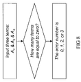
- FIG. 8 shows a flowchart of the multi-mode decoding method according to one embodiment of the present invention.
- FIG. 9 shows an RTL hardware architecture of the multi-mode PGZ decoding architecture according to one embodiment of the present invention.
- a Reed-Solomon decoding procedure comprises computing the syndromes of a reception polynomial r(x) to obtain a syndrome polynomial S(x); solving the key equation to obtain an error location polynomial ⁇ (x) and an error value polynomial ⁇ (x) in accordance with the syndrome polynomial S(x); evaluating error locations and error value in accordance with the error location polynomial ⁇ (x) and the error value polynomial ⁇ (x); and correcting the errors in the received data in accordance with the error locations and the error value to obtain a transmitted codeword polynomial c(x).
- the syndrome values S i obtained from ⁇ i in the reception polynomial r(x) can be expressed as:
- the PGZ algorithm for solving the key equation includes the step of solving the Newton Identity:
- the syndrome values S i are used to solve for ⁇ in Eq. (4).
- Eq. (8) is obtained from Eq. (4).
- Eq. (10) is obtained from Eq. (4)
- FIG. 5 the RTL hardware architecture using the PGZ algorithm to solve Eqs. (10) and (11) is shown in FIG. 5 , which includes:
- Eq. (12) is obtained from Eq. (4):
- the RTL hardware architecture using the PGZ algorithm to solve Eqs. (12) and (13) includes:
- the Reed-Solomon decoder based upon the conventional PGZ algorithm requires a larger area in an IC and has a low hardware resource utilization. Furthermore, the implementation of the algorithm requires the FFI operations, which complicates the circuit design and deteriorates the calculation speed.
- the invention simplifies the algorithm so that the disclosed Reed-Solomon is less complicated in calculations. Furthermore, it requires no FFI operations when solving key equations. This can effectively reduce die size while increasing the calculation efficiency.
- the denominators of ⁇ 0 , ⁇ 1 , ⁇ 2 two terms of S 3 S 4 S 5 are cancelled in FFA.
- the numerator of ⁇ 0 has two terms of S 2 S 3 S 4 that can be cancelled in FFA.
- the product terms S 2 S 2 S 5 , S 2 S 3 S 5 , S 2 S 4 S 5 , S 2 S 5 S 5 of ⁇ 0 , ⁇ 1 , ⁇ 2 in Eq. (12) have a common term S 2 S 5 .
- the disclosed solving procedure first computes the value of S 2 S 5 to reduce the calculation complexity.
- Other common terms S 2 S 6 , S 4 S 4 , S 3 S 3 , S 1 S 5 , and S 1 S 6 can be similarly computed, too.
- the solving process of the PGZ algorithm involves FFI operation. This does not only lower the computing speed of the hardware but also occupy die size area. Thus, the invention further simplifies the PGZ algorithm so as to reduce FFI operation 106 .
- the conventional PGZ architecture utilizes the redundant hardware circuits to achieve different error-correcting abilities (t ⁇ 3), as shown in FIG. 2 .
- the invention extracts important information from Eqs. (28) and (29). Such information can be used to find out the number of errors. Explicitly,
- Multi-mode decoding procedure based on the simplified PGZ algorithm is shown in FIG. 8 .
- a controller 107 is capable of obtaining the number of errors as shown in FIG. 8 .
- the multi-mode PGZ decoder 100 accomplishes the goal of using one circuit to solve different errors (t ⁇ 3).
- FIG. 9 shows an RTL hardware embodiment of the multi-mode PGZ decoder 100 according to the present invention, which includes:
- the Reed-Solomon decoding procedure comprises the steps of: computing the syndrome of received data; solving a key equation; and evaluating error locations and error value, wherein the step for solving the key equation is based upon the simplified PGZ algorithm.
- a multi-mode decoding method uses the determinant A t to determine the number of errors for implementing the multi-mode Reed-Solomon decoding procedure.
- the multi-mode Reed-Solomon decoder comprising: a syndrome calculator 101 to calculate syndromes of received data; a key equation solver 102 to receive a syndrome equation output from the syndrome calculator 101 ; and an error location and error value evaluator 103 to obtain the error locations and error value.
- the key equation solver uses a simplified PGZ decoder as the basis thereof.
- the improved PGZ decoder comprises FFA 104 and FFM 105 without requiring any FFI 106 .
- the invention discloses a multi-mode PGZ decoder 100 to implement the key equation solver 102 .
- the multi-mode Reed-Solomon decoder and method are based upon a simplified PGZ algorithm to solve key equations.
- the key equation solver is a multi-mode PGZ decoder that includes FFA and FFM without the need of any FFI.
- the simplified PGZ algorithm also greatly reduces the calculation complexity, to enhance the operation speed of the key equation solver.
Abstract
A multi-mode Reed-Solomon decoder is disclosed. According to the invention, by simplifying the Peterson-Gorenstein-Zierler (PGZ) algorithm the goal of correcting different numbers of errors (t≦3) using a single hardware architecture is achieved. Through optimization without requiring finite field inversion operations, the hardware and the computing efficiency are both improved. The invention also discloses a register transistor level (RTL) hardware architecture to applied in error control codes (ECC) between a processor and a memory and other high-speed communication systems.
Description
1. Field of Invention
The invention relates to a Reed-Solomon decoder. More particularly, the invention relates to a multi-mode Reed-Solomon decoder based upon the Peterson-Gorenstein-Zierler (PGZ) algorithm.
2. Related Art
The Reed-Solomon (RS) codes have a strong error-correcting ability for burst transmission errors. Therefore, the RS codes have been widely used for error correction in digital communication and storage systems such as the xDSL, the cable modem, between a processor and a memory, the CD and the DVD.
Among various RS decoding algorithms, the Peterson-Gorenstein-Zierler (PGZ) algorithm provides the simplest method for implementing a RS decoder for t≦3. This is a low-cost solution for such systems as the error control code (ECC) between a processor and a memory that requires smaller error-correcting ability. Unlike an iterated RS decoding algorithm, such as the Berlekamp-Massey algorithm, the main drawback of the conventional PGZ algorithm is that it can perform only single mode correction. In other words, the PGZ decoding circuit for t=3 cannot make t=1,2 correction. Therefore, a PGZ decoding circuit for t≦3 conventionally requires three sets of different circuits to compute the t=1, t=2, and t=3 corrections independently, as shown in the circuit block diagram of FIG. 2 .
Apparently, implementing three sets of hardware circuits in an IC is a burden for manufacturing cost and chip design. To implement the Reed-Solomon decoder using the conventional PGZ algorithm, individual hardware circuits for different error corrections are required (the number of error correction abilities t=0,1,2,3 . . . ). As the number of error codes increases, the required chip area also grows exponentially. This inevitably increases the manufacturing cost and lowers the efficiency of the hardware utility. In addition, the Reed-Solomon decoder has a finite field inverter (FFI), which occupies a large area and needs a long calculation time. With the increasing error-correcting abilities, the circuit design becomes very complicated. Moreover, the number of required finite field adders (FFA) and finite field multipliers (FFM) grows exponentially.
In view of the foregoing, the invention provides a VLSI architecture to build a multi-mode Reed-Solomon decoder that can perform all sorts of corrections using the PGZ algorithm.
An objective of the invention is to provide a multi-mode Reed-Solomon decoder that can make corrections in response to error situations based upon the PGZ algorithm.
Another objective of the invention is to provide a multi-mode PGZ decoder circuit in a VLSI architecture that has a lower cost and uses fewer area resources to solve various error correction problems.
A further objective of the invention is to provide an improved Reed-Solomon decoder based upon the PGZ algorithm that modifies the hardware circuit with error-correcting ability t=3, so that the circuit has the abilities to solve all t=0,1,2,3 errors.
For the implementation of a Reed-Solomon decoder based on the PGZ algorithm in the prior art, the VLSI architecture uses the redundant hardware circuits to achieve various types of error corrections (t=1, t=2, and t=3). The implementation requires a larger area and results in lowering the efficiency of hardware resources. Additionally, the implementation of the algorithm includes the operation of the FFI. This inevitably increases the complexity of the circuit calculation and deteriorates the calculation speed. Therefore, the invention ultilizes the derivation of the algorithm to obtain the disclosed Reed-Solomon decoder without requiring FFI. The occupied area resource is thus reduced, whereas the operation efficiency is enhanced. Furthermore, the invention improves the hardware circuit of the Reed-Solomon decoder with error-correcting ability t=3 based on the PGZ algorithm, so that it becomes a multi-mode PGZ decoder circuit that can process t≦3 error corrections.
In one embodiment of the present invention, a Reed-Solomon decoding method comprises the steps of: computing the syndromes of received data; solving the key equation; and evaluating error locations and error value, wherein the step for solving the key equation is based upon a simplified PGZ algorithm and a solution that does not need FFI in operations. This greatly reduces the complexity of the computation and the area resources occupied by the hardware. A multi-mode decoding method is employed to obtain the number of errors. Accordingly, the invention proposes a multi-mode PGZ decoding architecture that can process t=0,1,2,3 error corrections.
In another embodiment of the invention, the Reed-Solomon decoder comprising: a syndrome calculator to compute the syndromes of received data; a key equation solver to receive a syndrome equation from the syndrome calculator; and an error location and error value evaluator to receive the syndrome equation and obtain the error locations and error value. The key equation solver uses a simplified PGZ decoder as the basis thereof. The PGZ decoding architecture comprises FFA and FFM without requiring FFI. The PGZ decoder contains a multi-mode decoding controller for obtaining the number of errors so that the PGZ decoding architecture can process t=0,1,2,3 error corrections.
The present invention will become more fully understood from the detailed description given hereinbelow illustration only, and thus are not limitative of the present invention, and wherein:
With reference to FIG. 1 , a Reed-Solomon decoding procedure comprises computing the syndromes of a reception polynomial r(x) to obtain a syndrome polynomial S(x); solving the key equation to obtain an error location polynomial σ(x) and an error value polynomial ω(x) in accordance with the syndrome polynomial S(x); evaluating error locations and error value in accordance with the error location polynomial σ(x) and the error value polynomial ω(x); and correcting the errors in the received data in accordance with the error locations and the error value to obtain a transmitted codeword polynomial c(x).
In the above-mentioned procedure, the transmitted codeword polynomial c(x) and the reception polynomial r(x) can be related by the following expression:
r(x)=c(x)+e(x), (1)
where e(x) represents the error pattern. The syndrome values Si obtained from αi in the reception polynomial r(x) can be expressed as:
r(x)=c(x)+e(x), (1)
where e(x) represents the error pattern. The syndrome values Si obtained from αi in the reception polynomial r(x) can be expressed as:
Therefore, the syndrome polynomial S(x) is defined as:
The PGZ algorithm for solving the key equation includes the step of solving the Newton Identity:
The syndrome values Si are used to solve for σ in Eq. (4). The error location polynomial σ(x) is defined as:
σ(x)=σ0+σ1 x+ . . . +σ t−1 x t−1 +x t. (5)
σ(x)=σ0+σ1 x+ . . . +σ t−1 x t−1 +x t. (5)
The key equation to be solved is shown in the following equation:
σ(x)S(x)=−ω(x)+μ·x 2t, (6)
where the error value polynomial ω(x) is defined as:
ω(x)=ω0 +ω 1 x+ . . . +ω t−1 x t−1. (7)
When t=1:
σ(x)S(x)=−ω(x)+μ·x 2t, (6)
where the error value polynomial ω(x) is defined as:
ω(x)=ω0 +ω 1 x+ . . . +ω t−1 x t−1. (7)
When t=1:
According to the PGZ algorithm, Eq. (8) is obtained from Eq. (4).
Thus, the error location is computed as
σ(x)=σ0 +x
Then the t=1 key equation could be solved
σ(x)S(x)=−ω(x)+μ·x 2 ω(x)=−(σ0 +x)(S 1 +S 2 x)mod x 2,
where the error value polynomial is
ω(x)=ω0 and ω0=σ0 S 1 (9)
For t=1, the register transistor level (RTL) hardware architecture that uses the foregoing PGZ algorithm to solve Eqs. (8) and (9) is shown in FIG. 4 , including:
FFA×1; FFM×2; FFI×1
When t=2:
According to the PGZ algorithm, Eq. (10) is obtained from Eq. (4)
The error value polynomial for solving the t=2 key equation is:
ω(x)=ω0+ω1 x and ω0=σ0 S 1, ω1=σ0 S 2+σ1S1 (11)
For t=2, the RTL hardware architecture using the PGZ algorithm to solve Eqs. (10) and (11) is shown in FIG. 5 , which includes:
FFA×4; FFM×1; FFI×1
When t=3:
According to the PGZ algorithm, Eq. (12) is obtained from Eq. (4):
The error value polynomial for solving the t=3 key equation is:
ω(x)=ω0+ω1 x+ω 2 x 2 and ω0=σ0 S 1, ω1=σ0 S 2+σ1 S 1, ω2=σ0 S 3+σ1 S 2+σ2 S 1 (13)
ω(x)=ω0+ω1 x+ω 2 x 2 and ω0=σ0 S 1, ω1=σ0 S 2+σ1 S 1, ω2=σ0 S 3+σ1 S 2+σ2 S 1 (13)
For t=3, the RTL hardware architecture using the PGZ algorithm to solve Eqs. (12) and (13) includes:
FFA×19; FFM×49; FFI×1
Therefore, the Reed-Solomon decoder based upon the conventional PGZ algorithm requires a larger area in an IC and has a low hardware resource utilization. Furthermore, the implementation of the algorithm requires the FFI operations, which complicates the circuit design and deteriorates the calculation speed. The invention simplifies the algorithm so that the disclosed Reed-Solomon is less complicated in calculations. Furthermore, it requires no FFI operations when solving key equations. This can effectively reduce die size while increasing the calculation efficiency.
The Reed-Solomon decoding procedure further simplifies Eq. (12) in the t=3 PGZ algorithm according to the present invention. For the denominators of σ0, σ1, σ2, two terms of S3S4S5 are cancelled in FFA. Analogously, the numerator of σ0 has two terms of S2S3S4 that can be cancelled in FFA. In addition, the product terms S2S2S5, S2S3S5, S2S4S5, S2S5S5 of σ0, σ1, σ2 in Eq. (12) have a common term S2S5. Therefore, the disclosed solving procedure first computes the value of S2S5 to reduce the calculation complexity. Other common terms S2S6, S4S4, S3S3, S1S5, and S1S6 can be similarly computed, too. In this manner, the RTL hardware architecture of Eqs. (12) and (13) solved using the PGZ algorithm for t=3 can be simplified (FIG. 6 ) to include:
FFA×12; FFM×27; FFI×1
Moreover, the solving process of the PGZ algorithm involves FFI operation. This does not only lower the computing speed of the hardware but also occupy die size area. Thus, the invention further simplifies the PGZ algorithm so as to reduce FFI operation 106.
With reference to Eq. (4), we further define the syndrome matrix St×t, the error location vector σt×1, and the syndrome vector st×1 as follows:
Therefore, the Newton Identity can be expressed as
S t×tσt×1 =s t×1, (14)
and the determinant of the syndrome matrix St×t is denoted by
A t=det(S t×t). (15)
When multiplying the determinant At by Eqs. (5) and (7), a new error location polynomial Φ(x) and a new error value polynomial Ω(x) are obtained. They can be expressed as:
Φ(x)=A tσ(x)=A tσ0 +A tσ1 x+ . . . +A tσt−1 x t−1 +A t x t
Φ(x)=Φ0+Φ1 x+ . . . +Φ t−1 x t−1+Φt x t (16)
Ω(x)=A tω(x)=A tω0 +A tω1 x+ . . . +A tωt−1 x t−1
Ω(x)=Ω0+Ω1 x+ . . . +Ω t−1 x t−1 (17)
When t=1:
A1=S2; (18)
Φ0=A1σ0, Φ1=A1; (19)
Ω0=A1σ0S1=A1ω0. (20)
When t=2:
A 2 =S 2 S 4+(S 3)2; (21)
Φ0=A2σ0, Φ1=A2σ1, Φ2=A2; (22)
Ω0 =A 2σ0 S 1 =A 2ω0 Ω1 =A 2σ0 S 2 +A 2σ1 S 1 =A 2ω1. (23)
When t=3:
A 3 =S 2 S 4 S 6 +S 3 S 4 S 5 +S 3 S 4 S 5 +S 4 S 4 S 4 +S 3 S 3 S 6 +S 2 S 5 S 5; (24)
Φ0=A3σ0, Φ1=A3σ1, Φ2=A3σ2 Φ3=A3; (25)
Ω0 =A 3σ0 S 1 =A 3ω0, Ω1 =A 3σ0 S 2 +A 3σ1 S 1 =A 3ω1;
Ω2 =A 3σ0 S 3 +A 3σ1 S 2 +A 3σ2S1 =A 3ω2. (26)
In comparison with the conventional PGZ algorithm for computing σ for t=3, the invention greatly simplifies the PGZ algorithm so that the FFI operation is not needed when computing Φ for t=3. The RTL hardware of the simplified PGZ algorithm that does not need FFI operations for t=3 is shown in FIG. 7 , which only requires:
FFA×12; FFM×24; FFI×0
However, the conventional PGZ architecture utilizes the redundant hardware circuits to achieve different error-correcting abilities (t≦3), as shown in FIG. 2 . An objective of the invention is to use a single hardware circuit to achieve all theses error-correcting abilities (t=0,1,2,3), as shown in FIG. 3 .
Furthermore, for the conventional PGZ algorithm, the PGZ decoding circuit for t=3 cannot correctly solve the t=1, 2 error(s). This is because when t is less than 3, divided-by-zero problems occur. For t=3, the equation to be solved is:
If the number of error is less than 3, the rows or columns in the matrix S3×3 will be linearly dependent; that is
where α and β are constants.
Accordingly, the denominator and the three numerators in Eq. (12) will be 0. In other words,
S 2 S 4 S 6 +S 4 S 4 S 4 +S 3 S 3 S 6 +S 2 S 5 S 5=0
S 1 S 3 S 5 +S 1 S 4 S 4 +S 2 S 2 S 5 +S 3 S 3 S 3=0
S 2 S 2 S 6 +S 1 S 4 S 5 +S 3 S 3 S 4 +S 2 S 4 S 4 +S 1 S 3 S 6 +S 2 S 3 S 5=0
S 1 S 4 S 6 +S 2 S 4 S 5 +S 3 S 3 S 5 +S 1 S 5 S 5 +S 2 S 3 S 6 +S 3 S 4 S 4=0 (28)
S 2 S 4 S 6 +S 4 S 4 S 4 +S 3 S 3 S 6 +S 2 S 5 S 5=0
S 1 S 3 S 5 +S 1 S 4 S 4 +S 2 S 2 S 5 +S 3 S 3 S 3=0
S 2 S 2 S 6 +S 1 S 4 S 5 +S 3 S 3 S 4 +S 2 S 4 S 4 +S 1 S 3 S 6 +S 2 S 3 S 5=0
S 1 S 4 S 6 +S 2 S 4 S 5 +S 3 S 3 S 5 +S 1 S 5 S 5 +S 2 S 3 S 6 +S 3 S 4 S 4=0 (28)
Similarly, if the number of errors is less than 2, the two sets of denominators and numerators in Eq. (10) will be 0 too. That is,
S 2 S 4 +S 3 S 3=0
S 1 S 3 +S 2 S 2=0
S 1 S 4 +S 2 S 3=0 (29)
S 2 S 4 +S 3 S 3=0
S 1 S 3 +S 2 S 2=0
S 1 S 4 +S 2 S 3=0 (29)
Once divided-by-zero problems occur when computing σ, the conventional PGZ algorithm cannot perform error corrections. To solve this problem, the prior art requires the use of the redundant duplicate hardware circuits, as shown in FIG. 2 . A state machine that checks error states is employed to correct different numbers of errors.
In order to correct different numbers of errors using a single hardware circuit, the invention extracts important information from Eqs. (28) and (29). Such information can be used to find out the number of errors. Explicitly,
-
- when t=0: S2=0;
- when t=0,1: S2S4+S3S3=0;
- when t=0,1,2: S2S4S6+S4S4S4+S3S3S6+S2S5S5=0
From Eq. (15), the following expressions are obtained:
A1=S2;
A 2 =S 2 S 4 +S 3 S 3;
A 3 =S 2 S 4 S 6 +S 4 S 4 S 4 +S 3 S 3 S 6 +S 2 S 5 S 5.
Therefore, using A1, A2, and A3 can determine the number of errors. Multi-mode decoding procedure based on the simplified PGZ algorithm is shown in FIG. 8 .
The simplified t=3 PGZ algorithm shown in FIG. 7 implements the RTL hardware without FFI operations. A controller 107 is capable of obtaining the number of errors as shown in FIG. 8 . The multi-mode PGZ decoder 100 accomplishes the goal of using one circuit to solve different errors (t≦3). FIG. 9 shows an RTL hardware embodiment of the multi-mode PGZ decoder 100 according to the present invention, which includes:
FFA×15; FFM×27; FFI×0
Based upon the simplified PGZ algorithm, the Reed-Solomon decoding procedure according to the present invention comprises the steps of: computing the syndrome of received data; solving a key equation; and evaluating error locations and error value, wherein the step for solving the key equation is based upon the simplified PGZ algorithm. For t=3 PGZ algorithm, one first computes the common term of σ(x) in the error location polynomial (12) to reduce the number of the required FFA and FFM. Then perform a solving procedure without requiring FFI operations. This greatly reduces the calculation complexity and the occupied die area. In the invention, a multi-mode decoding method uses the determinant At to determine the number of errors for implementing the multi-mode Reed-Solomon decoding procedure.
In another embodiment of the invention, the multi-mode Reed-Solomon decoder comprising: a syndrome calculator 101 to calculate syndromes of received data; a key equation solver 102 to receive a syndrome equation output from the syndrome calculator 101; and an error location and error value evaluator 103 to obtain the error locations and error value. The key equation solver uses a simplified PGZ decoder as the basis thereof. The improved PGZ decoder comprises FFA 104 and FFM 105 without requiring any FFI 106. The PGZ decoder contains a multi-mode decoding controller 107, which determines the number or errors from the determinant value At so that the improved PGZ decoder can simultaneously perform t=0,1,2,3 error corrections. Thus, the invention discloses a multi-mode PGZ decoder 100 to implement the key equation solver 102.
Effects of the Invention
In accordance with the invention, the multi-mode Reed-Solomon decoder and method are based upon a simplified PGZ algorithm to solve key equations. The key equation solver is a multi-mode PGZ decoder that includes FFA and FFM without the need of any FFI. The multi-mode PGZ decoder further comprises a multi-mode decoding controller, which determines the number of errors using the determinant value At, so that the improved PGZ decoder can perform error corrections with t=0,1,2,3. Therefore, the disclosed Reed-Solomon decoder lowers the cost and reduces the die size. The simplified PGZ algorithm also greatly reduces the calculation complexity, to enhance the operation speed of the key equation solver.
While the invention has been described by way of example and in terms of the preferred embodiment, it is to be understood that the invention is not limited to the disclosed embodiments. To the contrary, it is intended to cover various modifications and similar arrangements as would be apparent to those skilled in the art. Therefore, the scope of the appended claims should be accorded the broadest interpretation so as to encompass all such modifications and similar arrangements.
Claims (7)
1. A Reed-Solomon decoding method based upon a simplified PGZ algorithm, wherein a syndrome polynomial S(x) of received data is computer for obtaining an error location polynomial σ(x) and an error value polynomial ω(x) to perform error corrections in the received data for at least one error(s) with a number no more than t; said Reed-Solomon decoding method comprising the steps of:
defining a syndrome matrix St×t and a syndrome vector st×1 from the syndrome polynomial S(x) to solve St×tσt×1=St×1; and
solving a determinant At of the syndrome matrix St×t to define a new error location polynomial Φ(x)=Atσ(x) and Ω(x)=Atω(x), which are then used to obtain error location(s) and error value(s) purely utilizing finite field adders and finite field multipliers without finite field inverters,
wherein the defining step further includes a step of determining the number of errors t by checking whether the rows in the syndrom matrix St×t are linearly dependent.
2. The method of claim 1 , wherein the step of determining the number of errors t further includes a step of solving the determinant At of the syndrome matrix St×t and assigning t=1 if A1≠0, t=2 if A2≠0, and t=3 if A3≠0.
3. A multi-mode Reed-Solomon decoder for error corrections for received data with no more than t errors, where t is a positive integer; the multi-mode Reed-Solomon decoder comprising:
a syndrome calculator, which computers a syndrome polynomial S(x) of the received data;
a key equation solver, which has a multi-mode decoding controller and is coupled to the syndrom calculator, for obtaining an error location polynomial σ(x) and an error value polynomial ω(x) by solving the syndrome polynomial S(x); and
an evaluator, which is coupled to the key equation solver to obtain an error pattern from the error location polynomial σ(x) and the error value polynomial ω(x);
wherein the key equation solver is based upon PGZ algorithm with a register transistor level (RTL) architecture which includes finite field adders (FFA) and finite field multipliers (FFM) without finite field inverters (FFI); and the multi-mode decoding controller defines a syndrome matrix St×t from the syndrome polynomial S(x) and a determinant At of the syndrome matrix St×t is computed to determine the number of errors t, so as to enable an associated decoding circuit for the multi-mode Reed-Solomon decoder to perform multi-mode error corrections.
4. The multi-mode Reed-Solomon decoder of claim 3 wherein multi-mode error corrections with t=1, 2, 3 are performed.
5. The multi-mode Reed-Solomon decoder of claim 3 wherein the multi-mode decoding controller receives the determinant A1, A2, A3 of the syndrome matrix St×t to determine the number of errors t no more than 3, thereby enabling said associated decoding circuit.
6. The multi-mode Reed-Solomon decoder of claim 5 , wherein the key equation solver is capable of obtaining the error locations and error value for t=1, 2, 3, according to the number of errors t output from the multi-mode decoding controller.
7. A multi-mode Reed-Solomon decoder for error corrections for received data with no more than t errors, wherein t is a positive integer; the multi-mode Reed-Solomon decoder comprising:
a syndrome calculator, which computers a syndrome polynomial S(x) of the received data;
a key equation solver, which has a multi-mode decoding controller and is coupled to the syndrom calculator to solve the syndrome equation S(x) for an error location polynomial σ(x) and an error value polynomial ω(x); and
an evaluator, which is coupled to the key equation solver to obtain an error pattern from the error location polynomial σ(x) and the error value polynomial ω(x);
wherein the key equation solver is based upon a PGZ decoder, the operation of the PGZ decoder improves calculation efficiency by eliminating finite field inverters, and the multi-mode decoding controller defines a syndrome matrix St×t from the syndrome polynomial S(x) and a determinant At of the syndrome matrix St×t is computed to determine the number of errors t, so as to enable an associated decoding circuit for the multi-mode Reed-Solomon decoder to perform multi-mode error corrections.
Applications Claiming Priority (2)
| Application Number | Priority Date | Filing Date | Title |
|---|---|---|---|
| TW91100683 | 2002-01-17 | ||
| TW091100683A TW522657B (en) | 2002-01-17 | 2002-01-17 | PGZ algorithm based multi-mode Reed-Solomon decoder and its method |
Publications (2)
| Publication Number | Publication Date |
|---|---|
| US20030135810A1 US20030135810A1 (en) | 2003-07-17 |
| US7039853B2 true US7039853B2 (en) | 2006-05-02 |
Family
ID=21688231
Family Applications (1)
| Application Number | Title | Priority Date | Filing Date |
|---|---|---|---|
| US10/302,825 Expired - Lifetime US7039853B2 (en) | 2002-01-17 | 2002-11-25 | Multi-mode Reed-Solomon decoder based upon the PGZ algorithm and associated method |
Country Status (2)
| Country | Link |
|---|---|
| US (1) | US7039853B2 (en) |
| TW (1) | TW522657B (en) |
Cited By (4)
| Publication number | Priority date | Publication date | Assignee | Title |
|---|---|---|---|---|
| US20050188291A1 (en) * | 2003-12-16 | 2005-08-25 | Canon Kabushiki Kaisha | Error locating methods and devices for algebraic geometric codes |
| US20050257115A1 (en) * | 2004-01-13 | 2005-11-17 | Canon Kabushiki Kaisha | Decoding for algebraic geometric code associated with a fiber product |
| CN101697490B (en) * | 2009-10-16 | 2013-09-25 | 苏州国芯科技有限公司 | Decoding method applied to Reed-Solomon code-based ECC module |
| CN111884680A (en) * | 2020-06-20 | 2020-11-03 | 青岛鼎信通讯股份有限公司 | RS (Reed-Solomon) coding method applied to power line carrier communication system |
Families Citing this family (4)
| Publication number | Priority date | Publication date | Assignee | Title |
|---|---|---|---|---|
| CN1773864B (en) * | 2004-11-12 | 2010-05-05 | 中国科学院空间科学与应用研究中心 | Extended Reed-Solomon code decoding method which error-correcting capcity is 2 |
| CN1773863B (en) * | 2004-11-12 | 2010-06-02 | 中国科学院空间科学与应用研究中心 | RS (256, 252) code error-correcting decoding chip used for large-volume memory |
| JP5422974B2 (en) * | 2008-11-18 | 2014-02-19 | 富士通株式会社 | Error determination circuit and shared memory system |
| JP2016126813A (en) * | 2015-01-08 | 2016-07-11 | マイクロン テクノロジー, インク. | Semiconductor device |
-
2002
- 2002-01-17 TW TW091100683A patent/TW522657B/en not_active IP Right Cessation
- 2002-11-25 US US10/302,825 patent/US7039853B2/en not_active Expired - Lifetime
Non-Patent Citations (3)
| Title |
|---|
| Arne Dur, Avoiding decoder malfunction in the Peterson-Gorenstein-Zierler Decoder, Mar. 1993, IEEE Trans. on Info. THeory, vol. 39, No. 2, pp. 640-643. * |
| Shahzad et al., Self correcting codes conquer noise Part 2: Reed-Solomon codecs, Mar. 2001, EDN, www.ednmag.com, pp. 107-120. * |
| Srinivasan et al., Malfunction in the Peterson-Gorenstein-Zierler Decoder, Sep. 1994, IEEE Trans. on Info. Theory, vol. 40, No. 5, pp. 1649-1653. * |
Cited By (6)
| Publication number | Priority date | Publication date | Assignee | Title |
|---|---|---|---|---|
| US20050188291A1 (en) * | 2003-12-16 | 2005-08-25 | Canon Kabushiki Kaisha | Error locating methods and devices for algebraic geometric codes |
| US7392454B2 (en) * | 2003-12-16 | 2008-06-24 | Canon Kabushiki Kaisha | Error locating methods and devices for algebraic geometric codes |
| US20050257115A1 (en) * | 2004-01-13 | 2005-11-17 | Canon Kabushiki Kaisha | Decoding for algebraic geometric code associated with a fiber product |
| US7392461B2 (en) * | 2004-01-13 | 2008-06-24 | Canon Kabushiki Kaisha | Decoding for algebraic geometric code associated with a fiber product |
| CN101697490B (en) * | 2009-10-16 | 2013-09-25 | 苏州国芯科技有限公司 | Decoding method applied to Reed-Solomon code-based ECC module |
| CN111884680A (en) * | 2020-06-20 | 2020-11-03 | 青岛鼎信通讯股份有限公司 | RS (Reed-Solomon) coding method applied to power line carrier communication system |
Also Published As
| Publication number | Publication date |
|---|---|
| TW522657B (en) | 2003-03-01 |
| US20030135810A1 (en) | 2003-07-17 |
Similar Documents
| Publication | Publication Date | Title |
|---|---|---|
| US8230292B2 (en) | Method and apparatus for correcting and detecting multiple spotty-byte errors within a byte occurred in a limited number of bytes | |
| US5631914A (en) | Error correcting apparatus | |
| US5291496A (en) | Fault-tolerant corrector/detector chip for high-speed data processing | |
| US6631172B1 (en) | Efficient list decoding of Reed-Solomon codes for message recovery in the presence of high noise levels | |
| US8954828B2 (en) | Memory controller | |
| US8966335B2 (en) | Method for performing error corrections of digital information codified as a symbol sequence | |
| JP3256517B2 (en) | Encoding circuit, circuit, parity generation method, and storage medium | |
| US6449746B1 (en) | Decoding method for correcting both erasures and errors of reed-solomon codes | |
| Okano et al. | A construction method of high-speed decoders using ROM's for Bose–Chaudhuri–Hocquenghem and Reed–Solomon codes | |
| US5805617A (en) | Apparatus for computing error correction syndromes | |
| US7039853B2 (en) | Multi-mode Reed-Solomon decoder based upon the PGZ algorithm and associated method | |
| US5818854A (en) | Reed-solomon decoder | |
| EP1502356B1 (en) | A method of soft-decision decoding of reed-solomon codes | |
| US5315600A (en) | Error correction system including a plurality of processor elements which are capable of performing several kinds of processing for error correction in parallel | |
| US5592498A (en) | CRC/EDC checker system | |
| US7093183B2 (en) | Symbol level error correction codes which protect against memory chip and bus line failures | |
| US6738947B1 (en) | Method and apparatus for error correction | |
| US8694850B1 (en) | Fast erasure decoding for product code columns | |
| US20060080377A1 (en) | Galois field multiplier and multiplication method thereof | |
| US7100103B2 (en) | Efficient method for fast decoding of BCH binary codes | |
| US9191029B2 (en) | Additional error correction apparatus and method | |
| US20100174970A1 (en) | Efficient implementation of a key-equation solver for bch codes | |
| US6205568B1 (en) | Data transmission system and error correcting method applicable to the same | |
| US6915478B2 (en) | Method and apparatus for computing Reed-Solomon error magnitudes | |
| US8001449B2 (en) | Syndrome-error mapping method for decoding linear and cyclic codes |
Legal Events
| Date | Code | Title | Description |
|---|---|---|---|
| AS | Assignment |
Owner name: VIA TECHNOLOGIES INC., TAIWAN Free format text: ASSIGNMENT OF ASSIGNORS INTEREST;ASSIGNORS:HSU, H.Y.;WANG, S.F.;WU, ANYEU;AND OTHERS;REEL/FRAME:013521/0695;SIGNING DATES FROM 20020113 TO 20020116 |
|
| STCF | Information on status: patent grant |
Free format text: PATENTED CASE |
|
| FPAY | Fee payment |
Year of fee payment: 4 |
|
| FPAY | Fee payment |
Year of fee payment: 8 |
|
| MAFP | Maintenance fee payment |
Free format text: PAYMENT OF MAINTENANCE FEE, 12TH YEAR, LARGE ENTITY (ORIGINAL EVENT CODE: M1553) Year of fee payment: 12 |