US7038883B2 - Magnetic head slider, support therefor and magnetic disk unit - Google Patents
Magnetic head slider, support therefor and magnetic disk unit Download PDFInfo
- Publication number
- US7038883B2 US7038883B2 US10/385,674 US38567403A US7038883B2 US 7038883 B2 US7038883 B2 US 7038883B2 US 38567403 A US38567403 A US 38567403A US 7038883 B2 US7038883 B2 US 7038883B2
- Authority
- US
- United States
- Prior art keywords
- slider
- magnetic head
- air bearing
- leading
- disk
- Prior art date
- Legal status (The legal status is an assumption and is not a legal conclusion. Google has not performed a legal analysis and makes no representation as to the accuracy of the status listed.)
- Expired - Fee Related, expires
Links
Images


Classifications
-
- G—PHYSICS
- G11—INFORMATION STORAGE
- G11B—INFORMATION STORAGE BASED ON RELATIVE MOVEMENT BETWEEN RECORD CARRIER AND TRANSDUCER
- G11B5/00—Recording by magnetisation or demagnetisation of a record carrier; Reproducing by magnetic means; Record carriers therefor
- G11B5/48—Disposition or mounting of heads or head supports relative to record carriers ; arrangements of heads, e.g. for scanning the record carrier to increase the relative speed
- G11B5/58—Disposition or mounting of heads or head supports relative to record carriers ; arrangements of heads, e.g. for scanning the record carrier to increase the relative speed with provision for moving the head for the purpose of maintaining alignment of the head relative to the record carrier during transducing operation, e.g. to compensate for surface irregularities of the latter or for track following
- G11B5/60—Fluid-dynamic spacing of heads from record-carriers
- G11B5/6005—Specially adapted for spacing from a rotating disc using a fluid cushion
- G11B5/6082—Design of the air bearing surface
Definitions
- the present invention relates to a magnetic head slider, a support therefor and a magnetic disk unit, and more particularly to a magnetic head slider, a support therefor and a magnetic disk unit that are excellent for enhancing a recording density and reliability.
- a measure to solve this problem is to reduce a flying height hto at the beginning of contact of a slider surface with the media surface, thereby increasing a flying margin.
- a possible factor contributing to increasing the flying height hto at the beginning of contact with the media surface is deemed to be large changes in the flying height with respect to a media surface waviness of a sufficiently large wavelength as compared with a slider length and a microwaviness of a wavelength almost equal to the slider length.
- a conventional flying-recording type magnetic head slider described in JP-A-6-325530 is comprised of a air bearing surface, which may contact a media surface when the disk is at rest and serve as an air bearing surface, and a stepped surface bounded on the air bearing surface in an air inflow direction with a step therebetween.
- the conventional magnetic head sliders described above have large flying height changes with respect to a media surface waviness of a long wavelength, such as runout, and a microwaviness of a wavelength almost equal to the slider lengths, and thus cannot follow them without contacting of their slider surfaces. This makes it impossible to reduce the flying height hto at the beginning of contact with the media surface.
- the reduction in the areas of the contact surfaces provides the slider that, even if the surface of a disk or recording media has a waviness, such as runout, follows the surface waviness without contacting the disk surface and also maintains a low flying height with a small flying height change.
- FIG. 3 is a perspective view showing a leading pad and a side rail of the magnetic head slider of the first embodiment of the invention.
- FIG. 5 is a plan view showing the magnetic head slider support of the first embodiment of the invention.
- FIG. 6A and FIG. 6B are side views showing the magnetic head slider of the first embodiment of the invention while running and flying.
- FIG. 7 is a schematic diagram showing the air bearing surface configuration ABS 1 of the magnetic head slider of the first embodiment of the invention.
- FIG. 8 is a graph showing a calculation result of a fluctuation ⁇ h 2 in a flying height h 2 at the slider trailing edge with respect to ⁇ s 2 / ⁇ s 1 for the magnetic head slider of the first embodiment of the invention.
- FIG. 9 is a graph showing a calculation result of ⁇ s 3 / ⁇ s 1 with respect to ⁇ s 2 / ⁇ s 1 for the magnetic head slider of the first embodiment of the invention.
- FIG. 10 is a graph showing a calculation result of a subambient pressure force with respect to ⁇ s 2 / ⁇ s 1 for the magnetic head slider of the first embodiment of the invention.
- FIG. 11 is a graph showing a calculation result of a fluctuation in a minimum flying height hmin caused by a microwaviness with respect to ⁇ s 2 / ⁇ s 1 for the magnetic head slider of the first embodiment of the invention.
- FIG. 12 is a graph showing a calculation result of a reduction in the minimum flying height hmin caused by atmospheric changes around the slider with respect to ⁇ s 2 / ⁇ s 1 for the magnetic head slider of the first embodiment of the invention.
- FIG. 13 is a schematic diagram showing the air bearing surface configuration ABS 10 of a magnetic head slider as an example 1 for comparison.
- FIG. 14 is a graph showing a calculation result of a fluctuation ⁇ h 2 in a flying height h 2 at the slider trailing edge with respect to ⁇ s 2 / ⁇ s 1 for the magnetic head slider of the comparison example 1.
- FIG. 15A is a graph showing a calculation result of a flying height h 2 at the slider trailing edge with respect to ⁇ s 2 / ⁇ s 1 for the magnetic head slider of the first embodiment of the invention
- FIG. 15B is a graph showing a flying height h 2 at the slider trailing edge with respect to ⁇ s 3 / ⁇ s 1 .
- FIG. 16A is a perspective view of the magnetic head slider and its support according to the second embodiment of the invention, and FIG. 16B is a side view of them.
- FIG. 17A and FIG. 17B are schematic views respectively showing air bearing surface configurations ABS 21 and ABS 22 for the magnetic head slider of the second embodiment of the invention.
- FIG. 18 is a graph showing a calculation result of a fluctuation ⁇ h 2 in a flying height h 2 at the slider trailing edge with respect to ⁇ s 3 / ⁇ s 1 for the magnetic head slider of the second embodiment of the invention.
- FIG. 19 is a graph showing a calculation result of an S/S 1 with respect to ⁇ s 3 / ⁇ s 1 for the magnetic head slider of the second embodiment of the invention.
- FIG. 20 is a graph showing a calculation result of a subambient pressure force Q 2 with respect to ⁇ s 3 / ⁇ s 1 for the magnetic head slider of the second embodiment of the invention.
- FIG. 21 is a graph showing a calculation result of a fluctuation in the minimum flying height hmin caused by a microwaviness with respect to ⁇ s 3 / ⁇ s 1 for the magnetic head slider of the second embodiment of the invention.
- FIG. 22 is a graph showing a calculation result of a reduction in the minimum flying height hmin caused by atmospheric pressure changes around the slider with respect to ⁇ s 3 / ⁇ s 1 for the magnetic head slider of the second embodiment of the invention.
- FIG. 23A is a schematic diagram showing the air bearing surface configuration ABS 11 of a magnetic head slider as an example 2 for comparison
- FIG. 23B is a graph showing a calculation result of a reduction in the minimum flying height hmin caused by atmospheric pressure changes around the slider with respect to the minimum flying height hmin, for the magnetic head slider of the second embodiment of the invention and for the comparison example 2.
- FIG. 24A is a graph showing a calculation result of a pitch attitude angle ⁇ p difference caused by atmospheric pressure changes around the slider with respect to the minimum flying height hmin for the magnetic head slider of the second embodiment of the invention and for the comparison example 2, and
- FIG. 24B is a diagram for explaining the working mechanism of the magnetic head slider and its support of the second embodiment of the invention.
- FIG. 25 is a schematic diagram showing the air bearing surface configuration ABS 91 of a magnetic head slider as an example 3 for comparison.
- FIG. 26 is a schematic diagram showing the air bearing surface configuration ABS 92 of a magnetic head slider as an example 4 for comparison.
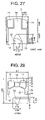
- FIG. 27 is a schematic diagram showing the air bearing surface configuration ABS 93 of a magnetic head slider as an example 5 for comparison.
- FIG. 28 is a schematic diagram showing the air bearing surface configuration ABS 94 of a magnetic head slider as an example 6 for comparison.
- FIG. 29 is a schematic diagram showing the air bearing surface configuration ABS 95 of a magnetic head slider as an example 7 for comparison.
- FIG. 30 is a schematic diagram showing the air bearing surface configuration ABS 96 of a magnetic head slider as an example 8 for comparison.
- FIG. 31 is a schematic diagram showing the air bearing surface configuration ABS 97 of a magnetic head slider as an example 9 for comparison.
- FIG. 32 is a schematic diagram showing the air bearing surface configuration ABS 98 of a magnetic head slider as an example 10 for comparison.
- FIG. 34 is a graph showing a calculation result of a fluctuation ⁇ h 2 in a flying height h 2 at the slider trailing edge with respect to a ratio of contact surface areas of the leading and trailing pads, S/S 1 .
- FIG. 35 is a side view for explaining the working of the magnetic head slider and its support of the second embodiment of the invention.
- FIG. 36A is a plan view showing an embodiment of a magnetic disk unit according to the invention, and FIG. 36B is a side view thereof.
- the above construction reduces the absolute value of a subambient pressure force on the back side of the slider, making it possible to reduce the contact area of each pad.
- This provides the slider which, if there is a waviness such as runout on the disk surface, follows the surface waviness without contacting the disk and keeps a low flying height and which has small fluctuations in the flying height.
- FIG. 1 is a perspective view of the magnetic head slider and its support according to the first embodiment of the invention.
- FIG. 2A and FIG. 2B are a perspective view and a side view, respectively, of the magnetic head slider of the first embodiment of the invention.
- the slider 1 is comprised of a slider body 1 a, two (paired) pads 11 formed on the air inflow side, which may serve as air bearing surfaces (also referred to as leading trailing pads hereinafter), the pad 12 formed on the air outflow side, which may serve as an air bearing surface (also referred to as a trailing pad hereinafter), and a pair of side rails 13 formed along both sides of the slider.
- a write/read element 1 b comprised of an exposed portion of an MR element of an MR (magneto-resistive) read head and a gap portion of an electromagnetic induction type write head are provided. Further, on a rear end surface of the slider 1 , a magnetic head 1 c and connection terminals 1 d are provided.
- the slider 1 is a subambient pressure force utilizing type slider in which a subambient pressure force Q 2 is produced in a recess 14 enclosed by the two leading pads 11 , which aerodynamically generates a positive pressure force Q 1 , and by the pair of side rails 13 .
- the subambient pressure force Q 2 is produced because, as the disk turns, air flows in between the slider and the disk and rapidly expands in volume in the recess 14 .
- the positive pressure force Q 1 acts to increase the flying height
- the subambient pressure force Q 2 acts to lower the flying height.
- the leading pad 11 , the side rail 13 and the trailing pad 12 in the first embodiment of the invention are shown. These are defined by a pad surface 112 (contact surface), which contacts the media surface when the disk is at rest, and two stepped surfaces, a first stage stepped surface 114 (step surface) provided on the air inflow side and a second stage stepped surface 116 (recessed surface) provided with stepped portions 113 , 115 interposed therebetween.
- ⁇ s 1 represents a depth of the stepped surface 114 from the pad surface 112 of the leading pad 11 (step depth), ⁇ s 3 a depth of the side rail 13 from the pad surface 112 (step depth), ⁇ s 2 a depth of the stepped surface 114 from the pad surface 112 of the trailing pad 12 (step depth), and ⁇ r a depth of the stepped surface 116 from the pad surface 112 (recess depth).
- leading pad step depth ⁇ s 1 , the trailing pad step depth ⁇ s 2 , and the side rail step depth ⁇ s 3 are set to increase in the order of ⁇ s 1 , ⁇ s 2 and ⁇ s 3 .
- S 1 and S represent the areas of the contact surfaces of the leading pad 11 and the trailing pad 12 , respectively.
- FIG. 5 shows a plan view of the magnetic head slider support (also called as a suspension) of this embodiment.
- the support 2 is comprised of a load beam portion 21 , a gimbal portion 22 , a load protrusion portion (also called as dimple) 23 , etc.
- FIGS. 6A and 6B are side views showing the magnetic head slider of this embodiment as it flies and runs.
- the dimple 23 is provided as a load exerting point through which a load F applied from the load beam portion 21 acts on the slider.
- This dimple also serves as a fulcrum through which the slider is applied a righting moment with respect to its movements of three degrees of freedom in a translation (vertical) direction, in a pitch (longitudinal) direction and in a roll (seek) direction.
- FIG. 7 shows the air bearing surface configuration (ABS 1 ) of the magnetic head slider of this embodiment.
- the slider is of a pico-size having a length L of 1.25 mm.
- the suspension preload F is 1.4 mN
- the dimple positions xp/L and yp/L are both 0.5.
- the length L 112 of the contact surface 112 of the trailing pad 12 is 0.225
- the length L 114 of the stepped surface 114 relative to the pad surface 112 of the trailing pad 12 is 0.421
- the length L 13 of the side rails 13 is 0.595
- the ratio of an area S of the trailing pad contact surface 112 to the area S 1 of the leading pad contact surface 112 is 0.164.
- FIG. 8 shows a calculation result of, for the air bearing surface configuration ABS 1 , a fluctuation ⁇ h 2 in the flying height h 2 at the slider trailing edge with respect to a ratio of the trailing pad step depth ⁇ s 2 to the leading pad step depth ⁇ s 1 , ⁇ s 2 / ⁇ s 1 , when the slider is running over a media surface that has a waviness of a long wavelength compared with the slider length and a large amplitude, such as runout.
- the ratio of the side rail step depth ⁇ s 3 to the leading pad step depth ⁇ s 1 , ⁇ s 3 / ⁇ s 1 was changed as shown in FIG. 9 .
- the flying height increases. That is, the reason why the flying height increases when ⁇ s 2 / ⁇ s 1 and ⁇ s 3 / ⁇ s 1 increase is that the increase in ⁇ s 2 / ⁇ s 1 and ⁇ s 3 / ⁇ s 1 causes the absolute value of the subambient pressure force Q 2 to decrease.
- FIG. 11 shows a calculation result of, for the air bearing surface configuration ABS 1 , a fluctuation in the minimum flying height hmin due to a geometrically unfollowable microwaviness of a wavelength almost equal to the slider length and a small amplitude with respect to ⁇ s 2 / ⁇ s 1 .
- FIG. 12 shows a calculation result of, for the air bearing surface configuration ABS 1 , a reduction in the minimum flying height hmin with respect to ⁇ s 2 / ⁇ s 1 when an atmospheric pressure around the slider changes from an altitude of 0 m to an altitude of 3000 m.
- FIG. 13 shows the air bearing surface ABS 10 configuration of a magnetic head slider as an example 1 for comparison.
- the slider is of a pico-size having a length L of 1.25 mm. Its step depths ⁇ s 1 , ⁇ s 2 , ⁇ s 3 are equal to each other.
- the ratio of an area S of the contact surface 112 of the trailing pad 12 to an area S 1 of the contact surface 112 of the leading pads 11 , S/S 1 is 0.303.
- FIG. 15A shows a calculation result of, for the air bearing surface configuration ABS 1 , a flying height h 2 at the slider trailing edge with respect to a ratio of the trailing pad step depth ⁇ s 2 to the leading pad step depth ⁇ s 1 , ⁇ s 2 / ⁇ s 1 .
- FIG. 15A it is seen that increasing ⁇ s 2 / ⁇ s 1 reduces the flying height h 2 at the slider trailing edge.
- FIG. 15B shows a calculation result of, for the air bearing surface configuration ABS 1 , a flying height h 2 at the slider trailing edge with respect to a ratio of the side rail step depth ⁇ s 3 to the leading pad step depth ⁇ s 1 , ⁇ s 3 / ⁇ s 1 .
- This calculation was made by assuming that the slider altitude was 0 m, that a revolution speed and a radius position were those at the innermost circumference of a 2.5-inch disk unit, and that the leading pad step depth ⁇ s 1 and the trailing pad step depth ⁇ s 2 were both held constant at 0.18 ⁇ m.
- FIG. 15B it is seen that when ⁇ s 3 / ⁇ s 1 is increased, the flying height h 2 at the slider trailing edge increases.
- This invention successfully reduces the flying height fluctuation due to caused by a media surface waviness of a long wavelength, such as runout, by increasing ⁇ s 2 / ⁇ s 1 and ⁇ s 3 / ⁇ s 1 under the condition of hgap kept almost constant.
- This arrangement also reduces geometrically the flying height fluctuation caused by a microwaviness of a wavelength almost equal to that of the slider length and a small amplitude.
- FIG. 16A and FIG. 16B show a perspective view and a side view of the magnetic head slider according to the second embodiment of the invention.
- the slider 1 is comprised of two (paired) leading pads 11 formed on the air inflow side, a trailing pad 12 formed on the air outflow side, and a pair of side rails 13 formed along the lateral sides.
- a write/read element 1 b comprising an exposed portion of an MR element of an MR read head and a gap portion of an electromagnetic induction type write head is provided, and on a rear end surface of the slider 1 , a magnetic head 1 c and connection terminals 1 d are provided.
- the step depth of the leading pads 11 , ⁇ s 1 , the step depth of the trailing pad 12 , ⁇ s 2 , and the step depth of the side rails 13 , ⁇ s 3 are set such that ⁇ s 1 and ⁇ s 2 are equal and ⁇ s 3 is larger than ⁇ s 1 and ⁇ s 2 .
- FIGS. 17A and 17B show air bearing surface configurations ABS 21 , ABS 22 for the magnetic head slider of this embodiment.
- the slider is of a pico-size having a length L of 1.25 mm.
- the suspension preload F is 29.9 mN, the dimple positions xp/L and yp/L are both 0.5.
- the length L 112 of the contact surface 112 of the trailing pad 12 is 0.185 for ABS 21 and 0.145 for ABS 22
- the length L 114 of the stepped surface 114 of the trailing pad 12 is 0.381 for ABS 21 and 0.341 for ABS 22 .
- FIG. 18 shows a calculation result of a fluctuation ⁇ h 2 in the flying height h 2 at the slider trailing edge with respect to a ratio of the side rail step depth ⁇ s 3 to the leading pad step depth ⁇ s 1 , ⁇ s 3 / ⁇ s 1 , when the slider is running over a media surface waviness of a long wavelength compared with the slider length and a large amplitude, such as runout.
- the method of calculating the fluctuation in the minimum flying height hmin in the 2.5-, 1.8- and 1.0-inch disk unit is the same as that shown in FIG. 11 . From FIG. 19 and FIG. 21 , it is seen that reducing the S/S 1 and increasing the ⁇ s 3 / ⁇ s 1 can reduce the fluctuation in the minimum flying height hmin due to a geometrically unfollowable microwaviness of a wavelength almost equal to the slider length. This effect is greater for 1.8- and 1.0-inch disk units with smaller radii.
- FIG. 22 shows a calculation result of a reduction in the minimum flying height hmin with respect to ⁇ s 3 / ⁇ s 1 when an atmospheric pressure around the slider changes from 0 m in altitude to 3000 m.
- This relation was calculated under the conditions that a slider altitude was 0 m, that a revolution speed and a radius position were those at the innermost circumference of a 2.5-inch disk unit, that the element position flying height hgap was 12.2–12.4 nm, and that the leading pad step depth ⁇ s 1 and the trailing pad step depth ⁇ s 2 were both held constant at 0.18 ⁇ m.
- FIG. 22 shows a calculation result of a reduction in the minimum flying height hmin with respect to ⁇ s 3 / ⁇ s 1 when an atmospheric pressure around the slider changes from 0 m in altitude to 3000 m.
- FIG. 23A shows the air bearing surface configuration ABS 11 of a magnetic head slider as an example 2 for comparison.
- the slider is of a pico-size having a length L of 1.25 mm.
- the suspension preload F is 29.4 mN, and the dimple positions xp/L, yp/L are both 0.5.
- the length L 112 of the contact surface 112 of the trailing pad 12 is 0.225 mm
- the length L 114 of the stepped surface 114 of the trailing pad 12 is 0.421 mm
- the length L 13 of the side rails 13 is 0.239 mm
- the ratio of an area S 1 of the contact surface 112 of the trailing pad 12 to an area S 1 of the contact surface 112 of the leading pads 11 , S/S 1 is 0.164.
- the length L 13 of the side rails 13 of the air bearing surface configuration ABS 11 is 0.356 mm shorter than that of ABS 1 and other geometries of the ABS 11 are the same as those of ABS 1 .
- the step depths ⁇ s 1 , ⁇ s 2 , ⁇ s 3 are equal.
- FIG. 23B shows a calculation result of a reduction in the hmin when an atmospheric pressure around the slider changes from 0 m in altitude to 3000 m under the condition that a revolution speed and a radius position are those at the innermost and outermost circumferences of a 2.5-inch disk unit.
- the hmin reduction was calculated for two cases. In the first case, for the air bearing surface configuration ABS 1 of the second embodiment, the minimum flying height hmin is increased by increasing the ratio of the side rail step depth ⁇ s 3 to the leading pad step depth ⁇ s 1 , ⁇ s 3 / ⁇ s 1 , with ⁇ s 2 / ⁇ s 1 set to 1.
- FIG. 24 shows that, for the same hmin, the hmin reduction due to the atmospheric pressure change when the hmin is increased by increasing ⁇ s 3 / ⁇ s 1 of the second embodiment is smaller than the hmin reduction when the hmin is increased by reducing the side rail length of the comparison example.
- FIG. 24A shows that, for the same hmin, the ⁇ p change caused by the atmospheric pressure change when the hmin is increased by increasing ⁇ s 3 / ⁇ s 1 of the second embodiment is larger than the ⁇ p change when the hmin is increased by reducing the side rail length of the comparison example.
- FIG. 25 to FIG. 33 show the air bearing surface configurations ABS 91 – 99 of magnetic head sliders as examples 3–11 for comparison.
- the air bearing surfaces ABS 91 – 93 , 95 – 97 , 99 are of a pico-size having a slider length L of 1.25 mm, and the air bearing surface configurations ABS 94 , 98 are of a femto-size having a slider length L of 0.85 mm.
- Ratios of an area S of the contact surface 112 of the trailing pad 12 to an area S 1 of the contact surface 112 of the leading pads 11 , S/S 1 , for the air bearing surface configurations ABS 91 – 99 are 0.460, 0.398, 0.335, 0.260, 0.253, 0.190, 0.178, 0.144, and 0.128 respectively.
- the step depths ⁇ s 1 , ⁇ s 2 , ⁇ s 3 for ABS 91 – 99 are all equal to each other.
- FIG. 34 shows a calculation result of a fluctuation ⁇ h 2 in the flying height h 2 at the slider trailing edge with respect to S/S 1 when the slider is running over a medium surface waviness of a longer-than-slider-length wavelength and a large amplitude, such as runout. This was calculated by assuming that the slider altitude was 0 m and that a revolution speed and a radius position were those at the innermost circumference of a 2.5-inch disk unit, and that the flying height h 2 at the slider trailing edge was 9.2–9.9 nm. The method of calculating ⁇ h 2 is the same as that shown in FIG. 8 .
- FIGS. 36A and 36B show an embodiment of a magnetic disk unit according to the invention.
- the magnetic disk unit 30 of the figure is in a state where the slider 1 is running and in a seeking operation while flying above the surface of a recording medium 3 .
- the magnetic disk unit 30 of this embodiment is comprised of a magnetic recording medium 3 , a drive unit 31 for rotating the medium, a support arm 32 for positioning the magnetic head slider 1 of this invention and its support 2 , a drive unit 33 for the support arm 32 , and a circuit 34 for processing write/read signals to and from the magnetic head mounted on the slider 1 .
- the magnetic head slider 1 mounted in this magnetic disk unit is constructed such that the leading pad step depth ( ⁇ s 1 ) of the slider, the trailing pad step depth ( ⁇ s 2 ) and the side rail step depth ( ⁇ s 3 ) with respect to the contact surfaces of the slider and disk are in a relation of ⁇ s 1 ⁇ s 2 ⁇ s 3 , and with this construction, the slider, which may follow the waviness of the disk surface and maintain a low flying height while having a small flying height fluctuation, can be provided.
- the support therefor and the magnetic disk unit by appropriately specifying the leading pad step depth, the side rail step depth of the slider, etc., a flying height fluctuation with respect to a media surface waviness of a long wavelength such as runout is reduced without reducing the slider flying height, and thereby a slider flying characteristic, which is suited to a high areal density of the media surface, can be provided.
Landscapes
- Adjustment Of The Magnetic Head Position Track Following On Tapes (AREA)
Abstract
Description
Claims (12)
Applications Claiming Priority (2)
| Application Number | Priority Date | Filing Date | Title |
|---|---|---|---|
| JP2002066388A JP2003263709A (en) | 2002-03-12 | 2002-03-12 | Magnetic head slider, its support and magnetic disk drive |
| JP2002-066388 | 2002-03-12 |
Publications (2)
| Publication Number | Publication Date |
|---|---|
| US20030218832A1 US20030218832A1 (en) | 2003-11-27 |
| US7038883B2 true US7038883B2 (en) | 2006-05-02 |
Family
ID=29198197
Family Applications (1)
| Application Number | Title | Priority Date | Filing Date |
|---|---|---|---|
| US10/385,674 Expired - Fee Related US7038883B2 (en) | 2002-03-12 | 2003-03-12 | Magnetic head slider, support therefor and magnetic disk unit |
Country Status (2)
| Country | Link |
|---|---|
| US (1) | US7038883B2 (en) |
| JP (1) | JP2003263709A (en) |
Cited By (4)
| Publication number | Priority date | Publication date | Assignee | Title |
|---|---|---|---|---|
| US20040201924A1 (en) * | 2003-04-10 | 2004-10-14 | Alps Electric Co., Ltd. | Magnetic head apparatus having magnetic head slider and magnetic disk apparatus equipped with magnetic head apparatus |
| US20050207065A1 (en) * | 2004-02-10 | 2005-09-22 | Matsushita Elec. Ind. Co. Ltd. | Slider and magnetic disk unit |
| US20080158716A1 (en) * | 2006-12-28 | 2008-07-03 | Fujitsu Limited | Head slider |
| US20080239573A1 (en) * | 2005-01-26 | 2008-10-02 | Zhisheng Deng | Head Slider, Head Support Unit and Disk Drive Apparatus |
Families Citing this family (6)
| Publication number | Priority date | Publication date | Assignee | Title |
|---|---|---|---|---|
| JP4139700B2 (en) * | 2003-01-30 | 2008-08-27 | 株式会社日立グローバルストレージテクノロジーズ | Magnetic head slider and magnetic disk device |
| US7233460B2 (en) * | 2003-07-08 | 2007-06-19 | Sae Magnetics (H.K.) Ltd. | Ultra-low flying height slider design |
| JP2005285217A (en) * | 2004-03-29 | 2005-10-13 | Toshiba Corp | Slider, head assembly, disk device |
| JP2005353188A (en) * | 2004-06-11 | 2005-12-22 | Hitachi Global Storage Technologies Netherlands Bv | Magnetic disk unit |
| JP2006120228A (en) * | 2004-10-20 | 2006-05-11 | Toshiba Corp | Disk unit |
| US20080158724A1 (en) * | 2006-12-28 | 2008-07-03 | Dorius Lee K | Slider air bearing for mobile drives |
Citations (1)
| Publication number | Priority date | Publication date | Assignee | Title |
|---|---|---|---|---|
| US20020008939A1 (en) * | 2000-04-12 | 2002-01-24 | Boutaghou Zine Eddine | Pad design concepts for slider air-bearings |
-
2002
- 2002-03-12 JP JP2002066388A patent/JP2003263709A/en active Pending
-
2003
- 2003-03-12 US US10/385,674 patent/US7038883B2/en not_active Expired - Fee Related
Patent Citations (1)
| Publication number | Priority date | Publication date | Assignee | Title |
|---|---|---|---|---|
| US20020008939A1 (en) * | 2000-04-12 | 2002-01-24 | Boutaghou Zine Eddine | Pad design concepts for slider air-bearings |
Cited By (6)
| Publication number | Priority date | Publication date | Assignee | Title |
|---|---|---|---|---|
| US20040201924A1 (en) * | 2003-04-10 | 2004-10-14 | Alps Electric Co., Ltd. | Magnetic head apparatus having magnetic head slider and magnetic disk apparatus equipped with magnetic head apparatus |
| US7145752B2 (en) * | 2003-04-10 | 2006-12-05 | Alps Electric Co., Ltd. | Magnetic head apparatus having magnetic head slider and magnetic disk apparatus equipped with magnetic head apparatus |
| US20050207065A1 (en) * | 2004-02-10 | 2005-09-22 | Matsushita Elec. Ind. Co. Ltd. | Slider and magnetic disk unit |
| US7339765B2 (en) * | 2004-02-10 | 2008-03-04 | Matsushita Electric Industrial Co., Ltd. | Slider with air bearing surface with selected distances between recording/reproducing element and rear-rail for reducing variation in flying height |
| US20080239573A1 (en) * | 2005-01-26 | 2008-10-02 | Zhisheng Deng | Head Slider, Head Support Unit and Disk Drive Apparatus |
| US20080158716A1 (en) * | 2006-12-28 | 2008-07-03 | Fujitsu Limited | Head slider |
Also Published As
| Publication number | Publication date |
|---|---|
| JP2003263709A (en) | 2003-09-19 |
| US20030218832A1 (en) | 2003-11-27 |
Similar Documents
| Publication | Publication Date | Title |
|---|---|---|
| US5396386A (en) | Roll insensitive air bearing slider | |
| US5737151A (en) | Roll insensitive air bearing slider | |
| CA1311838C (en) | Magnetic head air bearing slider | |
| US4734803A (en) | Magnetic head air bearing slider | |
| US5062017A (en) | Hour-glass disk head slider | |
| US6700727B1 (en) | Slider and method for actively controlling crown curvature | |
| US6452752B1 (en) | Slider for disc storage system | |
| US5870250A (en) | Method and apparatus for improving file capacity using different flying height profiles | |
| US6590746B2 (en) | Negative pressure air-lubricated bearing slider | |
| US6411468B1 (en) | Pseudo-contact negative pressure air bearing slider with dual negative pressure pockets and central transducer | |
| US6021024A (en) | Magnetic disk drive having a constant skew angle | |
| US6072662A (en) | Magnetic head slider with U-shaped and/or V-shaped portions | |
| EP0936599B1 (en) | Flying negative pressure air bearing slider with divided negative pressure pockets | |
| US20060023358A1 (en) | Method and apparatus for providing a three step air bearing with improved fly height performance | |
| US5550692A (en) | Proximity recording air bearing slider design with waist offset | |
| US7038883B2 (en) | Magnetic head slider, support therefor and magnetic disk unit | |
| US5761004A (en) | Air bearing slider with offset crossbars to reduce roll | |
| US5825587A (en) | Shallow etch air bearing surface features for optimized transducer spacing | |
| JP3243698B2 (en) | Negative pressure floating head slider and rotating disk storage device | |
| US5825588A (en) | Roll insensitive air bearing slider | |
| US7042678B2 (en) | Magnetic head slider and magnetic disc unit | |
| US6574074B2 (en) | Air bearing surface design for inducing roll-bias during load/unload sequence | |
| CN1577594B (en) | Ultra low flying height slider and design method | |
| US6597536B2 (en) | Magnetic head slider | |
| JPH07111053A (en) | Magnetic disk unit |
Legal Events
| Date | Code | Title | Description |
|---|---|---|---|
| AS | Assignment |
Owner name: HITACHI, LTD., JAPAN Free format text: ASSIGNMENT OF ASSIGNORS INTEREST;ASSIGNORS:TSUCHIYAMA, RYUJI;KOHIRA, HIDEKAZU;MATSUMOTO, MASAAKI;AND OTHERS;REEL/FRAME:014249/0041;SIGNING DATES FROM 20030224 TO 20030303 |
|
| AS | Assignment |
Owner name: HITACHI GLOBAL STORAGE TECHNOLOGIES JAPAN, LTD., J Free format text: ASSIGNMENT OF ASSIGNORS INTEREST;ASSIGNOR:HITACHI, LTD.;REEL/FRAME:015642/0704 Effective date: 20050120 |
|
| FEPP | Fee payment procedure |
Free format text: PAYOR NUMBER ASSIGNED (ORIGINAL EVENT CODE: ASPN); ENTITY STATUS OF PATENT OWNER: LARGE ENTITY |
|
| FPAY | Fee payment |
Year of fee payment: 4 |
|
| FEPP | Fee payment procedure |
Free format text: PAYER NUMBER DE-ASSIGNED (ORIGINAL EVENT CODE: RMPN); ENTITY STATUS OF PATENT OWNER: LARGE ENTITY Free format text: PAYOR NUMBER ASSIGNED (ORIGINAL EVENT CODE: ASPN); ENTITY STATUS OF PATENT OWNER: LARGE ENTITY |
|
| REMI | Maintenance fee reminder mailed | ||
| LAPS | Lapse for failure to pay maintenance fees | ||
| STCH | Information on status: patent discontinuation |
Free format text: PATENT EXPIRED DUE TO NONPAYMENT OF MAINTENANCE FEES UNDER 37 CFR 1.362 |
|
| STCH | Information on status: patent discontinuation |
Free format text: PATENT EXPIRED DUE TO NONPAYMENT OF MAINTENANCE FEES UNDER 37 CFR 1.362 |
|
| FP | Lapsed due to failure to pay maintenance fee |
Effective date: 20140502 |