US7032453B2 - Method and apparatus for the diagnosis of natural vibrations in a mechatronic system - Google Patents
Method and apparatus for the diagnosis of natural vibrations in a mechatronic system Download PDFInfo
- Publication number
- US7032453B2 US7032453B2 US10/478,898 US47889803A US7032453B2 US 7032453 B2 US7032453 B2 US 7032453B2 US 47889803 A US47889803 A US 47889803A US 7032453 B2 US7032453 B2 US 7032453B2
- Authority
- US
- United States
- Prior art keywords
- drive
- natural vibrations
- sensors
- rigid body
- module
- Prior art date
- Legal status (The legal status is an assumption and is not a legal conclusion. Google has not performed a legal analysis and makes no representation as to the accuracy of the status listed.)
- Expired - Lifetime, expires
Links
- 238000003745 diagnosis Methods 0.000 title claims abstract description 28
- 238000000034 method Methods 0.000 title claims abstract description 21
- 230000010355 oscillation Effects 0.000 claims description 6
- 238000012545 processing Methods 0.000 claims description 6
- 238000006073 displacement reaction Methods 0.000 description 6
- 230000001133 acceleration Effects 0.000 description 4
- 238000012800 visualization Methods 0.000 description 4
- 230000000694 effects Effects 0.000 description 2
- 239000000463 material Substances 0.000 description 2
- NJPPVKZQTLUDBO-UHFFFAOYSA-N novaluron Chemical compound C1=C(Cl)C(OC(F)(F)C(OC(F)(F)F)F)=CC=C1NC(=O)NC(=O)C1=C(F)C=CC=C1F NJPPVKZQTLUDBO-UHFFFAOYSA-N 0.000 description 2
- 230000002411 adverse Effects 0.000 description 1
- 238000013459 approach Methods 0.000 description 1
- 239000003086 colorant Substances 0.000 description 1
- 238000007796 conventional method Methods 0.000 description 1
- 238000013461 design Methods 0.000 description 1
- 238000001514 detection method Methods 0.000 description 1
- 238000010586 diagram Methods 0.000 description 1
- 230000005284 excitation Effects 0.000 description 1
- 230000002401 inhibitory effect Effects 0.000 description 1
- 238000004519 manufacturing process Methods 0.000 description 1
- 238000013178 mathematical model Methods 0.000 description 1
- 238000005259 measurement Methods 0.000 description 1
- 238000012986 modification Methods 0.000 description 1
- 230000004048 modification Effects 0.000 description 1
- 238000004806 packaging method and process Methods 0.000 description 1
- 238000004088 simulation Methods 0.000 description 1
- 238000013519 translation Methods 0.000 description 1
Images



Classifications
-
- G—PHYSICS
- G01—MEASURING; TESTING
- G01M—TESTING STATIC OR DYNAMIC BALANCE OF MACHINES OR STRUCTURES; TESTING OF STRUCTURES OR APPARATUS, NOT OTHERWISE PROVIDED FOR
- G01M7/00—Vibration-testing of structures; Shock-testing of structures
Definitions
- the invention relates to a method for the diagnosis of natural vibrations in a mechatronic system, for example a machine tool, packaging machine and other manufacturing machines, e.g. in the form of a robot.
- mechatronic systems normally include a plaurality of machine elements, including drives, which cause unwanted vibrations during operation of the system.
- Each one of these vibrations results from a combination of forced vibrations, caused by external forces or unbalances for example, as well as from natural vibrations which are encountered when one or more of the resonances of the machine are excited.
- These vibrations adversely affect the quality of products produced by the mechatronic system, so that ways to substantially reduce these vibrations are searched for.
- vibration diagnosis is to make the technical designer of a mechatronic system understand as clearly as possible the vibration behavior of the system in order to give him a tool to use constructive measures and/or select materials for inhibiting vibration.
- a mathematical model of the vibration behavior of the overall system can be formed on the basis of the measured values. As all system components are, however, interconnected, a system of coupled differential equations is obtained which are converted by means of model analysis, i.e. by means of an algorithmic mathematical uncoupling, into different scalar equations, so that information can be provided about the natural frequency, the attenuation, and form of the vibration for each mode of a natural vibration.
- a model of the mechatronic system can be simulated and visualized by means of a simple wire-frame model for example.
- wire-frame models are conventional and are constituted by corner points where sensors are typically attached in such a manner that a maximum yield of information is obtainer.
- the design engineer thus is given insight into the system dynamics and can take vibration-absorbing constructive measures through modification of the oscillation parameters that are now known.
- This object is attained by a method for the diagnosis of natural vibrations of a mechatronic system, wherein the system includes at least one rigid body which is movable relative to another rigid body by at least one numerically-controlled drive, wherein the natural vibrations are excited by the drive and detected by sensors.
- the need for a system-external shaker is eliminated which is no longer required because the drives assume their task.
- the drives as additional rotatory shakers, the eleectro-mechanic properties of the drives can enter into the integrated mechatronic modelling so that the afore-stated compliances between mechanical structure and drives can be better ascertained.
- the drive which runs, for example, at a constant speed, is superimposed by white noise.
- White noise is used to excite the natural vibrations of the system.
- the natural vibrations of the system can also be excited by superimposing the speed at which the drive runs with sinusoidal vibrations of varying frequency.
- This method of known conventionally as “wobbling”.
- the described method allows a determination of the natural vibrations by means of system-internal sensors, such as, for example, displacement measuring systems, acceleration sensors, speed sensors, pressure measuring systems, etc.
- system-internal sensors such as, for example, displacement measuring systems, acceleration sensors, speed sensors, pressure measuring systems, etc.
- the vibration diagnosis can be carried out completely autarchic, i.e. with system-internal means, so long as the numerical control of the mechatronic system includes a respective hardware module and/or software module.
- the method can be enhanced by attaching to the mechatronic system additional sensors, like, for example, acceleration pick-ups
- additional sensors may be attached, when needed, or remain permanently on the system.
- the additional sensors may remain also on the system for simplification of these further diagnoses.
- the method can be carried out advantageously with an apparatus for the diagnosis of natural vibrations of a numerically-controlled mechatronic system, wherein the apparatus includes at least one rigid body which is moved relative to another rigid body by at least one numerically-controlled drive, wherein the numeric control of the system includes a hardware module and/or software module, wherein the hardware module and/or software module includes means for excitation of natural vibrations of the system by the numerically-controlled drives as well as means for processing the natural vibrations detected by the sensors.
- the module can be connected as external module to the numeric control.
- the numeric control would hereby only include the terminals for the module so that the module can be connected to the numeric control, when needed, i.e. for execution of the vibration diagnosis.
- compexity and costs of the numeric control can be kept low.
- the vibration diagnosis could then be carried out “on order” by a service expert, for example, by the service department of the supplier of the numeric control. In this case, there would even be no need for the customer to pay for the expenses for the module.
- the separate module may, however, also be designed in such a universal manner, as to be suitable for a wide variety of machines and numeric controls so that a single module can be used for the diagnosis of various mechatronic systems.
- the module may, however, also form an integral part of the numeric controls. This would simplify the repeated diagnosis of vibration of a mechatronic system.
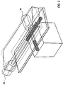
- FIG. 1 shows the wire-frame model or a machine tool
- FIGS. 2 , 3 and 4 show various vibrations models.
- FIG. 1 shows the wire-frame model of a machine tool with a pedestal S, a tool table arranged on the pedestal and including a table element WT 1 , movable in Y-direction, and a table element movable in X-direction.
- the table elements WT 1 and WT 2 are operated by the drives A 1 and A 2 and the pertaining spindles.
- the color boundary of the colors black and grey of the spindles designate the connection areas between the respective table element WT 1 , WT 2 and the spindles.
- the asymmetric illustration is caused by the generation of the wire-frame model which is defined by the corner points of the structural parts or components being viewed. In the present example, these corner points are so disposed as to be asymmetric.
- the shape of the wire-frame model should reflect the present geometry in a best possible manner through simplest basic elements.
- the areas are selected as corner points, such as, e.g., E 1 and E 2 , that also yield meaningful measuring information.
- displacement measuring systems WM 1 and WM 2 Attached to the components of the machine tool represented by the wire-frame model. These displacement measuring systems normally belong to the system-internal components of the actual machine tool. These additional displacement measuring systems may, of course, be provided, if required for the diagnosis of the natural vibrations.
- the speed sensors N 1 , N 2 of the drives A 1 , A 2 which are also present in the system, are also used as further sensors for the diagnosis of the natural vibrations.
- the machine tool is controlled by a numeric control NC which inlcudes for each drive an axis module AM 1 , AM 2 .
- a numeric control NC which inlcudes for each drive an axis module AM 1 , AM 2 .
- the numeric control regulates the drives A 1 , A 2 in a conventional manner.
- the numeric control NC is connected with a diagnosis module DM for vibration diagnosis.
- the diagnosis module DM may be a separate module which is implemented on a data processing machine, for example a laptop. It may, however, also form an integral part of the numeric control NC—as indicated also by the broken line.
- Diagnosis of the natural vibrations is realized by operating the drives A 1 , A 2 at constant speed nc, as illustrated in the graphical representation of the block diagram of the diagnistic module DM.
- This constant speed nc is superimposed with white noise—symbolized in the Figure by the sine curve.
- White noise contains all frequency portions and thus also those that excite the system to produce natural vibrations.
- the constant speed nc could also be superimposed with varying frequencies, whereby these varying frequencies are applied successively (wobbled).
- the natural vibrations of the mechatronic system are thereby reliably excited and can be detected by the displacement measuring systems WM 1 , WM 2 , the acceleration pick-ups BA 1 , BA 2 , and the speed sensors N 1 , N 2 .
- the vibration diagnosis determines also the continuously present compliances between the machine structure and the drives.
- Relaxation oscillations can be detected by suitably placing the sensors as far as possible also at the corner points of the rigid body. Sensors at the corner points E 1 and E 2 allow detection of, for example relaxation oscillations of the tool table WT 2 about the y-axis. The same is true for the sensors (not shown here) at further corner points, e.g. at the corner points of the tool table WT 1 .
- the results gained from the vibrations diagnosis allow a visualization of the vibration behavior of the mechatronic system by a wire-frame model, for example.
- the animation of the rotatory vibration modes in the space is gained from the combination of a three-dimensional linearized translation with a one-dimension rotation about a single axis.
- the vibration diagnosis is significantly simplfied by examining the effect of all machine elements partaking in the respective vibration mode and demonstrating it to the customer.
- An advantage that cannot be underestimated is hereby afforded for the acceptance of the measured results and possibly of the simulated results that have been suited to the measurements because clearer information can be made about the influence by the machine structure and the drives upon the dynamics of the mechatronic system.
- FIGS. 2 , 3 and 4 show some vibration modes by way of example at varying frequencies. The deformations are depicted by broken line so that they can be better visualized, and the difference compared to the undeformed state becomes clearer.
- the individual elements of the respective Figure are known from FIG. 1 .
- FIG. 2 shows a vibration mode at 56 Hertz
- FIG. 3 shows a vibration mode at 81 Hertz
- FIG. 4 shows a vibration mode at 106 Hertz.
- Each vibration mode on conventional mechatronic machines contains translatory as well as rotatory degrees of freedom whose separate consideration is of little value in view of a constant linkage between translatory and rotatory degrees of freedom.
- the procedure described herein fully considers this linkage from the mechatronic viewpoint by the simulatenous animation of all geometric basic elements, such as parallelepiped and cylinder, which represent the wire-frame model.
- reliable information is generated about the influence of rotatory and translatory degrees of freedom on the resultant vibration mode, when the drives are coupled in a compliant way to the mechanical structure.
- Shakers external to the system and acting translatory, can easily be integrated into the developed modal analysis tool for generating additional information.
Landscapes
- Physics & Mathematics (AREA)
- General Physics & Mathematics (AREA)
- Measurement Of Mechanical Vibrations Or Ultrasonic Waves (AREA)
- Testing Of Devices, Machine Parts, Or Other Structures Thereof (AREA)
Applications Claiming Priority (1)
| Application Number | Priority Date | Filing Date | Title |
|---|---|---|---|
| PCT/DE2001/003503 WO2003027627A1 (de) | 2001-09-12 | 2001-09-12 | Verfahren und vorrichtung zur diagnostik von eigenschwingungen eines mechatronischen systems |
Publications (2)
| Publication Number | Publication Date |
|---|---|
| US20040144177A1 US20040144177A1 (en) | 2004-07-29 |
| US7032453B2 true US7032453B2 (en) | 2006-04-25 |
Family
ID=5648284
Family Applications (1)
| Application Number | Title | Priority Date | Filing Date |
|---|---|---|---|
| US10/478,898 Expired - Lifetime US7032453B2 (en) | 2001-09-12 | 2001-09-12 | Method and apparatus for the diagnosis of natural vibrations in a mechatronic system |
Country Status (5)
| Country | Link |
|---|---|
| US (1) | US7032453B2 (de) |
| EP (1) | EP1425564B1 (de) |
| CN (1) | CN1280619C (de) |
| DE (1) | DE50115862D1 (de) |
| WO (1) | WO2003027627A1 (de) |
Cited By (1)
| Publication number | Priority date | Publication date | Assignee | Title |
|---|---|---|---|---|
| US20040225484A1 (en) * | 2003-03-13 | 2004-11-11 | Siemens Aktiengesellschaft | Measuring and simulation system for machine-tools or production machines |
Families Citing this family (10)
| Publication number | Priority date | Publication date | Assignee | Title |
|---|---|---|---|---|
| CN100339693C (zh) * | 2004-11-12 | 2007-09-26 | 哈尔滨工业大学 | 颗粒碰撞噪声检测仪的振动台驱动系统 |
| DE102006022595B3 (de) | 2006-05-15 | 2008-04-30 | Siemens Ag | Verfahren zum Überprüfen des Getriebeloses und Produktionsmaschine oder Roboter |
| DE102008004061A1 (de) * | 2008-01-12 | 2009-07-16 | Robert Bosch Gmbh | Spindeltrieb mit Lebensdauerüberwachung |
| US8255197B2 (en) * | 2008-09-30 | 2012-08-28 | Rockwell Automation Technologies, Inc. | Simulation of tuning effects for a servo driven mechatronic system |
| CN101806917A (zh) * | 2010-03-15 | 2010-08-18 | 哈尔滨工业大学 | 基于随机振动的密封电子元器件多余物的检测装置及方法 |
| DE102017207979B4 (de) * | 2017-05-11 | 2022-05-25 | Hiwin Technologies Corp. | Verfahren zum Schätzen einer Abweichung einer an eine lineare Führungsbahn angelegten Vorspannung |
| CN108507785B (zh) * | 2018-04-10 | 2019-12-24 | 西安交通大学 | 一种主轴回转状态下的动态特性测试装置及方法 |
| DE102019135488A1 (de) * | 2019-12-20 | 2021-06-24 | Trumpf Werkzeugmaschinen Gmbh + Co. Kg | Verfahren und System zur Ermittlung des dynamischen Verhaltens einer Maschine |
| DE102020134190B4 (de) | 2020-12-18 | 2025-12-04 | Rovema Gmbh | Verfahren zum Betrieb einer Schlauchbeutelmaschine |
| DE102023131910A1 (de) * | 2023-11-16 | 2025-05-22 | Bayerische Motoren Werke Aktiengesellschaft | Computerprogrammprodukt und Verfahren zur Animation von Schwingungen einer Vielzahl Strukturelemente einer Struktur |
Citations (11)
| Publication number | Priority date | Publication date | Assignee | Title |
|---|---|---|---|---|
| JPS61105438A (ja) | 1984-10-29 | 1986-05-23 | Nippon Denso Co Ltd | 振動試験装置 |
| US5602759A (en) | 1991-02-06 | 1997-02-11 | Honda Giken Kogyo Kabushiki Kaisha | Motor vehicle vibrating system |
| US5724893A (en) | 1996-10-15 | 1998-03-10 | Taichung Machinery Works Co. Ltd. | Servo-type shaking table assembly |
| US5812420A (en) * | 1995-09-05 | 1998-09-22 | Nikon Corporation | Vibration-preventive apparatus and exposure apparatus |
| US6036162A (en) * | 1996-09-10 | 2000-03-14 | Nikon Corporation | Vibration isolator and method of isolating vibration |
| CN1253623A (zh) | 1997-03-17 | 2000-05-17 | 株式会社日立制作所 | 振动激励装置和使用该装置的结构振动测试装置 |
| US6202492B1 (en) * | 1996-04-05 | 2001-03-20 | Nikon Corporation | Anti-vibration apparatus and exposure apparatus |
| US6213443B1 (en) * | 1998-05-07 | 2001-04-10 | Canon Kabushiki Kaisha | Anti-vibration apparatus and exposure apparatus using the same |
| US6286644B1 (en) * | 1999-01-18 | 2001-09-11 | Canon Kabushiki Kaisha | Active vibration isolator, exposure apparatus, exposure method and device manufacturing method |
| US20030057346A1 (en) * | 2000-09-14 | 2003-03-27 | Shinji Wakui | Active vibration isolator and exposure apparatus with the active vibration isolator, device manufacturing method |
| US6721668B1 (en) | 1997-03-17 | 2004-04-13 | Hitachi, Ltd. | Vibration exciting apparatus and vibration testing apparatus for structure using same |
Family Cites Families (4)
| Publication number | Priority date | Publication date | Assignee | Title |
|---|---|---|---|---|
| US3355933A (en) | 1964-03-16 | 1967-12-05 | Robert G Rowe | Resonance vibration testing apparatus |
| US3323352A (en) * | 1965-01-04 | 1967-06-06 | Branson Instr | Control circuit for resonant sensing device |
| HU172832B (hu) | 1976-04-27 | 1978-12-28 | Magyar Vagon Es Gepgyar | Sposob i izmeritel'noe ustrojstvo dlja kontrolja vibrogasjahhego ehffekta torzinnykh vibrogasitelej s kolebljajuhhimsja kol'com, napolnennykh vjazkoj zhidkost'ju |
| JPH03148032A (ja) * | 1989-11-06 | 1991-06-24 | Nikon Corp | 動揺度測定装置 |
-
2001
- 2001-09-12 WO PCT/DE2001/003503 patent/WO2003027627A1/de not_active Ceased
- 2001-09-12 CN CN01823520.4A patent/CN1280619C/zh not_active Expired - Fee Related
- 2001-09-12 US US10/478,898 patent/US7032453B2/en not_active Expired - Lifetime
- 2001-09-12 DE DE50115862T patent/DE50115862D1/de not_active Expired - Lifetime
- 2001-09-12 EP EP01274069A patent/EP1425564B1/de not_active Expired - Lifetime
Patent Citations (11)
| Publication number | Priority date | Publication date | Assignee | Title |
|---|---|---|---|---|
| JPS61105438A (ja) | 1984-10-29 | 1986-05-23 | Nippon Denso Co Ltd | 振動試験装置 |
| US5602759A (en) | 1991-02-06 | 1997-02-11 | Honda Giken Kogyo Kabushiki Kaisha | Motor vehicle vibrating system |
| US5812420A (en) * | 1995-09-05 | 1998-09-22 | Nikon Corporation | Vibration-preventive apparatus and exposure apparatus |
| US6202492B1 (en) * | 1996-04-05 | 2001-03-20 | Nikon Corporation | Anti-vibration apparatus and exposure apparatus |
| US6036162A (en) * | 1996-09-10 | 2000-03-14 | Nikon Corporation | Vibration isolator and method of isolating vibration |
| US5724893A (en) | 1996-10-15 | 1998-03-10 | Taichung Machinery Works Co. Ltd. | Servo-type shaking table assembly |
| CN1253623A (zh) | 1997-03-17 | 2000-05-17 | 株式会社日立制作所 | 振动激励装置和使用该装置的结构振动测试装置 |
| US6721668B1 (en) | 1997-03-17 | 2004-04-13 | Hitachi, Ltd. | Vibration exciting apparatus and vibration testing apparatus for structure using same |
| US6213443B1 (en) * | 1998-05-07 | 2001-04-10 | Canon Kabushiki Kaisha | Anti-vibration apparatus and exposure apparatus using the same |
| US6286644B1 (en) * | 1999-01-18 | 2001-09-11 | Canon Kabushiki Kaisha | Active vibration isolator, exposure apparatus, exposure method and device manufacturing method |
| US20030057346A1 (en) * | 2000-09-14 | 2003-03-27 | Shinji Wakui | Active vibration isolator and exposure apparatus with the active vibration isolator, device manufacturing method |
Cited By (2)
| Publication number | Priority date | Publication date | Assignee | Title |
|---|---|---|---|---|
| US20040225484A1 (en) * | 2003-03-13 | 2004-11-11 | Siemens Aktiengesellschaft | Measuring and simulation system for machine-tools or production machines |
| US7219041B2 (en) * | 2003-03-13 | 2007-05-15 | Siemens Aktiengesellschaft | Measuring and simulation system for machine-tools or production machines |
Also Published As
| Publication number | Publication date |
|---|---|
| EP1425564B1 (de) | 2011-04-20 |
| CN1551980A (zh) | 2004-12-01 |
| CN1280619C (zh) | 2006-10-18 |
| WO2003027627A1 (de) | 2003-04-03 |
| DE50115862D1 (de) | 2011-06-01 |
| EP1425564A1 (de) | 2004-06-09 |
| US20040144177A1 (en) | 2004-07-29 |
Similar Documents
| Publication | Publication Date | Title |
|---|---|---|
| US7975252B2 (en) | Reliability simulation method and system | |
| EP3082055B1 (de) | Drehflüglerkomponentensimulation mithilfe scan-basierter geometrie | |
| US20040144177A1 (en) | Method and device for the diagnosis of characteristic vibrations in a mechatronic system | |
| Mohamed et al. | Experimental validation of FEM-computed stress to tip deflection ratios of aero-engine compressor blade vibration modes and quantification of associated uncertainties | |
| JP7199793B2 (ja) | 異常検知システム、及び異常検知方法 | |
| Demilia et al. | Measurements for smart manufacturing in an Industry 4.0 scenario a case-study on a mechatronic system | |
| US20140324365A1 (en) | Method of assessing the technical condition of a rotating shaft | |
| WO2008129561A2 (en) | Real-time system and method for designing structures | |
| US20040093191A1 (en) | System and method for performing modal analysis of at least one remote structure | |
| CN114026403B (zh) | 机器状态的声学分析 | |
| CN114830052B (zh) | 用于确定机器的动态特性的方法和系统 | |
| JPH112643A (ja) | 加速度センサの周波数特性検査装置 | |
| CA2658687A1 (en) | Method for monitoring a production process | |
| JP3491105B2 (ja) | 数値制御工作機械 | |
| JP2003232703A (ja) | 異常診断装置 | |
| Venugopal | Component-Based Transfer Path Analysis and Hybrid Substructuring at high frequencies: A treatise on error modelling in Transfer Path Analysis | |
| KR100915720B1 (ko) | 기술 장비를 진단하기 위한 방법 | |
| KR20210104349A (ko) | 전동 컴프레서에 대한 딥러닝 기반 고장 진단 방법 및 장치 | |
| US20240242003A1 (en) | Computer implemented method of determining a transfer function of a module or a component and generating such component | |
| CN109264026A (zh) | 抗荷调压器动态物理性能试验设备 | |
| JPH07260564A (ja) | 回転機器の異常診断装置及び方法 | |
| JPS60108728A (ja) | 回転機械の振動特性試験装置 | |
| JP2025011379A (ja) | テストシステム | |
| Dias Jr et al. | Experimental analysis of the dynamic behaviour of a turbomachine foundation structure | |
| Wang | Experimental modal analysis and dynamic response of PC boards with surface mount electronic components |
Legal Events
| Date | Code | Title | Description |
|---|---|---|---|
| AS | Assignment |
Owner name: SIEMENS AKTIENGESELLSCHAFT, GERMANY Free format text: ASSIGNMENT OF ASSIGNORS INTEREST;ASSIGNORS:FLOCK, THOMAS;HAMANN, JENS;REEL/FRAME:015174/0968 Effective date: 20030915 |
|
| STCF | Information on status: patent grant |
Free format text: PATENTED CASE |
|
| FPAY | Fee payment |
Year of fee payment: 4 |
|
| FPAY | Fee payment |
Year of fee payment: 8 |
|
| MAFP | Maintenance fee payment |
Free format text: PAYMENT OF MAINTENANCE FEE, 12TH YEAR, LARGE ENTITY (ORIGINAL EVENT CODE: M1553) Year of fee payment: 12 |