US7019870B2 - Image forming apparatus - Google Patents
Image forming apparatus Download PDFInfo
- Publication number
- US7019870B2 US7019870B2 US10/076,651 US7665102A US7019870B2 US 7019870 B2 US7019870 B2 US 7019870B2 US 7665102 A US7665102 A US 7665102A US 7019870 B2 US7019870 B2 US 7019870B2
- Authority
- US
- United States
- Prior art keywords
- upper body
- range
- groove
- image forming
- link member
- Prior art date
- Legal status (The legal status is an assumption and is not a legal conclusion. Google has not performed a legal analysis and makes no representation as to the accuracy of the status listed.)
- Expired - Lifetime, expires
Links
- 238000007648 laser printing Methods 0.000 description 5
- 239000011521 glass Substances 0.000 description 4
- 238000000465 moulding Methods 0.000 description 2
- 239000004020 conductor Substances 0.000 description 1
- 230000005484 gravity Effects 0.000 description 1
- 238000009434 installation Methods 0.000 description 1
- 238000012986 modification Methods 0.000 description 1
- 230000004048 modification Effects 0.000 description 1
- 230000001105 regulatory effect Effects 0.000 description 1
Images


Classifications
-
- H—ELECTRICITY
- H04—ELECTRIC COMMUNICATION TECHNIQUE
- H04N—PICTORIAL COMMUNICATION, e.g. TELEVISION
- H04N1/00—Scanning, transmission or reproduction of documents or the like, e.g. facsimile transmission; Details thereof
- H04N1/00519—Constructional details not otherwise provided for, e.g. housings, covers
- H04N1/00551—Top covers or the like
- H04N1/00554—Latches or hinges therefor
-
- G—PHYSICS
- G03—PHOTOGRAPHY; CINEMATOGRAPHY; ANALOGOUS TECHNIQUES USING WAVES OTHER THAN OPTICAL WAVES; ELECTROGRAPHY; HOLOGRAPHY
- G03G—ELECTROGRAPHY; ELECTROPHOTOGRAPHY; MAGNETOGRAPHY
- G03G21/00—Arrangements not provided for by groups G03G13/00 - G03G19/00, e.g. cleaning, elimination of residual charge
- G03G21/16—Mechanical means for facilitating the maintenance of the apparatus, e.g. modular arrangements
- G03G21/1604—Arrangement or disposition of the entire apparatus
- G03G21/1623—Means to access the interior of the apparatus
- G03G21/1628—Clamshell type
-
- H—ELECTRICITY
- H04—ELECTRIC COMMUNICATION TECHNIQUE
- H04N—PICTORIAL COMMUNICATION, e.g. TELEVISION
- H04N1/00—Scanning, transmission or reproduction of documents or the like, e.g. facsimile transmission; Details thereof
- H04N1/00519—Constructional details not otherwise provided for, e.g. housings, covers
- H04N1/00543—Allowing easy access, e.g. for maintenance or in case of paper jam
-
- G—PHYSICS
- G03—PHOTOGRAPHY; CINEMATOGRAPHY; ANALOGOUS TECHNIQUES USING WAVES OTHER THAN OPTICAL WAVES; ELECTROGRAPHY; HOLOGRAPHY
- G03G—ELECTROGRAPHY; ELECTROPHOTOGRAPHY; MAGNETOGRAPHY
- G03G2221/00—Processes not provided for by group G03G2215/00, e.g. cleaning or residual charge elimination
- G03G2221/16—Mechanical means for facilitating the maintenance of the apparatus, e.g. modular arrangements and complete machine concepts
- G03G2221/1678—Frame structures
- G03G2221/1687—Frame structures using opening shell type machines, e.g. pivoting assemblies
-
- G—PHYSICS
- G03—PHOTOGRAPHY; CINEMATOGRAPHY; ANALOGOUS TECHNIQUES USING WAVES OTHER THAN OPTICAL WAVES; ELECTROGRAPHY; HOLOGRAPHY
- G03G—ELECTROGRAPHY; ELECTROPHOTOGRAPHY; MAGNETOGRAPHY
- G03G2221/00—Processes not provided for by group G03G2215/00, e.g. cleaning or residual charge elimination
- G03G2221/16—Mechanical means for facilitating the maintenance of the apparatus, e.g. modular arrangements and complete machine concepts
- G03G2221/18—Cartridge systems
- G03G2221/183—Process cartridge
Definitions
- the invention relates to an image forming apparatus that includes an upper body and a lower body and, more particularly to, an opening and closing movement of the upper body.
- a known image forming apparatus includes an image forming device that forms an image on a recording medium and an image reading device that reads an image on the original document.
- the image forming apparatus also includes an upper body and a lower body.
- the upper body is mounted on the lower body and connected to the lower body by a hinge.
- the upper body is pivoted about the hinge as a supporting point toward an open position and a close position with respect to the lower body.
- the image reading device is mounted in the upper body and the image forming device is mounted in the lower body.
- the image forming apparatus further includes a spring interposed between the upper body and the lower body. The spring urges the upper body toward the open position while an amount of deformation of the spring increases when the upper body is moved toward the close position. Strength of the spring is adjusted to a degree that the upper body is prevented from moving toward the close position by its own weight when the upper body is moved to the open position.
- the invention provides an image forming apparatus that improves a closing operation of an upper body and protects the upper body from an excessive stress.
- an image forming apparatus includes an upper body, an image reading device that is mounted in the upper body, a lower body that is placed under the upper body, an image forming device that is mounted in the lower body, a hinge member that connects the upper body and the lower body, at least one groove that is formed on the lower body, at least one link member that is connected to the upper body at one end and connected to the groove at the other end, and at least one elastic member that is connected to the lower body at one end and the link member at the other end.
- the image reading device reads an image on an original document.
- the image forming device forms the image on a recording medium.
- the upper body is pivoted about the hinge member between an open position where the upper body is open with respect to the lower body and a close position where the upper body is closed with respect to the lower body.
- the link member slides in the groove at the other end.
- the elastic member is deformed when the link moves together with the upper body, and an amount of deformation of the elastic member increases when the upper body is moved from the open position to the close position.
- the groove has a first range where a moment to pivot the upper body to the close position is generated.
- Various moments are generated to pivot the upper body in the image forming apparatus, such as a moment to pivot the upper body toward the close position by its own weight, and a moment to pivot the upper body toward the open position by a force exerted on the upper body via an elastic member and a link member.
- the moment to pivot the upper body toward the close position is generated when a sum of all moments acting on the upper body is a value by which the upper body is pivoted toward the close position.
- the moment to pivot the upper body toward the open position is generated when the sum of all moments acting on the upper body is a value by which the upper body is pivoted toward the open position.
- the moment to pivot the upper body toward the close position which is generated by the weight of the upper body, varies when a positional relationship between a center of rotation of the upper body and a center of gravity of the upper body changes as the upper body is pivoted.
- the moment to pivot the upper body toward the close position can be specified if a rotational angle of the upper body is determined.
- the moment to pivot the upper body toward the open position which is generated by a force acting on the upper body via the link member in accordance with a load of the elastic member, varies according to the center of rotation of the upper body, a connecting point between the upper body and the link member, a contact point between the link member and the groove, and an amount of deformation of the elastic member.
- the moment to pivot the upper body toward the open position can be regulated by changing the shape of the groove so as to optimize the contact point between the link member and the groove and a contact angle of each member at the contact point.
- the shape of the groove is determined in such a manner that the moment to pivot the upper body toward the close position is generated, based on the moment generated by the weight of the upper body.
- FIG. 1 is a perspective view of a laser printer according to an embodiment of the invention
- FIG. 2 is a perspective view of the laser printer when an upper body is in an open position
- FIG. 3 is a perspective view of a movable member of the laser printer
- FIG. 4A is a partial rear view of the laser printer when the upper body is in a close position
- FIG. 4B a sectional view of the laser printer when the upper body is in the close position
- FIG. 5 is a schematic illustration of a cam groove of the laser printer according to the embodiment of the invention.
- FIG. 6 is a schematic illustration of a cam groove of the laser printer according to another embodiment of the invention.
- FIG. 7 is a schematic illustration of a cam groove of the laser printer according to yet another embodiment.
- FIG. 8 is a partial sectional view of a link member and a spring of the laser printer when the upper body is in the close position;
- FIG. 9 is a partial sectional view of an engaging portion and an engaged portion of the laser printer.
- FIG. 10 is a sectional view of the link member and the spring of the laser printer when the upper body is in the open position;
- FIG. 11 is a sectional view of the laser printer when the upper body is in the open position
- FIG. 12A is a partial sectional view of an engaging portion according to another embodiment
- FIG. 12B is a partial sectional view of an engaging portion according to yet another embodiment.
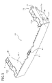
- FIG. 13 is a sectional view of a laser printer when an upper body is in a close position according to another embodiment.
- a laser printer 1 with an image scanner (hereinafter called as the printer 1 ) includes a laser printing mechanism 1 a mounted in a lower body 3 and an image scanner mechanism 1 b mounted in an upper body 5 .
- the lower body 3 and the upper body 5 are connected by hinges 7 that are provided apart on the backside of the printer 1 .
- the upper body 5 When the upper body 5 is pivoted upward about the hinges 7 as a supporting point, the upper body 1 moves toward an open position as shown in FIG. 2 .
- the upper body 5 is pivoted downward about the hinges 7 , the upper body 5 moves toward a close position as shown in FIG. 1 .
- An operating panel 9 is provided at the front side of the printer 1 .
- the laser printing mechanism la is structured where an image is formed on a recording sheet supplied from a sheet tray 11 provided at the backside of the printer 1 and the recording sheet is ejected from a discharge portion 13 provided at the front side of the printer 1 .
- a pullout discharge tray 15 is provided under the discharge portion 13 to receive recorded sheets discharged from the discharge portion 13 .
- the image scanner mechanism 1 b is of a flat bed type and includes a line type image sensor that moves along a platen glass (not shown) to read an image from an document placed on the platen glass.
- An automatic document feeder (hereinafter “ADF”) unit 17 is provided at the left side of the upper body 5 .
- the ADF unit 17 is structured to feed plural documents in order into the image scanner mechanism 1 b to read images therefrom. While documents are supplied one by one from a document feeding tray 21 into the ADF unit 17 , the image sensor becomes stationary and each document is sent over the image sensor to be scanned, so that image data can be obtained. Then the document is discharged from the ADF unit 17 and placed on a discharge tray 19 .
- the laser printing mechanism 1 a recording sheets are fed in a direction from rear to front of the printer 1 .
- the image scanner mechanism 1 b the image sensor moves in a lengthwise direction from left to right of the printer 1 .
- the two directions are arranged perpendicularly viewed from the top of the printer.
- An upper portion 3 a of the lower body 3 protrudes outwardly from a lower portion 3 b thereof and has the same size as the upper body 5 relative to a lengthwise moving direction of the image sensor.
- An impactive force to be generated when something comes into collision with the printer 1 is to be received by both the upper body 5 and the lower body 3 .
- the image scanner mechanism 1 b resists damage as compared with a structure where the upper body 5 only protrudes outwardly from the lower body 3 .
- a stepped portion 3 c is formed between the upper portion 3 a and the lower portion 3 b of the lower body 3 at each side. It is convenient to hold the printer 1 because the printer 1 can be supported manually from underneath at the stepped portion 3 c.
- the sheet tray 11 is disposed in a position such that it does not conflict with the upper body 5 when the upper body 5 is pivoted upward about the hinges 7 as the supporting point. The sheet tray 11 does not interfere with replacement of the cartridge 61 . Furthermore, the sheet tray 11 does not get damaged even if the upper body 5 is excessively pivoted toward the open position.
- the hinges 7 are provided on the back of the lower body 3 and upper body 5 so as to protrude rearward, and placed on both sides of the sheet tray 11 so as not to interfere with the sheet tray 11 .
- the sheet tray 11 can be arranged inclined. By inclining the sheet tray 11 , the convenience of operation for replenishing recording sheets into the sheet tray 11 can be increased.
- a movable member 23 is interposed between the lower body 3 and the upper body 5 .
- the movable member 23 is movably connected to the lower body 3 and upper body 5 .
- the movable member 23 is provided with a pair of link members 25 and a bridge 27 bridging the link members 25 , which are integrally formed into one body by molding.
- the movable member 23 can include only one link member 25 provided with or without a bridge 27 .
- Each of the link members 25 has a pair of walls 25 a , 25 b , which are formed parallel with each other.
- a cylindrical rotational shaft 31 and a cylindrical cam follower 33 are mounted on each wall 25 b facing outward so as to protrude therefrom.
- the rotational shaft 31 is rotatably mounted to a bearing 35 of the upper body 5 .
- the cam follower 33 is inserted into a cam groove 37 formed in the lower body 3 .
- a spring 39 is connected to each link member 25 between the walls 25 a , 25 b .
- the walls 25 a , 25 b prevent the spring 39 from being touched.
- the spring 39 is stretched between the lower body 3 and each link member 25 , and not connected to the upper body 5 .
- the upper body 5 is not deformed by the action of the spring 39 .
- the bridge 27 also serves as a part of exterior appearance when the upper body 5 is in the close position.
- the bridge 27 has a centermounted engaged portion 41 .
- the engaged portion 41 and the engaging portion 43 of the upper body 5 constitute a lock mechanism.
- the upper body 5 is locked with the lower body 3 .
- An operating lever 45 is integrally formed with the engaging portion 43 by molding.
- the operating lever 45 is pulled toward the front side of the printer 1 (in the direction of the arrow A in FIG. 9 )
- the engagement between the engaging portion 43 and the engaged portion 41 is released to unlock the upper body 5 .
- the upper body 5 is pulled upward, the upper body 5 is pivoted toward the open position as shown in FIG. 10 .
- the engaging portion 43 and the operating lever 45 are normally urged in a direction to engage with the engaged portion 41 by a resilient force generated by the spring 47 .
- the cam groove 37 has a first range 37 a , a second range 37 b , and a third range 37 c .
- the first range 37 a is provided to the front of the printer 1 .
- a resultant moment acting on the upper body 5 is exerted in a direction to close the upper body 5 .
- the second range 37 b is provided to the rear of the printer 1 .
- the resultant moment acting on the upper body 5 is exerted in a direction to open the upper body, contrary to the first range 37 a .
- the third range 37 c is provided in a position continuously connecting the first range 37 a and the second range 37 b . In the third range 37 c , a direction of the resultant moment acting on the upper body 5 is gradually changed.
- a force F produced by the weight of the upper body 5 acts on the rotational shaft 31 .
- the force F imposed on the rotational shaft 31 acts on the link member 25 .
- a force f is a resultant force of a force fx, which is produced tangentially with respect to the cam groove 37 by a load of the spring 39 that urges the link member 25 in a specified direction, and a force fy, which is a resistance acting vertically, generated at a contact point between the cam follower 33 and the cam groove 37 .
- the force F varies into force F 1 , F 2 , or F 3 according to the following rotational positions of the upper body 5 .
- the force F 1 is generated when the upper body 5 is closed
- the force F 2 is generated when the upper body 5 is opened
- the force F 3 is generated when the upper body 5 is at the midpoint position.
- the force f the resultant of forces fx and fy, varies into force f 1 , f 2 , or f 3 at the respective rotational positions of the upper body 5 .
- the forces f 1 , f 2 , f 3 are associated with the first range 37 a , the second range 37 b , and the third range 37 c , respectively.
- the resultant moment acting on the upper body 5 acts in the direction to close the upper body 5 .
- the first range 37 a is determined in such a manner to set the force F 1 greater than the force f 1 . Thereby, the moment is generated in the direction to close the upper body 5 .
- the second range 37 b In the second range 37 b , the moment acts in the direction to open the upper body 5 . Therefore, the second range 37 b is determined in such a manner to set forces f 2 , f 3 greater than forces F 2 , F 3 . Thereby, the moment is produced in the direction to open the upper body 5 .
- the upper body 5 When the upper body 5 is pivoted from the close position toward the open position so that the cam follower 33 reaches the second range 37 b in the cam groove 37 , the moment to pivot the upper body 5 toward the open position is generated.
- the upper body 5 is pivoted toward the open position, the cam follower 33 abuts against an end of the cam groove 37 , and the upper body 5 comes to rest.
- the upper body 5 can be kept at the open position without the need to be supported by a user, facilitating jobs performed in a space between the upper body 5 and the lower body 3 , such as repairing and adjustment of the printer 1 and replacement of the cartridge 61 .
- the cam groove 137 has a first range 137 a , a second range 137 b , and a third range 137 c .
- the first range 137 a is provided to the front of the printer 1 .
- the second range 137 b is provided to the rear of the printer 1 .
- the third range 137 c is provided in a position continuously connecting the first range 137 a and the second range 137 b .
- the moment acting on the upper body 5 is changed from the direction to close the upper body 5 to the direction to keep the balance.
- the upper body 5 can be prevented from pivoting toward the open position spontaneously. It is convenient when the upper body 5 can not be completely pivoted to the open position, for example, because the printer 1 is used where space is limited.
- the cam groove 237 includes a first range 237 a , a second range 237 b , a third range 237 c , a fourth range 237 d , a fifth range 237 e , a sixth range 237 f , and a seventh range 237 g .
- the first range 237 a is provided to the front of the printer 1 , where the moment acting on the upper body 5 is exerted in the direction to close the upper body 5 .
- the moment acting on the upper body 5 acts in the direction to open the upper body 5 .
- the moment acting on the upper body 5 acts in the direction to close the upper body 5 .
- the moment acting on the upper body 5 acts in the direction to open the upper body 5 .
- the fifth range 237 e is provided in a position continuously connecting the first range 237 a and the second range 237 b , where the direction of the moment acting on the upper body 5 is changed.
- the sixth range 237 f is provided in a position continuously connecting the second range 237 b and the third range 237 c , where the moment acting on the upper body 5 is not produced.
- the seventh range 237 g is provided in a position continuously connecting the third range 237 c and the fourth range 237 d , where the direction of the moment acting on the upper body 5 is changed.
- the upper body 5 Because the upper body 5 is held still while the cam follower 33 is in the sixth range 237 f , the upper body 5 can be prevented from pivoting toward the open position spontaneously. It is convenient when the upper body 5 can not be completely pivoted to the open position, for example, because the printer 1 is used where space is limited.
- the image scanner mechanism 1 b is of flat bed type and is accommodated in the upper body 5 .
- the image scanner mechanism 1 b includes the line type image sensor 8 , which is movably mounted on a rail 10 .
- the line type image sensor 8 moves along the platen glass 9 and reads image from a document placed on the platen glass 9 .
- the laser printing mechanism la has a scanner unit 51 , a photosensitive drum 53 , a developing roller 55 , a toner cartridge 62 , a toner supply roller 63 , the sheet roller 56 , a transfer roller 57 and a fixing unit 59 .
- the scanner unit 51 emits a laser beam in accordance with the image data read by the image scanner mechanism 1 b or input from outside to form an electrostatic latent image on the photosensitive drum 53 .
- a toner accommodated in the toner cartridge 62 is supplied to the developing roller 55 via the toner supply roller 63 .
- the developing roller 55 supplies the toner to the surface of the photosensitive drum 53 , the electrostatic latent image on the photosensitive drum 53 is developed as a toner image or a visible image.
- the transfer roller 57 presses a recording sheet, which is supplied from the sheet tray 11 and fed by the sheet roller 56 , against the photosensitive drum 53 .
- the voltage is applied to the transfer roller 57 to attract the toner toward the recording sheet, and the toner image on the photosensitive drum 53 is transferred onto the recording sheet.
- the fixing unit 59 applies heat to the toner image transferred onto the recording sheet to fix the image onto the recording sheet.
- the sheet roller 56 , the photosensitive drum 53 , the transfer roller 57 , and rollers in the fixing unit 59 constitute a conveying mechanism that feeds the recording sheets from the sheet tray 11 to the discharge portion 13 .
- a paper feed path by the conveying mechanism is straight (shown by a thick double dotted line in FIG. 4B ) such that each of the recording sheets is always fed with a recorded surface thereof facedown. Therefore, the orientation of the recorded surface of the sheet remains unchanged in the paper feed path, which prevents the recording sheets from curling.
- the scanner unit 51 and the photosensitive drum 53 are disposed under the paper feed path. As the image is formed on the recorded surface of the recording sheet facedown, the sheet is discharged from the printer 1 without causing the recording sheet to make a U-turn. The recording sheets are discharged facedown in the order of recording, and the order of pages is not reversed.
- the photosensitive drum 53 , the developing roller 55 , the transfer roller 57 , the toner cartridge 62 , and the toner supply roller 63 are mounted in a cartridge 61 as shown in FIG. 11 .
- the cartridge 61 is removable from the lower body 3 when the upper body 5 is pivoted to the open position.
- the lower body 3 includes a recessed portion 3 d to fit the bottom surface of the cartridge 61 . When the cartridge 61 is inserted into the lower body 3 , the cartridge 61 fits in the recessed portion 3 d in position by its own weight.
- the bridge 27 moves to cover the fixing unit 59 when the upper body 5 is pivoted to the open position. This prevents a user from touching the heated fixing unit 59 by mistake during replacement of the cartridge 61 .
- FIG. 13 shows another conveying mechanism.
- a sheet tray 70 is disposed on the bottom of the lower body 3 , and recording sheets are fed to the laser printing mechanism 1 a via sheet rollers 71 , 72 .
- each of the recording sheets is always fed with a recorded surface thereof facedown.
- the printer 1 when the upper body 5 including the image scanner mechanism 1 b is pivoted toward the open position, the upper body 5 and the lower body 3 are unlocked to provide a wide space so that the cartridge 61 can be detached from the printer 1 via the wide space.
- the printer 1 offers an advantage in that, when the upper body is pivoted to the open position, the bridge 27 (the movable member 23 ) moves downward. Compared with a structure where the upper body 5 only is pivoted to the open position, a space between the bridge 27 and the upper body 5 is further enlarged, thereby improving the convenience of the operation implemented with the upper body 5 in the open position.
- the height of the printer 1 becomes small with the upper body 5 in the close position. Because the printer 1 does not allocate a space for replacement of the cartridge 61 , the printer 1 does not increase in size.
- the scanner unit 51 As the scanner unit 51 is fixed to the lower body 3 , an accuracy of an installation position of the scanner unit 51 can be assured although the upper body 5 is movable.
- the two link members 25 are disposed apart from each other, they support the upper body 5 at many points, comparing with a structure where only one link member is disposed. Thus, the stability increases when the upper body 5 is open.
- the bridge 27 is connected between the link members 25 , the rotational angle of the link members 25 is always kept in alignment, and the upper body 5 resists torsional stress. As the link members 25 synchronically move, the movement of the upper body 5 can be smooth comparing with a structure where link members operate separately.
- the operating lever 45 which is used for disengagement between the engaging portion 43 and the engaged portion 41 , is provided with the upper body 5 .
- the operating lever 45 enables the disengagement and opening of the upper body 5 to be done at the same place and in one step.
- the image scanner mechanism 1 b is of a flat bed type and includes the image sensor that moves along a document to read an image therefrom. As the image scanner mechanism 1 b is mounted in the upper body 5 that is less prone to being deformed, reading accuracy of the flat bed-type image scanner can be properly kept.
- the spring 39 is disposed so as to expand as the upper body 5 is pivoted to the close position in the printer 1 .
- the spring 39 may be disposed to be compressed as the upper body 5 is pivoted to the close position, according to the positional relationship between the link member 25 and the spring 39 .
- the printer 1 when the operating lever 45 is horizontally slid, the engagement between the engaged portion 41 and the engaging portion 43 is released.
- an engaging portion 73 and an operating lever 75 that pivot around a shaft 71 , and a spring 77 may be provided.
- the engagement between the engaged portion 41 and the engaging portion 73 can be released by pivoting the operating lever 75 against a load of the spring 77 .
- the bridge 27 serves as a cover of the fixing unit 59 that is to heat up. If the fixing unit 59 becomes unnecessary because an ink jet type image scanner portion is adopted, for example, the bridge 27 does not need to function as the cover.
- the bridge 27 (the movable member 23 ) is moved at a position to cover the fixing unit 59 .
- the movable member 23 does not need moving to the position to cover the fixing unit.
- the printer 1 may not include the above-described movable member.
- the printer 1 is provided with the scanner unit 51 that emits a laser beam, however, may be structured where a light emitting head including light emitting diodes in line is used to emit the light onto a photo conductor.
- the cam groove 37 , 137 , 237 is formed in the lower body 3 , however, a printer 1 may be provided with a guide member with a cam groove.
Landscapes
- Engineering & Computer Science (AREA)
- Multimedia (AREA)
- Signal Processing (AREA)
- Physics & Mathematics (AREA)
- General Physics & Mathematics (AREA)
- Electrophotography Configuration And Component (AREA)
- Accessory Devices And Overall Control Thereof (AREA)
- Control Or Security For Electrophotography (AREA)
- Facsimiles In General (AREA)
Abstract
Description
Claims (19)
Applications Claiming Priority (2)
| Application Number | Priority Date | Filing Date | Title |
|---|---|---|---|
| JP2001-41660 | 2001-02-19 | ||
| JP2001041660A JP3956626B2 (en) | 2001-02-19 | 2001-02-19 | Image forming apparatus |
Publications (2)
| Publication Number | Publication Date |
|---|---|
| US20020118403A1 US20020118403A1 (en) | 2002-08-29 |
| US7019870B2 true US7019870B2 (en) | 2006-03-28 |
Family
ID=18904064
Family Applications (1)
| Application Number | Title | Priority Date | Filing Date |
|---|---|---|---|
| US10/076,651 Expired - Lifetime US7019870B2 (en) | 2001-02-19 | 2002-02-19 | Image forming apparatus |
Country Status (2)
| Country | Link |
|---|---|
| US (1) | US7019870B2 (en) |
| JP (1) | JP3956626B2 (en) |
Cited By (10)
| Publication number | Priority date | Publication date | Assignee | Title |
|---|---|---|---|---|
| US20040184062A1 (en) * | 2003-03-21 | 2004-09-23 | Ming-Wei Yu | Multi-function product capable of detecting a slope of a second functional machine installed above a first functional machine |
| US20050150400A1 (en) * | 2004-01-12 | 2005-07-14 | Nien-Chin Lin | Multi-functional peripheral with rotatable and slidable scanner module |
| US20060216058A1 (en) * | 2005-03-23 | 2006-09-28 | Xerox Corporation | Modular work surface of an image forming apparatus |
| US20070115629A1 (en) * | 2005-11-18 | 2007-05-24 | Benq Corporation | Multifunction machine and supporting structure thereof |
| US20070160381A1 (en) * | 2005-12-01 | 2007-07-12 | Brother Kogyo Kabushiki Kaisha | Image Forming Apparatus |
| US20070188820A1 (en) * | 2006-02-14 | 2007-08-16 | Benq Corporation | Multi-function printer |
| US20080298836A1 (en) * | 2005-12-01 | 2008-12-04 | Brother Kogyo Kabushiki Kaisha | Image Forming Apparatus and Toner Cartridge |
| US20090252527A1 (en) * | 2008-04-04 | 2009-10-08 | Brother Kogyo Kabushiki Kaisha | Image Forming Apparatus |
| US20110148034A1 (en) * | 2009-12-17 | 2011-06-23 | Murata Machinery, Ltd. | Automatic document transportation device and document scanning device |
| USRE45812E1 (en) * | 2010-01-19 | 2015-11-24 | Sharp Kabushiki Kaisha | Original reading device and image forming apparatus including the same |
Families Citing this family (7)
| Publication number | Priority date | Publication date | Assignee | Title |
|---|---|---|---|---|
| EP1685969B1 (en) * | 2005-01-31 | 2009-04-08 | Brother Kogyo Kabushiki Kaisha | Electrical appliance equipped with liquid crystal display |
| JP2007010949A (en) * | 2005-06-30 | 2007-01-18 | Brother Ind Ltd | Image forming apparatus |
| JP4747993B2 (en) * | 2006-08-11 | 2011-08-17 | セイコーエプソン株式会社 | Lock structure, switchgear and electronic device |
| JP6679441B2 (en) * | 2016-07-29 | 2020-04-15 | キヤノン株式会社 | Image recording device |
| JP7000718B2 (en) * | 2017-07-12 | 2022-01-19 | 京セラドキュメントソリューションズ株式会社 | Image forming device |
| JP7142833B2 (en) * | 2018-10-03 | 2022-09-28 | セイコーエプソン株式会社 | recording device |
| JP7159907B2 (en) * | 2019-02-22 | 2022-10-25 | セイコーエプソン株式会社 | recording device |
Citations (4)
| Publication number | Priority date | Publication date | Assignee | Title |
|---|---|---|---|---|
| US5608501A (en) * | 1994-02-16 | 1997-03-04 | Brother Kogyo Kabushiki Kaisha | Development unit and toner cartridge for use in an image formation apparatus |
| US5697014A (en) * | 1995-12-28 | 1997-12-09 | Brother Kogyo Kabushiki Kaisha | Toner level detecting device having a substantially non-uniform width and toner storage box having same |
| US5999772A (en) * | 1997-09-08 | 1999-12-07 | Ricoh Company, Ltd. | Image forming apparatus with support member |
| US6741820B2 (en) * | 2001-02-19 | 2004-05-25 | Brother Kogyo Kabushiki Kaisha | Image forming apparatus |
-
2001
- 2001-02-19 JP JP2001041660A patent/JP3956626B2/en not_active Expired - Fee Related
-
2002
- 2002-02-19 US US10/076,651 patent/US7019870B2/en not_active Expired - Lifetime
Patent Citations (4)
| Publication number | Priority date | Publication date | Assignee | Title |
|---|---|---|---|---|
| US5608501A (en) * | 1994-02-16 | 1997-03-04 | Brother Kogyo Kabushiki Kaisha | Development unit and toner cartridge for use in an image formation apparatus |
| US5697014A (en) * | 1995-12-28 | 1997-12-09 | Brother Kogyo Kabushiki Kaisha | Toner level detecting device having a substantially non-uniform width and toner storage box having same |
| US5999772A (en) * | 1997-09-08 | 1999-12-07 | Ricoh Company, Ltd. | Image forming apparatus with support member |
| US6741820B2 (en) * | 2001-02-19 | 2004-05-25 | Brother Kogyo Kabushiki Kaisha | Image forming apparatus |
Cited By (16)
| Publication number | Priority date | Publication date | Assignee | Title |
|---|---|---|---|---|
| US7492487B2 (en) * | 2003-03-21 | 2009-02-17 | Primax Electronics, Ltd. | Multi-function product capable of detecting a slope of a second functional machine installed above a first functional machine |
| US20040184062A1 (en) * | 2003-03-21 | 2004-09-23 | Ming-Wei Yu | Multi-function product capable of detecting a slope of a second functional machine installed above a first functional machine |
| US20050150400A1 (en) * | 2004-01-12 | 2005-07-14 | Nien-Chin Lin | Multi-functional peripheral with rotatable and slidable scanner module |
| US20060216058A1 (en) * | 2005-03-23 | 2006-09-28 | Xerox Corporation | Modular work surface of an image forming apparatus |
| US7245849B2 (en) * | 2005-03-23 | 2007-07-17 | Xerox Corporation | Modular work surface of an image forming apparatus |
| US20070115629A1 (en) * | 2005-11-18 | 2007-05-24 | Benq Corporation | Multifunction machine and supporting structure thereof |
| US20070160381A1 (en) * | 2005-12-01 | 2007-07-12 | Brother Kogyo Kabushiki Kaisha | Image Forming Apparatus |
| US20080298836A1 (en) * | 2005-12-01 | 2008-12-04 | Brother Kogyo Kabushiki Kaisha | Image Forming Apparatus and Toner Cartridge |
| US7555251B2 (en) | 2005-12-01 | 2009-06-30 | Brother Kogyo Kabushiki Kaisha | Image forming apparatus and toner cartridge |
| US7639966B2 (en) | 2005-12-01 | 2009-12-29 | Brother Kogyo Kabushiki Kaisha | Image forming apparatus having an image scanning unit |
| US20070188820A1 (en) * | 2006-02-14 | 2007-08-16 | Benq Corporation | Multi-function printer |
| US20090252527A1 (en) * | 2008-04-04 | 2009-10-08 | Brother Kogyo Kabushiki Kaisha | Image Forming Apparatus |
| US7822362B2 (en) | 2008-04-04 | 2010-10-26 | Brother Kogyo Kabushiki Kaisha | Image forming apparatus |
| US20110148034A1 (en) * | 2009-12-17 | 2011-06-23 | Murata Machinery, Ltd. | Automatic document transportation device and document scanning device |
| US8781365B2 (en) * | 2009-12-17 | 2014-07-15 | Murata Machinery, Ltd. | Automatic document transportation device and document scanning device |
| USRE45812E1 (en) * | 2010-01-19 | 2015-11-24 | Sharp Kabushiki Kaisha | Original reading device and image forming apparatus including the same |
Also Published As
| Publication number | Publication date |
|---|---|
| US20020118403A1 (en) | 2002-08-29 |
| JP2002247264A (en) | 2002-08-30 |
| JP3956626B2 (en) | 2007-08-08 |
Similar Documents
| Publication | Publication Date | Title |
|---|---|---|
| US6741820B2 (en) | Image forming apparatus | |
| US7019870B2 (en) | Image forming apparatus | |
| US8619345B2 (en) | Image reading device and image forming apparatus having the same | |
| US8208180B2 (en) | Covering device, and image reading apparatus equipped with the covering device | |
| US7239825B2 (en) | Image formation apparatus having a plurality of units and assembling method thereof | |
| US7751751B2 (en) | Image forming apparatus and damper | |
| US6904257B2 (en) | Image forming device capable of changing pressing force between fixing members | |
| US9191542B2 (en) | Image reading apparatus and image forming apparatus provided with the same | |
| US7099618B2 (en) | Paper discharge tray | |
| US20230053404A1 (en) | Pull-in apparatus, image forming apparatus, sheet accommodating apparatus, and draw-out unit | |
| JP7500842B2 (en) | Image forming device | |
| US11048204B2 (en) | Positioning apparatus and image forming apparatus | |
| US8657511B2 (en) | Image forming apparatus | |
| US7255504B2 (en) | Paper detecting apparatus and image forming apparatus having the same | |
| US7418219B2 (en) | Image forming apparatus including support member to maintain interval between eject tray and image reading device | |
| US7046941B2 (en) | Image formation apparatus | |
| US10834280B2 (en) | Image forming apparatus | |
| KR20080076280A (en) | Printing media suppling device and image forming apparatus having the same | |
| US7815304B2 (en) | Print medium stacking unit and image forming apparatus with the same | |
| JP3572000B2 (en) | Sheet material feeding device, image reading device, and image forming device | |
| JPH09261422A (en) | Image reader and image forming device | |
| US20240015254A1 (en) | Document reading apparatus and image forming apparatus | |
| JP4452147B2 (en) | Paper feeding device and image forming apparatus | |
| CN114967389A (en) | Image forming apparatus | |
| JP2938145B2 (en) | Desk with built-in copier |
Legal Events
| Date | Code | Title | Description |
|---|---|---|---|
| AS | Assignment |
Owner name: BROTHER KOGYO KABUSHIKI KAISHA, JAPAN Free format text: ASSIGNMENT OF ASSIGNORS INTEREST;ASSIGNORS:KAMEYAMA, YOSHITAKA;OHAMA, TAKASHI;REEL/FRAME:012837/0830 Effective date: 20020404 |
|
| AS | Assignment |
Owner name: BROTHER KOGYO KABUSHIKI KAISHA, JAPAN Free format text: CORRECTIVE ASSIGNMENT TO CORRECT THE FIRST ASSIGNOR'S NAME PREVIOUSLY RECORDED ON REEL 012837, FRAME 0830;ASSIGNORS:KAMEYAMA, YOSHIKATSU;OHAMA, TAKASHI;REEL/FRAME:013302/0371 Effective date: 20020404 |
|
| FEPP | Fee payment procedure |
Free format text: PAYOR NUMBER ASSIGNED (ORIGINAL EVENT CODE: ASPN); ENTITY STATUS OF PATENT OWNER: LARGE ENTITY |
|
| STCF | Information on status: patent grant |
Free format text: PATENTED CASE |
|
| FEPP | Fee payment procedure |
Free format text: PAYOR NUMBER ASSIGNED (ORIGINAL EVENT CODE: ASPN); ENTITY STATUS OF PATENT OWNER: LARGE ENTITY Free format text: PAYER NUMBER DE-ASSIGNED (ORIGINAL EVENT CODE: RMPN); ENTITY STATUS OF PATENT OWNER: LARGE ENTITY |
|
| FPAY | Fee payment |
Year of fee payment: 4 |
|
| FPAY | Fee payment |
Year of fee payment: 8 |
|
| MAFP | Maintenance fee payment |
Free format text: PAYMENT OF MAINTENANCE FEE, 12TH YEAR, LARGE ENTITY (ORIGINAL EVENT CODE: M1553) Year of fee payment: 12 |