US7017502B2 - Pneumatic plug for a seed meter - Google Patents
Pneumatic plug for a seed meter Download PDFInfo
- Publication number
- US7017502B2 US7017502B2 US10/639,407 US63940703A US7017502B2 US 7017502 B2 US7017502 B2 US 7017502B2 US 63940703 A US63940703 A US 63940703A US 7017502 B2 US7017502 B2 US 7017502B2
- Authority
- US
- United States
- Prior art keywords
- pneumatic
- seed meter
- plug
- seeding machine
- insert portion
- Prior art date
- Legal status (The legal status is an assumption and is not a legal conclusion. Google has not performed a legal analysis and makes no representation as to the accuracy of the status listed.)
- Expired - Lifetime, expires
Links
- 238000007789 sealing Methods 0.000 claims abstract description 19
- 238000010899 nucleation Methods 0.000 claims description 16
- 241000196324 Embryophyta Species 0.000 description 1
- 244000068988 Glycine max Species 0.000 description 1
- 235000010469 Glycine max Nutrition 0.000 description 1
- 240000008042 Zea mays Species 0.000 description 1
- 235000005824 Zea mays ssp. parviglumis Nutrition 0.000 description 1
- 235000002017 Zea mays subsp mays Nutrition 0.000 description 1
- 230000005540 biological transmission Effects 0.000 description 1
- 235000005822 corn Nutrition 0.000 description 1
- 238000003780 insertion Methods 0.000 description 1
- 230000037431 insertion Effects 0.000 description 1
- 238000004519 manufacturing process Methods 0.000 description 1
- 238000012986 modification Methods 0.000 description 1
- 230000004048 modification Effects 0.000 description 1
- 239000010908 plant waste Substances 0.000 description 1
Images

Classifications
-
- A—HUMAN NECESSITIES
- A01—AGRICULTURE; FORESTRY; ANIMAL HUSBANDRY; HUNTING; TRAPPING; FISHING
- A01C—PLANTING; SOWING; FERTILISING
- A01C7/00—Sowing
- A01C7/04—Single-grain seeders with or without suction devices
- A01C7/042—Single-grain seeders with or without suction devices using pneumatic means
Definitions
- the present invention is directed to a pneumatic plug for a pneumatic hose on a seed meter which has an inlet portion that can be mounted to the pneumatic inlet of the seed meter.
- Pneumatic seed meters are well known in the art. There are two basic types of pneumatic seed meters, positive air pressure seed meters and vacuum seed meters. Both of these types of pneumatic seed meters have a rotatable disc located in a housing. The rotatable disc is provided with circumferentially spaced apertures defining seed locations. The rotatable disc is rotated through a seed puddle and the individual seeds are attracted to the spaced apertures by the difference in pneumatic pressure on one side of the disc from the other. The individual seeds are then taken up by the disc and rotated to an outlet where the differential pneumatic pressure is removed and the seed is deposited into a seed tube for travel to a planting furrow.
- a positive pressure seed meter In a positive pressure seed meter the difference in pneumatic pressure is created from a positive pressure source. The seed puddle, in a positive pressure seed meter, is located on the same side of the disc as source of positive pneumatic air pressure. In a vacuum seed meter the difference in pneumatic pressure is created by negative air pressure. The seed puddle, in a vacuum seed meter, is located on the opposite side of the disc from the source of negative pneumatic pressure.
- Row crop planters are typically provided with a plurality of planting units. Each of the planting units have a seed meter. Sometimes it is desirable to disable a number of the planting units while still planting. For example every other planting unit may be disabled, so that the row crop planter can plant thirty inch row corn instead of fifteen inch row soybeans.
- First the planting unit is lifted off the ground and locked in place. With pneumatic pressure seed meters it is also necessary to close off the pneumatic pressure source.
- One solution is to remove the pneumatic hose supplying pneumatic pressure to the seed meter from a pneumatic manifold. The pneumatic hose opening in the manifold is then closed off with a rubber cap. This operation can prove difficult as the manifold can be difficult to get to. In addition, the pneumatic hose is left free to hang leaving it susceptible to damage.
- a pneumatic plug is used to seal off a pneumatic pressure source from a pneumatic pressure seed meter.
- the pneumatic plug comprises an annular rim defining an annular cavity, an insert portion and a sealing wall.
- the plug is an integral rubber body.
- the insert portion of the pneumatic plug is inserted into the pneumatic hose supplying pneumatic pressure to the pneumatic pressure seed meter.
- the insert portion is provided with two outwardly extending sealing ridges that engage the interior sidewalls of the hose.
- the annular rim of the plug is mounted over the pneumatic inlet of the pneumatic pressure seed meter that was previously covered by the pneumatic hose.
- the sealing wall is adjacent the insert portion and provides a pneumatic seal for the pneumatic hose.
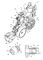
- FIG. 1 is a perspective view of a seeding machine.
- FIG. 2 is a front perspective view of a pneumatic plug.
- FIG. 3 is a rear perspective view of the pneumatic plug.
- FIG. 4 is a cross sectional view of the pneumatic plug mounted to the seeding machine.
- the seeding machine 10 comprises an individual row crop planting unit that is mounted to a transverse toolbar, not shown, by U-bolts that engage a mounting plate 12 .
- the planting unit is provided with a frame 14 that is coupled to the mounting plate 12 by a parallel linkage 16 .
- the parallel linkage 16 allows the planting unit to move up and down to a limited degree relative to the toolbar.
- Seed is automatically directed to the planter by a pneumatic seed on demand delivery system.
- the seed on demand delivery system directs the seed pneumatically from a main hopper, not shown, through seed hose 18 to an auxiliary hopper 20 mounted on fame 14 . Seed in the auxiliary hopper 20 is metered by a pneumatic pressure seed meter 22 and directed to a planting furrow by a seed tube, not shown.
- the planting furrow is formed by a double disc furrow opener 24 having depth gauging wheels 26 .
- the depth of the planting furrow is controlled by the positioning of handle 28 which controls the vertical position of the depth gauging wheels 26 relative to the furrow opener 24 .
- the planting furrow with metered seed deposited therein by the seed tube is closed by closing wheels 30 .
- a forward mounted coulter 32 is used for slicing through crop residue before it encounters the furrow opener 24 .
- the seed meter 22 is driven by a flexible rotatable drive shaft, not shown, that drives gear box 34 .
- the flexible and rotatable drive shaft is of a type manufactured and marketed by Elliott Manufacturing Company, LLC. of Binghamton, N.Y.
- a ground driven transmission, not shown, provides a rotational input into the flexible drive shaft. In this way the ground speed of the seeding machine 10 controls the speed of the seed meter 22 .
- the illustrated seed meter 22 is a vacuum seed meter. That means the seed meter 22 uses negative air pressure to attract seeds to a rotating disc having seed positions defined by circumferentially arranged apertures.
- a pneumatic hose 36 couples the seed meter to a vacuum source.
- the present invention is illustrated as a vacuum seed meter, it can also be used with a positive pressure seed meter.
- the plug 40 of the present invention can be used to close off the vacuum from the deactivated planting unit.
- the plug 40 comprises a rubber body having an annular rim 42 , an insert portion 44 and a sealing wall 46 .
- the annular rim 42 defines an annular cavity 48 which engages the pneumatic inlet 52 of the seed meter 22 .
- the annular rim 42 and the annular cavity 48 defined by the rim are both cylindrical.
- the annular rim 42 is provided with two inwardly projecting sealing ridges 50 for engaging the outer sidewall of the pneumatic inlet 52 .
- the insert portion 44 is cylindrical for insertion into the pneumatic hose 36 .
- the insert portion 44 is provided with two outwardly projecting sealing ridges 54 that engage the inner sidewall of the pneumatic hose 36 .
- the sealing wall 46 pneumatically seals the pneumatic hose 36 .
- the insert portion 44 has a first end adjacent to the annular rim 42 and a second end opposite the first end on which the sealing wall 46 is located.
- an operator lifts the planting unit upward out of contact with the ground and locks it in place.
- the operator then removes the pneumatic hose 36 from the seed meter 22 .
- the insert portion 44 of the plug 40 is inserted into the end of the hose 34 and the annular rim 42 is then mounted over the pneumatic inlet 52 .
- the hose 34 is pneumatically sealed by the sealing wall 46 .
- the hose 34 is also restrained from flopping around and becoming damaged by mounting the annular rim 42 over the pneumatic inlet 52 of the seed meter 22 .
Landscapes
- Life Sciences & Earth Sciences (AREA)
- Soil Sciences (AREA)
- Environmental Sciences (AREA)
- Sowing (AREA)
Abstract
A pneumatic plug is used to seal off a pneumatic pressure source from a pneumatic pressure seed meter. The pneumatic plug comprises an annular rim defining an annular cavity, a insert portion and a sealing wall. The plug is an integral rubber body. The insert portion is inserted into a pneumatic hose supplying pneumatic pressure to the seed meter. The annular rim defines an annular cavity into which the pneumatic inlet of the seed meter is received. The annular cavity is provided with two inwardly extending sealing ridges that engage the outer sidewalls of the pneumatic inlet. The sealing wall provides a pneumatic seal for the pneumatic hose.
Description
The present invention is directed to a pneumatic plug for a pneumatic hose on a seed meter which has an inlet portion that can be mounted to the pneumatic inlet of the seed meter.
Pneumatic seed meters are well known in the art. There are two basic types of pneumatic seed meters, positive air pressure seed meters and vacuum seed meters. Both of these types of pneumatic seed meters have a rotatable disc located in a housing. The rotatable disc is provided with circumferentially spaced apertures defining seed locations. The rotatable disc is rotated through a seed puddle and the individual seeds are attracted to the spaced apertures by the difference in pneumatic pressure on one side of the disc from the other. The individual seeds are then taken up by the disc and rotated to an outlet where the differential pneumatic pressure is removed and the seed is deposited into a seed tube for travel to a planting furrow.
In a positive pressure seed meter the difference in pneumatic pressure is created from a positive pressure source. The seed puddle, in a positive pressure seed meter, is located on the same side of the disc as source of positive pneumatic air pressure. In a vacuum seed meter the difference in pneumatic pressure is created by negative air pressure. The seed puddle, in a vacuum seed meter, is located on the opposite side of the disc from the source of negative pneumatic pressure.
Row crop planters are typically provided with a plurality of planting units. Each of the planting units have a seed meter. Sometimes it is desirable to disable a number of the planting units while still planting. For example every other planting unit may be disabled, so that the row crop planter can plant thirty inch row corn instead of fifteen inch row soybeans. First the planting unit is lifted off the ground and locked in place. With pneumatic pressure seed meters it is also necessary to close off the pneumatic pressure source. One solution is to remove the pneumatic hose supplying pneumatic pressure to the seed meter from a pneumatic manifold. The pneumatic hose opening in the manifold is then closed off with a rubber cap. This operation can prove difficult as the manifold can be difficult to get to. In addition, the pneumatic hose is left free to hang leaving it susceptible to damage.
It is an object of the present invention to provide a pneumatic plug for a pneumatic pressure seed meter that closes off a pneumatic hose and which mounts the closed off hose to the seed meter.
A pneumatic plug is used to seal off a pneumatic pressure source from a pneumatic pressure seed meter. The pneumatic plug comprises an annular rim defining an annular cavity, an insert portion and a sealing wall. The plug is an integral rubber body. The insert portion of the pneumatic plug is inserted into the pneumatic hose supplying pneumatic pressure to the pneumatic pressure seed meter. The insert portion is provided with two outwardly extending sealing ridges that engage the interior sidewalls of the hose. The annular rim of the plug is mounted over the pneumatic inlet of the pneumatic pressure seed meter that was previously covered by the pneumatic hose. The sealing wall is adjacent the insert portion and provides a pneumatic seal for the pneumatic hose.
It is also desirable to make the pneumatic plug in a contrasting color from the seed meter so that the operator can readily ascertain if the pneumatic plug is in place.
The seeding machine 10 comprises an individual row crop planting unit that is mounted to a transverse toolbar, not shown, by U-bolts that engage a mounting plate 12. The planting unit is provided with a frame 14 that is coupled to the mounting plate 12 by a parallel linkage 16. The parallel linkage 16 allows the planting unit to move up and down to a limited degree relative to the toolbar. Seed is automatically directed to the planter by a pneumatic seed on demand delivery system. The seed on demand delivery system directs the seed pneumatically from a main hopper, not shown, through seed hose 18 to an auxiliary hopper 20 mounted on fame 14. Seed in the auxiliary hopper 20 is metered by a pneumatic pressure seed meter 22 and directed to a planting furrow by a seed tube, not shown.
The planting furrow is formed by a double disc furrow opener 24 having depth gauging wheels 26. The depth of the planting furrow is controlled by the positioning of handle 28 which controls the vertical position of the depth gauging wheels 26 relative to the furrow opener 24. The planting furrow with metered seed deposited therein by the seed tube is closed by closing wheels 30. A forward mounted coulter 32 is used for slicing through crop residue before it encounters the furrow opener 24.
The seed meter 22 is driven by a flexible rotatable drive shaft, not shown, that drives gear box 34. The flexible and rotatable drive shaft is of a type manufactured and marketed by Elliott Manufacturing Company, LLC. of Binghamton, N.Y. A ground driven transmission, not shown, provides a rotational input into the flexible drive shaft. In this way the ground speed of the seeding machine 10 controls the speed of the seed meter 22.
The illustrated seed meter 22 is a vacuum seed meter. That means the seed meter 22 uses negative air pressure to attract seeds to a rotating disc having seed positions defined by circumferentially arranged apertures. A pneumatic hose 36 couples the seed meter to a vacuum source. Although the present invention is illustrated as a vacuum seed meter, it can also be used with a positive pressure seed meter.
If it is desirable to deactivate a planting unit while using other planting units on a seeding machine, the plug 40 of the present invention can be used to close off the vacuum from the deactivated planting unit. The plug 40 comprises a rubber body having an annular rim 42, an insert portion 44 and a sealing wall 46. The annular rim 42 defines an annular cavity 48 which engages the pneumatic inlet 52 of the seed meter 22. The annular rim 42 and the annular cavity 48 defined by the rim are both cylindrical. The annular rim 42 is provided with two inwardly projecting sealing ridges 50 for engaging the outer sidewall of the pneumatic inlet 52.
The insert portion 44 is cylindrical for insertion into the pneumatic hose 36. The insert portion 44 is provided with two outwardly projecting sealing ridges 54 that engage the inner sidewall of the pneumatic hose 36.
The sealing wall 46 pneumatically seals the pneumatic hose 36. The insert portion 44 has a first end adjacent to the annular rim 42 and a second end opposite the first end on which the sealing wall 46 is located.
To make a planting unit inactive, an operator lifts the planting unit upward out of contact with the ground and locks it in place. The operator then removes the pneumatic hose 36 from the seed meter 22. The insert portion 44 of the plug 40 is inserted into the end of the hose 34 and the annular rim 42 is then mounted over the pneumatic inlet 52. In this way the hose 34 is pneumatically sealed by the sealing wall 46. The hose 34 is also restrained from flopping around and becoming damaged by mounting the annular rim 42 over the pneumatic inlet 52 of the seed meter 22.
Having described the illustrated embodiment, it will become apparent that various modifications can be made without departing from the scope of the invention as defined in the accompanying claims.
Claims (10)
1. A seeding machine for applying seed to a field, the seeding machine comprising:
a frame;
a furrow opener mounted to the frame for forming a planting furrow;
a pneumatic pressure seed meter mounted to the frame, the pneumatic pressure seed meter using pneumatic pressure to meter seed being directed to a planting furrow;
a pneumatic hose coupled to the pneumatic pressure seed meter, the pneumatic hose being provided with a plug that is attached to and pneumatically seals the pneumatic hose from the pneumatic pressure seed meter, the plug being mounted to the pneumatic pressure seed meter.
2. The seeding machine as defined by claim 1 wherein pneumatic pressure seed meter is provided with a pneumatic inlet and the plug is provided with an annular rim that defines an annular cavity into which the pneumatic inlet is received.
3. The seeding machine as defined by claim 2 wherein the plug is provided with an insert portion which is inserted into the pneumatic hose.
4. The seeding machine as defined by claim 3 wherein the plug is provided with a sealing wall to pneumatically seal the pneumatic hose.
5. The seeding machine as defined by claim 4 wherein the plug is an integral rubber body including the annular rim, the insert portion and the sealing wall.
6. The seeding machine as defined by claim 5 wherein the annular rim and the insert portion are cylindrical.
7. The seeding machine as defined by claim 6 wherein the insert portion has a first end adjacent the annular rim and a second end opposite the first end having the sealing wall.
8. The seeding machine as defined by claim 7 wherein the annular rim is provided with two inwardly extending sealing ridges and the insert portion is provided with two outwardly extending sealing ridges.
9. The seeding machine as defined by claim 6 wherein the pneumatic pressure seed meter is a vacuum seed meter.
10. The seeding machine as defined by claim 1 wherein the pneumatic pressure seed meter is provided with a pneumatic inlet and the plug is provided with an annular rim defining an annular cavity that mounts to the pneumatic inlet, the insert portion having a sealing wall for pneumatically sealing the pneumatic hose, the plug also being provided with an insert portion which is inserted into the pneumatic hose, the insert portion and the annular rim being cylindrical.
Priority Applications (1)
| Application Number | Priority Date | Filing Date | Title |
|---|---|---|---|
| US10/639,407 US7017502B2 (en) | 2003-08-11 | 2003-08-11 | Pneumatic plug for a seed meter |
Applications Claiming Priority (1)
| Application Number | Priority Date | Filing Date | Title |
|---|---|---|---|
| US10/639,407 US7017502B2 (en) | 2003-08-11 | 2003-08-11 | Pneumatic plug for a seed meter |
Publications (2)
| Publication Number | Publication Date |
|---|---|
| US20050034640A1 US20050034640A1 (en) | 2005-02-17 |
| US7017502B2 true US7017502B2 (en) | 2006-03-28 |
Family
ID=34135872
Family Applications (1)
| Application Number | Title | Priority Date | Filing Date |
|---|---|---|---|
| US10/639,407 Expired - Lifetime US7017502B2 (en) | 2003-08-11 | 2003-08-11 | Pneumatic plug for a seed meter |
Country Status (1)
| Country | Link |
|---|---|
| US (1) | US7017502B2 (en) |
Cited By (15)
| Publication number | Priority date | Publication date | Assignee | Title |
|---|---|---|---|---|
| US20080053674A1 (en) * | 2006-08-16 | 2008-03-06 | Michael Frederick | Modified box scraper system and apparatus |
| US7640877B1 (en) | 2008-11-14 | 2010-01-05 | Cnh Canada, Ltd. | Dense phase distribution branch |
| US20100101469A1 (en) * | 2005-04-28 | 2010-04-29 | Donald Keith Landphair | Seed hopper and routing structure for varying material delivery to row units |
| US20100124958A1 (en) * | 2008-11-14 | 2010-05-20 | Russell James Memory | Granular containment assembly and method |
| US20100122646A1 (en) * | 2008-11-14 | 2010-05-20 | Russell James Memory | Agricultural implement with dense phase product dispensing and purging |
| US20100124464A1 (en) * | 2008-11-14 | 2010-05-20 | Russell James Memory | Valve and method for dense phase flow control |
| US7743719B2 (en) | 2008-11-14 | 2010-06-29 | Cnh Canada, Ltd. | Sectional distribution of granular product |
| US7752984B2 (en) | 2008-11-14 | 2010-07-13 | Cnh Canada, Ltd. | Device and method for dense phase transport of seed |
| US7779769B2 (en) | 2008-11-14 | 2010-08-24 | Cnh Canada, Ltd. | Agricultural implement with dense phase product flow from a primary container |
| US7789103B2 (en) | 2008-11-14 | 2010-09-07 | Cnh Canada, Ltd. | Dense phase induction system and method |
| US7798079B2 (en) | 2008-11-14 | 2010-09-21 | Cnh Canada, Ltd. | Pressure supply assembly for an agricultural implement with dense phase product flow |
| US20110098851A1 (en) * | 2009-10-28 | 2011-04-28 | Pioneer Hi-Bred International, Inc. | Automated seed detection and planting synchronization apparatus, method and system |
| EP2854500B1 (en) | 2012-05-31 | 2016-04-27 | Väderstad Holding AB | Agricultural implement and method for feeding granular material |
| US9528643B2 (en) | 2014-12-02 | 2016-12-27 | Cnh Industrial Canada, Ltd. | Air grommet connector |
| US9901023B2 (en) | 2012-05-31 | 2018-02-27 | Vaderstad-Verken Ab | Separator and method of separating granular material in an agricultural implement |
Families Citing this family (2)
| Publication number | Priority date | Publication date | Assignee | Title |
|---|---|---|---|---|
| US7971748B2 (en) * | 2003-09-17 | 2011-07-05 | Mastrad Sa | Flexible mold with grasping handles |
| US7665409B2 (en) * | 2007-07-06 | 2010-02-23 | Cnh America Llc | Planter with structural air manifold |
Citations (2)
| Publication number | Priority date | Publication date | Assignee | Title |
|---|---|---|---|---|
| US20010011464A1 (en) * | 1999-05-28 | 2001-08-09 | Mark Waco | Air conditioning cleaning apparatus, kits & methods |
| DE10307532A1 (en) * | 2003-02-21 | 2004-09-02 | Volkswagen Ag | Connector structure for connecting a vacuum pipe to a motor vehicle's brake booster has a vacuum pipe connector section connected into bushing on the component's side |
-
2003
- 2003-08-11 US US10/639,407 patent/US7017502B2/en not_active Expired - Lifetime
Patent Citations (2)
| Publication number | Priority date | Publication date | Assignee | Title |
|---|---|---|---|---|
| US20010011464A1 (en) * | 1999-05-28 | 2001-08-09 | Mark Waco | Air conditioning cleaning apparatus, kits & methods |
| DE10307532A1 (en) * | 2003-02-21 | 2004-09-02 | Volkswagen Ag | Connector structure for connecting a vacuum pipe to a motor vehicle's brake booster has a vacuum pipe connector section connected into bushing on the component's side |
Non-Patent Citations (3)
| Title |
|---|
| Case International Brochure, "900 Series Early Riser Cycle Air Planters", Front Cover Page, pp. 12 & 13, Received in Patent Department Sep. 26, 1990. |
| John Deere Brochure, "Accuracy Experts", pp. 16 & 21, Front Cover & Back Cover Pages, Published Aug. 1990. |
| John Deere Operator's Manual, "MaxEmerge 2 Split Row Planting Attachment", pp. 6-12, Front Cover & Back Cover Pages, Published 1987. |
Cited By (20)
| Publication number | Priority date | Publication date | Assignee | Title |
|---|---|---|---|---|
| US20100101469A1 (en) * | 2005-04-28 | 2010-04-29 | Donald Keith Landphair | Seed hopper and routing structure for varying material delivery to row units |
| US20080053674A1 (en) * | 2006-08-16 | 2008-03-06 | Michael Frederick | Modified box scraper system and apparatus |
| US7793738B2 (en) * | 2006-08-16 | 2010-09-14 | Michael Frederick | Modified box scraper system and apparatus |
| US20100124464A1 (en) * | 2008-11-14 | 2010-05-20 | Russell James Memory | Valve and method for dense phase flow control |
| US7798079B2 (en) | 2008-11-14 | 2010-09-21 | Cnh Canada, Ltd. | Pressure supply assembly for an agricultural implement with dense phase product flow |
| US20100124958A1 (en) * | 2008-11-14 | 2010-05-20 | Russell James Memory | Granular containment assembly and method |
| US7743719B2 (en) | 2008-11-14 | 2010-06-29 | Cnh Canada, Ltd. | Sectional distribution of granular product |
| US7752984B2 (en) | 2008-11-14 | 2010-07-13 | Cnh Canada, Ltd. | Device and method for dense phase transport of seed |
| US7779769B2 (en) | 2008-11-14 | 2010-08-24 | Cnh Canada, Ltd. | Agricultural implement with dense phase product flow from a primary container |
| US7789103B2 (en) | 2008-11-14 | 2010-09-07 | Cnh Canada, Ltd. | Dense phase induction system and method |
| US7640877B1 (en) | 2008-11-14 | 2010-01-05 | Cnh Canada, Ltd. | Dense phase distribution branch |
| US7798078B2 (en) | 2008-11-14 | 2010-09-21 | Cnh Canada, Ltd. | Granular containment assembly and method |
| US20100122646A1 (en) * | 2008-11-14 | 2010-05-20 | Russell James Memory | Agricultural implement with dense phase product dispensing and purging |
| US7806061B2 (en) | 2008-11-14 | 2010-10-05 | Cnh Canada, Ltd. | Agricultural implement with dense phase product dispensing and purging |
| US8342373B2 (en) | 2008-11-14 | 2013-01-01 | Cnh Canada, Ltd. | Valve and method for dense phase flow control |
| US7938075B1 (en) | 2009-10-28 | 2011-05-10 | Pioneer Hi-Bred International, Inc. | Automated seed detection and planting synchronization apparatus, method and system |
| US20110098851A1 (en) * | 2009-10-28 | 2011-04-28 | Pioneer Hi-Bred International, Inc. | Automated seed detection and planting synchronization apparatus, method and system |
| EP2854500B1 (en) | 2012-05-31 | 2016-04-27 | Väderstad Holding AB | Agricultural implement and method for feeding granular material |
| US9901023B2 (en) | 2012-05-31 | 2018-02-27 | Vaderstad-Verken Ab | Separator and method of separating granular material in an agricultural implement |
| US9528643B2 (en) | 2014-12-02 | 2016-12-27 | Cnh Industrial Canada, Ltd. | Air grommet connector |
Also Published As
| Publication number | Publication date |
|---|---|
| US20050034640A1 (en) | 2005-02-17 |
Similar Documents
| Publication | Publication Date | Title |
|---|---|---|
| US7017502B2 (en) | Pneumatic plug for a seed meter | |
| CA2987213C (en) | Multiple seed type seed meter with seed switching mechanism | |
| US10368478B2 (en) | Multiple variety seed meter with segmented sump arrangement and seed switching arrangement | |
| CA2991456C (en) | Pre-metering system for feeding different types of seed into a seed meter | |
| US11432459B2 (en) | Dual-disk seed meter for multi-variety seed planting | |
| US7472660B2 (en) | Seed tube for an agricultural seeding machine | |
| US20100224110A1 (en) | Seed Meter And Seed Disk With Peripheral Edge Seed Pick-Up | |
| CA3042624A1 (en) | Individual row vacuum system | |
| US6142086A (en) | Air seeder singulation system | |
| US20200008343A1 (en) | Radial suction-type seed metering apparatus | |
| UA82863C2 (en) | Arrangement for opening and closing sowing furrow in the ground and agricultural machine, containing such arrangement | |
| WO2015168198A1 (en) | Dual corn and soybean seed disc | |
| US8733258B2 (en) | Seed flap for seed meter | |
| CN111083969A (en) | Single-seed high-precision seeder | |
| SE2150191A1 (en) | Singulating device, agricultural implement and method for distributing granular material to soil | |
| US20170086357A1 (en) | Seed planting and metering equipment | |
| CN201830638U (en) | Walking tractor type special small air-suction corn seeding device | |
| CN201430766Y (en) | Air-aspiration type precision combined peanut seeder | |
| CN211721072U (en) | Single-seed high-precision seeder | |
| CN221329539U (en) | Miss-seeding monitoring and reseeding integrated air suction type precise seed metering device | |
| CN109716899B (en) | Rape seeder | |
| KR20200099220A (en) | Seeding machine of seed | |
| CN202197521U (en) | Air-aspiration type peanut precision planter |
Legal Events
| Date | Code | Title | Description |
|---|---|---|---|
| AS | Assignment |
Owner name: DEERE & COMPANY, ILLINOIS Free format text: ASSIGNMENT OF ASSIGNORS INTEREST;ASSIGNORS:QUAM, DALE ALAN;MCCARTNEY, SCOTT CHARLES;REEL/FRAME:014745/0356 Effective date: 20030904 |
|
| STCF | Information on status: patent grant |
Free format text: PATENTED CASE |
|
| FPAY | Fee payment |
Year of fee payment: 4 |
|
| FPAY | Fee payment |
Year of fee payment: 8 |
|
| MAFP | Maintenance fee payment |
Free format text: PAYMENT OF MAINTENANCE FEE, 12TH YEAR, LARGE ENTITY (ORIGINAL EVENT CODE: M1553) Year of fee payment: 12 |