US7012767B2 - Optical pickup lens, molded optical component, handling method, and mold for optical component - Google Patents
Optical pickup lens, molded optical component, handling method, and mold for optical component Download PDFInfo
- Publication number
- US7012767B2 US7012767B2 US10/774,615 US77461504A US7012767B2 US 7012767 B2 US7012767 B2 US 7012767B2 US 77461504 A US77461504 A US 77461504A US 7012767 B2 US7012767 B2 US 7012767B2
- Authority
- US
- United States
- Prior art keywords
- section
- item
- lens
- objective lens
- optical
- Prior art date
- Legal status (The legal status is an assumption and is not a legal conclusion. Google has not performed a legal analysis and makes no representation as to the accuracy of the status listed.)
- Expired - Fee Related, expires
Links
Images


Classifications
-
- C—CHEMISTRY; METALLURGY
- C03—GLASS; MINERAL OR SLAG WOOL
- C03B—MANUFACTURE, SHAPING, OR SUPPLEMENTARY PROCESSES
- C03B11/00—Pressing molten glass or performed glass reheated to equivalent low viscosity without blowing
- C03B11/06—Construction of plunger or mould
- C03B11/08—Construction of plunger or mould for making solid articles, e.g. lenses
-
- B—PERFORMING OPERATIONS; TRANSPORTING
- B29—WORKING OF PLASTICS; WORKING OF SUBSTANCES IN A PLASTIC STATE IN GENERAL
- B29C—SHAPING OR JOINING OF PLASTICS; SHAPING OF MATERIAL IN A PLASTIC STATE, NOT OTHERWISE PROVIDED FOR; AFTER-TREATMENT OF THE SHAPED PRODUCTS, e.g. REPAIRING
- B29C45/00—Injection moulding, i.e. forcing the required volume of moulding material through a nozzle into a closed mould; Apparatus therefor
- B29C45/17—Component parts, details or accessories; Auxiliary operations
- B29C45/26—Moulds
- B29C45/27—Sprue channels ; Runner channels or runner nozzles
-
- B—PERFORMING OPERATIONS; TRANSPORTING
- B29—WORKING OF PLASTICS; WORKING OF SUBSTANCES IN A PLASTIC STATE IN GENERAL
- B29D—PRODUCING PARTICULAR ARTICLES FROM PLASTICS OR FROM SUBSTANCES IN A PLASTIC STATE
- B29D11/00—Producing optical elements, e.g. lenses or prisms
- B29D11/00009—Production of simple or compound lenses
- B29D11/00432—Auxiliary operations, e.g. machines for filling the moulds
-
- G—PHYSICS
- G02—OPTICS
- G02B—OPTICAL ELEMENTS, SYSTEMS OR APPARATUS
- G02B3/00—Simple or compound lenses
- G02B3/02—Simple or compound lenses with non-spherical faces
- G02B3/04—Simple or compound lenses with non-spherical faces with continuous faces that are rotationally symmetrical but deviate from a true sphere, e.g. so called "aspheric" lenses
-
- G—PHYSICS
- G11—INFORMATION STORAGE
- G11B—INFORMATION STORAGE BASED ON RELATIVE MOVEMENT BETWEEN RECORD CARRIER AND TRANSDUCER
- G11B7/00—Recording or reproducing by optical means, e.g. recording using a thermal beam of optical radiation by modifying optical properties or the physical structure, reproducing using an optical beam at lower power by sensing optical properties; Record carriers therefor
- G11B7/12—Heads, e.g. forming of the optical beam spot or modulation of the optical beam
- G11B7/135—Means for guiding the beam from the source to the record carrier or from the record carrier to the detector
- G11B7/1372—Lenses
- G11B7/1374—Objective lenses
-
- B—PERFORMING OPERATIONS; TRANSPORTING
- B29—WORKING OF PLASTICS; WORKING OF SUBSTANCES IN A PLASTIC STATE IN GENERAL
- B29L—INDEXING SCHEME ASSOCIATED WITH SUBCLASS B29C, RELATING TO PARTICULAR ARTICLES
- B29L2011/00—Optical elements, e.g. lenses, prisms
- B29L2011/0016—Lenses
-
- C—CHEMISTRY; METALLURGY
- C03—GLASS; MINERAL OR SLAG WOOL
- C03B—MANUFACTURE, SHAPING, OR SUPPLEMENTARY PROCESSES
- C03B2215/00—Press-moulding glass
- C03B2215/40—Product characteristics
- C03B2215/404—Products with identification marks
-
- C—CHEMISTRY; METALLURGY
- C03—GLASS; MINERAL OR SLAG WOOL
- C03B—MANUFACTURE, SHAPING, OR SUPPLEMENTARY PROCESSES
- C03B2215/00—Press-moulding glass
- C03B2215/40—Product characteristics
- C03B2215/46—Lenses, e.g. bi-convex
- C03B2215/49—Complex forms not covered by groups C03B2215/47 or C03B2215/48
-
- G—PHYSICS
- G11—INFORMATION STORAGE
- G11B—INFORMATION STORAGE BASED ON RELATIVE MOVEMENT BETWEEN RECORD CARRIER AND TRANSDUCER
- G11B7/00—Recording or reproducing by optical means, e.g. recording using a thermal beam of optical radiation by modifying optical properties or the physical structure, reproducing using an optical beam at lower power by sensing optical properties; Record carriers therefor
- G11B7/12—Heads, e.g. forming of the optical beam spot or modulation of the optical beam
- G11B7/22—Apparatus or processes for the manufacture of optical heads, e.g. assembly
-
- Y—GENERAL TAGGING OF NEW TECHNOLOGICAL DEVELOPMENTS; GENERAL TAGGING OF CROSS-SECTIONAL TECHNOLOGIES SPANNING OVER SEVERAL SECTIONS OF THE IPC; TECHNICAL SUBJECTS COVERED BY FORMER USPC CROSS-REFERENCE ART COLLECTIONS [XRACs] AND DIGESTS
- Y02—TECHNOLOGIES OR APPLICATIONS FOR MITIGATION OR ADAPTATION AGAINST CLIMATE CHANGE
- Y02P—CLIMATE CHANGE MITIGATION TECHNOLOGIES IN THE PRODUCTION OR PROCESSING OF GOODS
- Y02P40/00—Technologies relating to the processing of minerals
- Y02P40/50—Glass production, e.g. reusing waste heat during processing or shaping
- Y02P40/57—Improving the yield, e-g- reduction of reject rates
Definitions
- the present invention relates to a pickup lens for an optical disk which is used for reading information from a storage medium, or recording, mainly by using a laser beam, and in particular, to a pickup lens for an extremely small optical disk.
- the optical disks mentioned above have started from the music CD, and therefore, it is always necessary for the DVD which is becoming a leading recording medium now to consider interchangeability with CD, and a size of the DVD is large, which makes it difficult to provide a small-sized equipment, resulting in a problem.
- a small-sized medium in a size of 8 cm and a deformed medium having a size of a business card have made an appearance, but it is unavoidable that they have less capacity.
- the DVD has a problem that many standards concerning information recording are present and interchangeability between them is insufficient.
- an optical pickup lens and a unit are required to be small in size.
- An object of the invention is to propose forms which make manufacturing, assembling and adjustment to be easy for an optical pickup lens and an optical pickup unit which are extremely small.
- An objective lens used in an optical pickup device that conducts recording and/or reproduction of information for an optical information recording medium
- the objective lens according to Item (1—1) wherein two connecting sections are provided to be extended from the lens section in the direction to face each other.
- the objective lens according to Item (1—1) wherein a lens section is formed to be arranged at the center of a rectangular connecting section.
- An optical molded component having therein a supporting shaft section having a first cross-sectional area, a connecting section that is provided to be continued in the axial direction of the supporting shaft section and has a cross-sectional area smaller than the first cross-sectional area and an optical functional section provided to be continued from the connecting section, wherein the total weight of the supporting shaft section and the connecting section is greater than the weight of the optical functional section.
- An optical molded component having therein a supporting shaft section having a first cross-sectional area, a connecting section that is provided to be continued in the axial direction of the supporting shaft section and has a cross-sectional area smaller than the first cross-sectional area and an optical functional section provided to be continued from the connecting section, wherein the total weight of the supporting shaft section and the connecting section is not less than 70% of the whole weight.
- An optical molded component having therein a supporting shaft section having a first cross-sectional area, a connecting section that is provided to be continued in the axial direction of the supporting shaft section and has a cross-sectional area smaller than the first cross-sectional area and an optical functional section provided to be continued from the connecting section, wherein an information recording site is provided on the supporting shaft section.
- An optical molded component having therein a supporting shaft section having a first cross-sectional area, a connecting section that is provided to be continued in the axial direction of the supporting shaft section and has a cross-sectional area smaller than the first cross-sectional area and an optical functional section provided to be continued from the connecting section, wherein an information recording site is provided on the connecting section.
- a side section of the protruded portion is composed of a pair of longitudinal sides which face each other in the longitudinal direction of the supporting section and a pair of lateral sides which face each other in the lateral direction, and an angle formed between the longitudinal side and the parallel flat section is made to be 45° or less, in the optical molded component described in Item (2-9).
- the protruded portion is formed to be almost in a truncated square pyramid, in the optical molded component described in Item (2-12).
- the connecting section has an index portion that is based on a distance from the center of an optical axis of the optical functional section, in the optical molded component described in either one of Items (2-1)–(2-18).
- the index portion is formed by cutting into the connecting section, in the optical molded component described in Item (2-19).
- the index portion is formed to be protruded from the connecting section, in the optical molded component described in Item (2-19).
- the index portion is formed to be a straight line extending in the lateral direction of the connecting section, in the optical molded component described in either one of Items (2-19)–(2-21).
- the index portion is formed to be a locus of a circle having a prescribed radius whose center is on the optical axis in the optical molded component described in either one of Items (2-19)–(2-21).
- a method of handling an molded optical component is characterized in that an optical molded component is taken out of a metal mold for molding an optical molded component that is provided with a first resin inflow path having a first cross-sectional area, a second resin inflow path being located ahead of the first resin inflow path in the direction of resin flow and having a cross-sectional area smaller than the first cross-sectional area and an optical functional section molding section being located further ahead of the second resin inflow path in the direction of resin flow, and then, the optical molded component is handled on the basis of a site formed by the first resin inflow path.
- a method of handling an molded optical component is characterized in that an optical molded component is taken out of a metal mold for molding an optical molded component that is provided with a first resin inflow path having a first cross-sectional area, a second resin inflow path being located ahead of the first resin inflow path in the direction of resin flow and having a cross-sectional area smaller than the first cross-sectional area and an optical functional section molding section being located further ahead of the second resin inflow path in the direction of resin flow, and then, the optical molded component is handled on the basis of a site which is formed by the first resin inflow path and is continued to a site formed by the second resin inflow path, after the site formed by the first resin inflow path is cut.
- a method of handling an molded optical component is characterized in that an optical molded component is taken out of a metal mold for molding an optical molded component that is provided with a first resin inflow path having a first cross-sectional area, a second resin inflow path being located ahead of the first resin inflow path in the direction of resin flow and having a cross-sectional area smaller than the first cross-sectional area and an optical functional section molding section being located further ahead of the second resin inflow path in the direction of resin flow, and then, the optical molded component is handled on the basis of a site which is formed by the first resin inflow path and is continued to a site formed by the second resin inflow path, after the prescribed site formed by the first resin inflow path is cut.
- the “handling” is to record information on a portion formed by the second resin inflow path in the optical molded component, in the method of handling an optical molded component described in either one of Item (2-24)–(2-34).
- the invention of the handling method relating to the molded component among the present inventions can be attained by the following means.
- the invention relating to the method of molding employing a metal mold among the present inventions can be attained by the following means.
- An optical molded component that is molded by the metal mold for molding an optical molded component in the aforesaid Items (2-44)–(2-57), and has a supporting shaft section formed by the first resin inflow path, a connecting section formed by the second resin inflow path and the optical functional section formed by the optical functional section molding section.
- the invention relating to the method of molding employing a metal mold among the present inventions can be attained by the following means.
- the invention relating to a method of assembling an optical pickup unit among the present inventions can be attained by the following means.
- FIG. 1 is a diagram of an objective lens relating to Example 1 that is viewed in the direction of an optical axis.
- FIG. 2 is a diagram of the objective lens shown in FIG. 1 that is viewed in the direction shown with “a”.
- FIG. 3 is a diagram of an objective lens relating to Example 2 that is viewed in the direction of an optical axis.
- FIG. 4 is a diagram of the objective lens shown in FIG. 3 that is viewed in the direction shown with “a”.
- FIG. 5 is an example of an objective lens relating to Example 2.
- FIG. 6 is an example of an objective lens relating to Example 2.
- FIG. 7 is an example of an objective lens relating to Example 2.
- FIG. 8 is a diagram of an objective lens relating to Example 3 that is viewed in the direction of an optical axis.
- FIG. 9 is a diagram of the objective lens shown in FIG. 8 that is viewed in the direction shown with “a”.
- FIG. 10 shows a schematic view of the metal mold relating to the invention.
- FIG. 11 is an enlarged drawing of primary portions of the metal mold relating to the invention.
- FIG. 12 is a perspective view of the molded component relating to the invention.
- FIGS. 13( a ) to 13 ( g ) each is a sectional view of the molded component relating to the invention.
- FIG. 14 is a perspective view in the state where information is given to the supporting shaft section of the molded component relating to the invention.
- FIGS. 15( a ) to 15 ( d ) each is a sectional view of an example wherein a three-dimensional distinguishing mark is provided on the supporting shaft portion of the molded component relating to the invention.
- FIGS. 16( a ) to 16 ( g ) each is a perspective view of an example wherein a three-dimensional distinguishing mark is provided on the supporting shaft portion of the molded component relating to the invention.
- FIG. 17 is a sectional view of a metal mold wherein a three-dimensional distinguishing mark is provided on the supporting shaft portion of the molded component relating to the invention.
- FIGS. 18( a ) to 18 ( d ) each is an enlarged drawing of primary portions of the example wherein a stress-concentration portion is provided on the connecting section of the molded component relating to the invention.
- FIGS. 19( a ) and 19 ( b ) each is a perspective view of an example wherein an information recording site is provided on the supporting shaft portion of the molded component relating to the invention.
- FIGS. 20( a ) and 20 ( b ) each is a perspective view of an example of the molded component relating to the invention.
- FIGS. 21( a ) and 21 ( b ) each is a perspective view of an example of the molded component relating to the invention.
- FIG. 22 is a sectional view explaining the separation of an optical molded component from a mold.
- FIG. 1 is a diagram showing objective lens 1 in Example 1 viewed in the optical axis direction
- FIG. 2 is a sectional view showing the same objective lens viewed in the direction shown by the arrow (X).
- the objective lens 1 is an objective lens made of plastic obtained by injection-molding resins filled in a metal mold.
- Lens section 10 is composed of lens (optical functional surface) 11 having an optical function and of a flange section provided to surround the lens 11 , and diameter A of the lens section 10 is 1.3 mm, while, the width of connecting section 20 is 1.2 mm.
- B is equal to 0.92A, while, the conditions in Item (1—1) are satisfied, and the shape in Item (1-2) is kept.
- a connecting section is provided for handling and for supporting the lens section, which is a merit. That is, the connecting section is used as a supporting section for the lens section. It is further possible to give a product name, a lot number and a metal mold number by conducting some printing and marking or other on the connecting section.
- the plastic lens which is injection-molded as stated above employs technologies in Item (1-18) and Item (1-19). Therefore, it is possible to manufacture a large number of lenses in the same shape stably and at high speed.
- the plastic lens has an advantage that inflow of resins and moldability are excellent because dimensional conditions stipulated in Item (1—1) are satisfied.
- a shape of the metal mold is formed so that resins may flow in from connecting section 20 , and technologies in Item (1-3) and Item (1-18) are employed. Due to this, the shape and structure of the metal mold are not complicated, and a resin inflow path can be used as a constitutional component.
- the lens section 10 is arranged so that it may be positioned when its flange section comes in contact with an unillustrated component on the part of a pickup device when the lens section 10 is incorporated in the pickup device, and NA is further stipulated as occasion demands on the optical functional surface of lens surface 11 .
- the optical functional surface thereof is formed to be in a shape of an aspheric surface.
- a diffractive structure is formed on the optical functional surface to be in a form of ring shaped zones by the use of technologies of Item (1-22).
- the diffracting surface may be provided either on the whole optical functional surface or on the desired locations at need. It is further possible to provide the diffracting surface not only for the temperature compensation but also for improvement of optical characteristics and for optical characteristics to be given, including correction of various aberrations.
- optical functions may also be attained by a refracting interface only without providing the diffracting surface.
- the total length C including a lens section and a width section (connecting section or projecting section) is 3 mm
- maximum thickness D (axial thickness in this case) of the lens section is 0.41 mm
- thickness E of the connecting section (projecting section) is 0.2 mm in the foregoing, these figures may further be selected suitably to be preferable.
- connecting section (projecting section) thickness E (mm) satisfies the following formulas. 0.05 ⁇ E ⁇ 0.5 E ⁇ D/2
- a ratio of total length C including a lens section and a connecting section to the lens section A satisfies the following formula. 1.1 ⁇ C/A ⁇ 4.0
- a lens with a general view shown in FIG. 1 wherein a diameter of a lens section and a width of a connecting section are made to be different in terms of dimension was prepared to be studied.
- a size of the lens section first, when the size was smaller than that stipulated in the invention, insufficient quantity of light was caused, and sufficient optical efficiency was not attained. In addition, handling properties were lowered and assembling properties were worsened. Further, inflow of resins in the metal mold was worsened, and a yield for injection molding was lowered.
- the lens When the size was greater than that stipulated in the invention, on the contrary, the lens was closer to an objective lens for CD or DVD available presently on the market, and it was difficult to downsize a recording medium and a pickup device, although optical characteristics were able to be attained.
- the size of the connecting section was smaller than that stipulated in the invention, the resin inflow path was narrowed and resins did not flow in sufficiently, making injection molding itself to be impossible.
- the connecting section was greater than that stipulated in the invention, on the contrary, a shrinkage cavity (defectively molded portion to which no resins flowed in) was caused on the connecting section, which also made it impossible to conduct excellent injection molding.
- the objective lens that was made to be within a range stipulated by the invention proved to be excellent in terms of moldability and handling property and to be of no problem in optical efficiency after the objective lens was incorporated in a pickup device.
- FIG. 3 A general view shown in FIG. 3 represents a diagram of objective lens 2 made of plastic in Example 2 that is viewed in the direction of the optical axis
- FIG. 4 is a sectional view of the same objective lens viewed in the direction shown by the arrow (a), in which the technology of Item (1-4) is employed.
- Example 1 A point of difference between Example 1 and Example 2 is that second connecting section 21 is further provided in Example 2, and other points are the same as those in Example 1. Therefore, the same symbols are given to the same structure, and explanation therefore will be omitted.
- At least one of 20 and 21 serves also as a resin inflow path as mentioned in Item (1-3) or Item (1-18), or possible that each of them serves also as a resin inflow path as mentioned in Item (1-11) and Item (1-12).
- both of the connecting sections are resin inflow paths, it is possible to form at high speed and surely because resins flow in at high speed, and to prevent occurrence of a shrinkage cavity. Further, the time required for injection molding can be reduced, and a cycle time is shortened, improving production efficiency.
- connecting section 20 is different from that of connecting section 21 .
- thicknesses of the connecting sections are made respectively to be 0.1 mm and 0.2 mm.
- lengths of the connecting sections are made respectively to be 0.65 mm and 1.3 mm.
- widths of the connecting sections are made respectively to be 0.8 mm and 1.2 mm. Incidentally, they correspond respectively to 0.92A and 0.62A, and they satisfy the condition of Item (1—1).
- each resin inflow speed for each resin inflow port is different from others, when injection conditions including a melting temperature of resins are taken into consideration. Therefore, it is preferable that the time to start injecting resins is staggered, for controlling the meeting timing (meeting position) for both resins.
- FIG. 8 A general view shown in FIG. 8 represents a diagram of objective lens 2 in Example 3 that is viewed in the direction of the optical axis
- FIG. 9 is a sectional view of the same objective lens viewed in the direction shown by the arrow (a), in which the technology of Item (1-14) is employed.
- a lens section is provided in the form of a floating island at the center of the connecting section extending in a form of a square as a rectangular shape.
- the shape thereof is different from those of Examples 1 and 2, and dimensions of the connecting section are also determined based on the conditions in Item (1—1). Accordingly, there is no problem of injection molding. Since connecting sections are extending in almost all directions from the lens section, handling is more easy, and an area for data marking and printing is increased, which is an advantage. Further, when the connecting section is made to hit, it is easy to position both in x direction and y direction on the plane that is perpendicular to the optical axis, which is an advantage.
- a lens section is 0.85 mm, and a length of one side of the rectangular connecting section in the form of a square is 1.3 mm (1.53A), which satisfy the conditions in Item (1—1).
- a plastic lens is used in the same way as in Examples 1 and 2, a glass mold lens made through compression molding may also be used.
- the shape is suitable for compression molding, because of the shape wherein connecting sections are extending from the whole circumference of the lens section.
- the connecting section is in a shape of a square in the example shown in FIG. 8 , but it is also possible to chamfer or to round the corner of the connecting section at need. If the extent of chamfering is made to be different depending on each corner, this may be utilized for adjusting the lens direction. Even when the rectangle is changed, as occasion demands, to a shape of a rectangle, a shape of a trapezoid, a shape of a parallelogram and a five-or-more-cornered rectangular shape, these shapes are naturally within a scope of the invention.
- an objective lens in the case of an asymmetric shape, an objective lens can be positioned easily and the direction of the objective lens can be determined easily.
- resins are also made to flow in through a part of the connecting section, and in this case, two or more inflow ports may be provided without sticking to one inflow port, as occasion demands, and it is also possible to change a thickness of the connecting section depending on its location.
- An objective lens in Example 4 is exactly the same in terms of shape as those in FIGS. 1–9 , and it is a glass lens obtained by heating a glass pre-form representing a material and then by compression-molding, in which technologies in Items (1-17) and (1-21) are used.
- this is a glass lens, it is excellent in optical characteristics, and it is excellent also in temperature characteristics compared with a plastic lens.
- the pre-form is subjected to compression molding so that a lens section may have sufficient optical functions and a connecting section may be formed. If the width of the connecting section is out of the range of Item (1—1), there is caused a problem that no connecting section is formed, or molding troubles are generated in a lens section in an extreme occasion.
- the inventions in Items (1—1) and (1-2) offer an advantage that handling and incorporating in a pickup device are easy. An advantage that inflow of resins and moldability are excellent is also offered. Even in the case of compression molding, an excellent lens is obtained if this condition is satisfied.
- the shape and structure of the metal mold are not complicated, and a resin inflow path can be used as a constitutional component.
- each individual lens is cut to be in a circular shape, and it can be subjected to rotary adjustment, and can be mounted easily.
- connecting sections are extending in almost all directions from the lens section, handling is more easy, and an area for data marking and printing is increased, which is an advantage. Further, when the connecting section is made to hit, it is easy to position both in x direction and y direction on the plane that is perpendicular to the optical axis, which is an advantage.
- a weld is located outside an optical functional surface, which makes it possible to obtain a lens having excellent optical characteristics.
- Item (1-18) it is possible to manufacture a large number of lenses in the same shape stably and at high speed. Since the dimensional conditions stipulated in Item (1—1) are satisfied, in particular, inflow of resins and moldability are excellent, which is an advantage.
- the shape and structure of the metal mold are not complicated, and a resin inflow path can be used as a constitutional component.
- Item (1-20) it is possible to manufacture a large number of lenses in the same shape stably and at high speed. Since the dimensional conditions stipulated in Item (1—1) are satisfied, in particular, inflow of resins and moldability are excellent, which is an advantage.
- the characteristic of the invention is to form integrally a optical molded component P which is greater in terms of volume and weight than the lens that is incorporated finally in the optical pickup unit, in advance, then, to handle the molded component in the handling process by holding its portion other than the lens as a reference position, and to cut the portion other than the lens after incorporating the molded component in the optical pickup unit or in the containing cartridge.
- the symbol 0 shown in FIG. 10 represents a schematic view of a part of a metal mold M that is used for molding an optical molded component P relating to the invention.
- the metal mold has a resin inflow path which is mostly H-shaped, and it is the so-called multi-cavity metal mold (8-cavity, in this case) wherein melted plastic resin flows in the large diameter path section located at the center, in the direction perpendicular to the page, and 8 pieces of optical molded components in total are formed in a single metal mold.
- the metal mold is composed of a fixed side and a movable side, and these sides are closed when resin flows in, and are parted to open the inside of the metal mold when the resin is cooled after flowing in and molding is completed, so that the molded component may be taken out.
- FIG. 11 is a sectional view of a certain molding site (including the fixed side and movable side) that is viewed in the direction 1 in the metal mold.
- the numeral 31 represents a runner that is the first resin inflow path
- 32 represents a gate that is the second resin inflow path
- 33 represents an optical functional section molding section.
- a section of the first resin inflow path is circular and a section of the second resin inflow path is rectangular.
- an inner surface of the metal mold namely, the molding surface has surface finish conducted by any of various types of processing methods.
- the optical functional section molding section in particular, can be structured so that not only an aspheric surface but also diffractive ring-shaped zones, phase-shifted ring-shaped zones and optical path difference provided ring-shaped zones may be formed, and in that case, a cutting tool having an extremely sharp edge is used to machine the metal mold.
- a material for the metal mold appropriate materials including plated iron can be selected.
- a section of the first resin inflow path (runner) is circular and has a uniform diameter in the drawing, a diameter and a shape of this runner section do not always need to be uniform.
- a diameter for example, may either be changed from 6 to 4 discontinuously or be changed from 6 to 4 continuously to become a tapered shape.
- a shape of a section may suffer a change such as a change from a circle to a rectangle.
- the melted resin flows in the second resin inflow path 32 from the first resin inflow path 31 , and further flows in the optical functional section molding section 33 through the second resin inflow path 32 , and is cooled, thus, molding is completed and the metal mold is opened.
- the inflow direction of the resin is linear for both the first resin inflow path and the second resin inflow path, and both directions agree with each other.
- the aforementioned structure may be changed to comply with the total structure of the metal mold and with other circumstances.
- a metal mold takes a three-dimensional shape, resulting in an advantage that the number of cavities is increased.
- a shape of the molded component that is molded by the use of the metal mold mentioned above is one shown in FIG. 20 .
- An optical molded component P formed by metal mold M shown in FIG. 10 is formed to be in a shape shown in FIG. 10 .
- a diameter of supporting shaft section 41 is 5 mm
- a shape of a section of connecting section 42 is a rectangle whose one side is 0.5–1 mm and a diameter of optical functional section 43 is 1 mm–1.5 mm.
- the supporting shaft section 1 is handled as a reference for various operations, including holding (grasping) and conveyance in the case of taking out the molded component by opening the metal mold, holding (grasping), conveyance, positioning and attaching (or incorporating or assembling) to another member after taking out, and holding (grasping) for cutting.
- the molded component formed by the metal mold 0 is cut at the position shown by AA′ in FIG. 11 .
- Shape P of the optical molded component that has been cut at the position AA′ is shown in FIG. 12 .
- the numeral 41 represents a supporting shaft section formed by the first resin inflow path 31 (runner), 42 represents a connecting section (or a cross linkage section) formed by the second resin inflow path 32 (gate) and 43 represents an optical functional section formed by the optical functional section molding section 33 .
- the optical functional section 43 which is extremely small as stated above and is difficult to be handled individually. Therefore, it is conveyed under the condition of molded component P wherein it is united solidly with supporting shaft section 41 and connecting section 42 , and it is cut at the position of the connecting section 42 immediately before it is incorporated in the optical pickup unit finally or after being incorporated, so that the optical functional section 43 may be mounted on the optical pickup unit. It is further possible for the connecting section 42 to be cut after the molded component P has been housed in a cartridge for conveyance.
- supporting shaft section 41 optical functional section 43
- the supporting shaft section 41 and the connecting section 42 are naturally greater in terms of weight than the optical functional section 3 in the molded component P, for conducting various types of handling stated above.
- the total weight of supporting shaft section 41 and connecting section 42 is not less than 70% of the whole weight.
- an optical molded component mentioned in Item (2-35) is one like molded component P in the state including a supporting shaft section, a connecting section and an optical functional section in FIG. 12 , for example, and it is not one showing the state of molding after the fixed section and the movable section are parted after completion of the molding in the metal mold shown in FIG. 10 .
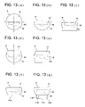
- FIG. 13 shows variations of sectional shapes for the first resin inflow path 31 (runner) shape.
- FIG. 13( a ) shows a circle
- FIG. 13( b ) shows a semicircle
- FIG. 13( c ) shows a trapezoid that is symmetrical laterally.
- an asymmetric shape like FIG. 13( b ) or FIG. 13( c ) is used, it is possible to prevent that supporting shaft section 41 rolls down when it is placed on the stand. Further, in the case of registering, the shape itself serves as an index, which is an advantage.
- FIG. 13( d ) and FIG. 13( e ) It is further possible to employ the shapes of FIG. 13( d ) and FIG. 13( e ), taking handling property, moldability and stiffness of the finished molded component into consideration as other factors.
- FIG. 13( d ) shows a shape of a section in which a rectangular portion (a trapezoid portion that is symmetric laterally) is provided on a chord of the semicircle. Due to this shape, stiffness is enhanced, rotation can be prevented and positioning can be conducted easily.
- FIG. 13( e ) shows a shape of a section in which a plurality of trapezoids each being symmetric laterally are combined. Due to this shape, stiffness is enhanced, rotation can be prevented and positioning can be conducted easily.
- Optical molded component P shown in FIG. 13( f ) is one wherein parallel flat portion 41 a that is almost in parallel with a chord section is formed on a part of an arc section of supporting section 1 . Prevention of its rotation is possible, and positioning thereof is easy. Further, by making this parallel flat portion 41 a to be a fixed side of metal mold M, and by making the chord section to be a movable side of the metal mold M, the optical molded component P can be removed easily from the fixed side after molding by the metal mold M. Due to this, deformation of supporting section 1 caused in the course of removing can be controlled, and excellent optical molded component P can be obtained.
- protruded portion 41 b in a shape which is almost truncated square pyramid (so-called tapered shape) on the parallel flat section 41 a , as shown in FIG. 13( g ) and FIG. 21( a ).
- This protruded portion 41 b has a pair of longitudinal sides 41 c which face each other in the longitudinal direction of the supporting section 41 and a pair of lateral sides 41 d which face each other in the lateral direction.
- the corner section of the protruded portion 41 b is chamfered to make the removing from the metal mold M to be excellent.
- protruded portion 41 b may also be formed to be in a shape of a rectangular parallelepiped without being in a shape of almost truncated square pyramid, as shown in FIG. 21( b ).
- angle ⁇ formed between parallel flat portion 41 a and longitudinal side 41 c is not more than an angle which creates a tangent line of the circle whose center is at O and whose radius is (L 2 +T 2 ) 1/2 , when L represents a length of a pedestal portion of the protruded portion 41 b in the longitudinal direction and T represents a length of protruded portion of 41 b in the direction of its height.
- the angle ⁇ is made to be 45° or less, the moment generated in the supporting shaft portion 41 is reduced, and releasability is improved greatly.
- the smaller the angle ⁇ is the more the releasability is improved.
- the releasability is further improved if the joint section between the longitudinal side 41 b and the parallel flat portion 41 a is made to have a radius of curvature that makes a gentle curve.
- shapes of FIGS. 13( a )– 13 ( g ) can also be applied, without being limited to the shape of FIG. 13( b ). Namely, in the case of a trapezoidal shape that is symmetric laterally, a line that is perpendicular to prarallel two sides of the trapezoid has only to agree with an optical axis of the optical functional section.
- the first resin inflow path 31 (runner) of the metal mold is processed in advance so that the distinguishing mark may be formed thereon.
- index portion 42 a may be provided on connecting section 42 .
- gate 2 of the metal mold M has only to be machined in advance so that the index portion 42 a may be formed on connecting section 42 .
- the bar code and the letters are formed on the supporting section 41 in FIG. 14
- the bar code and the letters may be formed on the connecting section 42 .
- the distinguishing mark like this can also include a metal mold number and a cavity number in addition to symbols indicating a product name and a lot. If these distinguishing marks are included, it is possible to use them when checking and extracting defective products in the succeeding process.
- index portion 42 a that is based on a distance from the center of an optical axis of the optical functional section 43 may be provided on connecting section 42 .
- FIG. 18( d ) shows that the index portion 42 a is formed by cutting into the connecting section 42
- FIG. 18( c ) shows that the index portion 42 a is formed to be protruded from the connecting section 42 .
- FIG. 18( d ) shows that the index portion 42 a is formed to be in a shape of a straight line that extends in the lateral direction of the connecting section 42 .
- the index portion 42 a is formed to be a locus of a circle having a prescribed radius whose center is on the optical axis. Due to this, it is possible to cut based on the index portion 42 a when cutting the connecting section 42 .
- a concave portion or a convex portion may be provided on the supporting shaft section 41 as shown in FIG. 15 and FIG. 16 . Even in this case, the first resin inflow path 31 (runner) of the metal mold is processed so that these portions may be formed thereon as shown in FIG. 17 .
- concave portions and convex portions can be used as a mark for positioning, a stand for placing and as a jig for fixing.
- a conveyance guide such as a rail is provided, and when conveying molded component P in a way that it slides on the rail, if the concave portion and/or convex portion and the rail are in the state of loose fitting, the molded component P does not come off the rail.
- a housing container such as a cartridge
- the concave or convex portion is in the state of fitting with a member on the housing container, a problem of coming off or damage of the molded component in the container can be solved.
- the convex portion may be formed to be in a shape that is almost a truncated square pyramid as shown in FIG. 16( g ), or if a corner section of the convex portion is chamfered, friction with a rail can be reduced. If the chamfering in this case is in a rounded shape as shown in FIG. 16( g ), friction can be reduced greatly, which is extremely advantageous in practical use.
- connecting section 2 As another improvement, it is possible to provide a stress concentration portion on connecting section 2 as shown in FIG. 18 , so that the connecting section 2 may be cut easily.
- a distinguishing mark is provided on supporting shaft section 41 by devising a shape of the first resin inflow path 31 , in which, however, a problem that information to be given in the course of molding is fixed is caused.
- the first resin inflow path 31 is processed to provide an information recording site as shown in FIG. 19 .
- an area representing a rough surface is formed so that an operation to give information and a position to give information may be distinguished.
- the information may be provided on the connecting section 42 .
- a method to give information includes, for example, stamping, printing and pasting of a label.
- stamping printing and pasting of a label.
- printing of an ink jet system is preferable. It is also possible to combine stamping, printing and pasting of a label appropriately for using them.
- classification by coloring can also increase an amount of information.
- Item (2-3), Item (2-4), Item (2-35)–Item (2-38) information is recorded on the supporting shaft section which is larger than the optical functional section, therefore, various pieces of information can be held as a molded component even in the case of a small-sized optical functional section. If the recorded information is a metal mold number, it is possible to trace the relationship between the molded component and the metal mold that has molded the molded component. If the recorded information is a cavity number, it is possible to trace about the molded component, retroacting to the moment of molding operations.
- a resin circulation path can be manufactured easily, because a supporting shaft section is formed so that a shape of its section may be circular.
- Item (2-6) and Item (2-52) there can be formed a molded component that is stable when it is placed, because a section of the supporting shaft section is formed to be almost trapezoidal.
- Item (2-7) to (2-10) and Item (2-53) there can be formed a molded component that is stable when it is placed, because a section of the supporting shaft section is formed to be almost semicircular.
- a metal mold can be designed easily, and positioning is easy.
- Item (2-19) to Item (2-23) information is recorded on the connecting section, therefore, various pieces of information can be held as an optical molded component even in the case of a small-sized optical functional section.
- the recorded information is a metal mold number, it is possible to trace the relationship between the molded component and the metal mold that has molded the molded component.
- the recorded information is a cavity number, it is possible to trace about the molded component, retroacting to the moment of molding operations.
- positioning is conducted by using the supporting shaft section which is larger than the optical functional section, thereby, positioning can be conducted accurately.
- the supporting shaft section which is larger than the optical functional section is held (gripped), thereby, holding is easy.
- Item (2-40) recording of information is conducted through the method of printing, and therefore, information can be given freely as occasion demands after molding, and information is not separated from the molded component because information is recorded integrally. If information is given through an ink jet system, in particular, an amount of information can be increased by classification by coloring.
- the positioning for the optical molded component can be done easily, therefore, it is very advantageous for the actual use of it.
- the optical molded component can be surly guided in a production line in a factory, therefore, it is very advantageous for the actual use of it.
- a metal mold can be structured in three dimensions, because a resin inflow path is provided to cross at right angles.
- Item (2-49) and Item (2-50) it can be applied to a mold having a runner or a gate, therefore, it is very advantageous for the actual use of it.
Landscapes
- Engineering & Computer Science (AREA)
- Manufacturing & Machinery (AREA)
- Mechanical Engineering (AREA)
- Physics & Mathematics (AREA)
- Health & Medical Sciences (AREA)
- Ophthalmology & Optometry (AREA)
- Optics & Photonics (AREA)
- Chemical & Material Sciences (AREA)
- General Physics & Mathematics (AREA)
- Materials Engineering (AREA)
- Organic Chemistry (AREA)
- Moulds For Moulding Plastics Or The Like (AREA)
Abstract
0.5≦A≦2.0, 0.3A≦B≦1.7A
Description
- a lens section which includes a flange section and is almost in a circular form, and a connecting section (projecting section) used as a supporting section for the lens section,
- the connecting section is provided to be solid with the lens section,
- and each of them satisfies the following relations;
0.5≦A≦2.0
0.3A≦B≦1.7A - where A represents a diameter (mm) of the lens section viewed in the optical axis direction, and B represents a width (mm) of the connecting section viewed in the optical axis direction.
Item (1-2)
0.3A≦B≦0.8A
Item (1-5)
0.5≦A≦1.5
0.3A≦B≦1.0A
1.0≦A≦1.5
0.5≦B≦1.0
0.05≦E≦0.5
E≦D/2
1.1≦C/A≦4.0
Claims (28)
0.5≦A≦2.0
0.3A≦B≦1.7A
0.3A≦B≦0.8A.
0.5≦A≦1.5
0.3A≦B≦1.0A.
0.05≦E≦0.5
E≦D/2
1.1≦C/A≦4.0
Priority Applications (1)
| Application Number | Priority Date | Filing Date | Title |
|---|---|---|---|
| US10/774,615 US7012767B2 (en) | 2001-08-03 | 2004-02-10 | Optical pickup lens, molded optical component, handling method, and mold for optical component |
Applications Claiming Priority (6)
| Application Number | Priority Date | Filing Date | Title |
|---|---|---|---|
| JP2001236797A JP2003043349A (en) | 2001-08-03 | 2001-08-03 | Optical pickup lens |
| JP2001-236797 | 2001-08-03 | ||
| JP2001-279636 | 2001-09-14 | ||
| JP2001279636 | 2001-09-14 | ||
| US10/206,187 US6765732B2 (en) | 2001-08-03 | 2002-07-29 | Optical pickup lens, molded optical component, handling method, and mold for optical component |
| US10/774,615 US7012767B2 (en) | 2001-08-03 | 2004-02-10 | Optical pickup lens, molded optical component, handling method, and mold for optical component |
Related Parent Applications (1)
| Application Number | Title | Priority Date | Filing Date |
|---|---|---|---|
| US10/206,187 Continuation-In-Part US6765732B2 (en) | 2001-08-03 | 2002-07-29 | Optical pickup lens, molded optical component, handling method, and mold for optical component |
Publications (2)
| Publication Number | Publication Date |
|---|---|
| US20040223236A1 US20040223236A1 (en) | 2004-11-11 |
| US7012767B2 true US7012767B2 (en) | 2006-03-14 |
Family
ID=32110626
Family Applications (1)
| Application Number | Title | Priority Date | Filing Date |
|---|---|---|---|
| US10/774,615 Expired - Fee Related US7012767B2 (en) | 2001-08-03 | 2004-02-10 | Optical pickup lens, molded optical component, handling method, and mold for optical component |
Country Status (1)
| Country | Link |
|---|---|
| US (1) | US7012767B2 (en) |
Cited By (4)
| Publication number | Priority date | Publication date | Assignee | Title |
|---|---|---|---|---|
| US20100002315A1 (en) * | 2008-07-03 | 2010-01-07 | Tohshin Seiko Co., Ltd. | Resin lens and method of molding resin lens |
| US20100050412A1 (en) * | 2008-09-02 | 2010-03-04 | Samsung Electronics Co., Ltd. | Part being centered during assembly process, wafer level parts assembly, and apparatus and method to manufacture wafer level parts assembly |
| US20110255178A1 (en) * | 2010-04-15 | 2011-10-20 | Hoya Corporation | Lens for optical pick-up and optical pick-up for optical disc drive |
| US10220150B2 (en) * | 2014-02-10 | 2019-03-05 | Mitsubishi Gas Chemical Company, Inc. | Manufacturing method of syringe barrel |
Families Citing this family (1)
| Publication number | Priority date | Publication date | Assignee | Title |
|---|---|---|---|---|
| JP2011258254A (en) * | 2010-06-07 | 2011-12-22 | Hoya Corp | Lens and pickup device |
Citations (4)
| Publication number | Priority date | Publication date | Assignee | Title |
|---|---|---|---|---|
| US6055111A (en) | 1997-06-27 | 2000-04-25 | Fuji Photo Optical Co., Ltd. | Plastic lens and method of making a plastic lens |
| US6078430A (en) | 1997-03-28 | 2000-06-20 | Fuji Photo Optical Co., Ltd. | Optical lens and method of making the same |
| US6144500A (en) | 1997-03-05 | 2000-11-07 | Asahi Kogaku Kogyo Kabushiki Kaisha | Plastic lens |
| US20030026007A1 (en) | 2001-08-03 | 2003-02-06 | Konica Corporation | Optical pickup lens, molded optical component, handling method, and mold for optical component |
-
2004
- 2004-02-10 US US10/774,615 patent/US7012767B2/en not_active Expired - Fee Related
Patent Citations (5)
| Publication number | Priority date | Publication date | Assignee | Title |
|---|---|---|---|---|
| US6144500A (en) | 1997-03-05 | 2000-11-07 | Asahi Kogaku Kogyo Kabushiki Kaisha | Plastic lens |
| US6078430A (en) | 1997-03-28 | 2000-06-20 | Fuji Photo Optical Co., Ltd. | Optical lens and method of making the same |
| US6055111A (en) | 1997-06-27 | 2000-04-25 | Fuji Photo Optical Co., Ltd. | Plastic lens and method of making a plastic lens |
| US20030026007A1 (en) | 2001-08-03 | 2003-02-06 | Konica Corporation | Optical pickup lens, molded optical component, handling method, and mold for optical component |
| US6765732B2 (en) * | 2001-08-03 | 2004-07-20 | Konica Corporation | Optical pickup lens, molded optical component, handling method, and mold for optical component |
Cited By (6)
| Publication number | Priority date | Publication date | Assignee | Title |
|---|---|---|---|---|
| US20100002315A1 (en) * | 2008-07-03 | 2010-01-07 | Tohshin Seiko Co., Ltd. | Resin lens and method of molding resin lens |
| US8179619B2 (en) * | 2008-07-03 | 2012-05-15 | Maxell Finetech Ltd. | Resin lens and method of molding resin lens |
| US20100050412A1 (en) * | 2008-09-02 | 2010-03-04 | Samsung Electronics Co., Ltd. | Part being centered during assembly process, wafer level parts assembly, and apparatus and method to manufacture wafer level parts assembly |
| US9266203B2 (en) * | 2008-09-02 | 2016-02-23 | Samsung Electronics Co., Ltd. | Part being centered during assembly process, wafer level parts assembly, and apparatus and method to manufacture wafer level parts assembly |
| US20110255178A1 (en) * | 2010-04-15 | 2011-10-20 | Hoya Corporation | Lens for optical pick-up and optical pick-up for optical disc drive |
| US10220150B2 (en) * | 2014-02-10 | 2019-03-05 | Mitsubishi Gas Chemical Company, Inc. | Manufacturing method of syringe barrel |
Also Published As
| Publication number | Publication date |
|---|---|
| US20040223236A1 (en) | 2004-11-11 |
Similar Documents
| Publication | Publication Date | Title |
|---|---|---|
| US6765732B2 (en) | Optical pickup lens, molded optical component, handling method, and mold for optical component | |
| CN101259740B (en) | Die for molding resin, optical element and optical pick-up device | |
| WO2008053692A1 (en) | Optical element, resin molding metal die and optical element manufacturing method | |
| CN102164728A (en) | Method of producing objective lens for optical pickup, mold of objective lens for optical pickup, and objective lens for optical pickup | |
| CN102549666A (en) | Objective lens for optical pickup device, optical pickup device, and optical information recording and reproducing device | |
| US7012767B2 (en) | Optical pickup lens, molded optical component, handling method, and mold for optical component | |
| JP4661841B2 (en) | Objective lens manufacturing method and objective lens manufacturing mold | |
| TWI283864B (en) | Disk substrate, molding apparatus for injection-molding it, and disk substrate pick-up robot | |
| CN100595050C (en) | Optical formed article processing method | |
| EP2385397A1 (en) | Lens and molding die | |
| JPH1123809A (en) | Multifocal lens and manufacture of multifocal lens | |
| JP5120525B2 (en) | Optical element manufacturing method and optical element | |
| JP2004318055A (en) | Optical element, optical element molding die, and optical element molding method | |
| CZ2001818A3 (en) | Shaping tool for information carrier disk blank, method of manufacturing blank and information carrier disk blank | |
| JP2004191948A5 (en) | ||
| JP2008257261A (en) | Optical element, optical element molding die, and optical element molding method | |
| JP5892993B2 (en) | Resin lens and resin lens manufacturing method | |
| JP5416633B2 (en) | Resin lens and resin lens manufacturing method | |
| JP4265162B2 (en) | Optical molded part, optical molded part handling method, optical pickup unit and optical pickup unit assembling method | |
| JP4876366B2 (en) | Optical molded article storage method, optical molded article conveyance method, and optical molded article coating method | |
| JP5040987B2 (en) | Optical molded article storage method, optical molded article conveyance method, and optical molded article coating method | |
| WO2012133578A1 (en) | Objective lens, method for manufacturing objective lens, and molding die | |
| JP5146570B2 (en) | Assembly method of optical molded products | |
| JP2004291341A (en) | Mold for optical element, method for molding optical element, and optical element | |
| CN102792194A (en) | Optical molded body, mold for optical molded body, and method of handling optical molded body |
Legal Events
| Date | Code | Title | Description |
|---|---|---|---|
| AS | Assignment |
Owner name: KONICA MINOLTA HOLDINGS, INC., JAPAN Free format text: ASSIGNMENT OF ASSIGNORS INTEREST;ASSIGNORS:YAMAMOTO, SHOGO;HATTORI, HIROYUKI;KURIHARA, ETSUZO;AND OTHERS;REEL/FRAME:015538/0029;SIGNING DATES FROM 20040223 TO 20040225 |
|
| FEPP | Fee payment procedure |
Free format text: PAYOR NUMBER ASSIGNED (ORIGINAL EVENT CODE: ASPN); ENTITY STATUS OF PATENT OWNER: LARGE ENTITY |
|
| FPAY | Fee payment |
Year of fee payment: 4 |
|
| REMI | Maintenance fee reminder mailed | ||
| LAPS | Lapse for failure to pay maintenance fees | ||
| STCH | Information on status: patent discontinuation |
Free format text: PATENT EXPIRED DUE TO NONPAYMENT OF MAINTENANCE FEES UNDER 37 CFR 1.362 |
|
| STCH | Information on status: patent discontinuation |
Free format text: PATENT EXPIRED DUE TO NONPAYMENT OF MAINTENANCE FEES UNDER 37 CFR 1.362 |
|
| FP | Lapsed due to failure to pay maintenance fee |
Effective date: 20140314 |