US7006718B2 - Distributed optical fiber sensor with controlled response - Google Patents
Distributed optical fiber sensor with controlled response Download PDFInfo
- Publication number
- US7006718B2 US7006718B2 US10/717,080 US71708003A US7006718B2 US 7006718 B2 US7006718 B2 US 7006718B2 US 71708003 A US71708003 A US 71708003A US 7006718 B2 US7006718 B2 US 7006718B2
- Authority
- US
- United States
- Prior art keywords
- fiber
- core
- cladding
- length
- optical fiber
- Prior art date
- Legal status (The legal status is an assumption and is not a legal conclusion. Google has not performed a legal analysis and makes no representation as to the accuracy of the status listed.)
- Expired - Lifetime
Links
Images


Classifications
-
- G—PHYSICS
- G02—OPTICS
- G02B—OPTICAL ELEMENTS, SYSTEMS OR APPARATUS
- G02B6/00—Light guides; Structural details of arrangements comprising light guides and other optical elements, e.g. couplings
- G02B6/02—Optical fibres with cladding with or without a coating
-
- G—PHYSICS
- G01—MEASURING; TESTING
- G01D—MEASURING NOT SPECIALLY ADAPTED FOR A SPECIFIC VARIABLE; ARRANGEMENTS FOR MEASURING TWO OR MORE VARIABLES NOT COVERED IN A SINGLE OTHER SUBCLASS; TARIFF METERING APPARATUS; MEASURING OR TESTING NOT OTHERWISE PROVIDED FOR
- G01D5/00—Mechanical means for transferring the output of a sensing member; Means for converting the output of a sensing member to another variable where the form or nature of the sensing member does not constrain the means for converting; Transducers not specially adapted for a specific variable
- G01D5/26—Mechanical means for transferring the output of a sensing member; Means for converting the output of a sensing member to another variable where the form or nature of the sensing member does not constrain the means for converting; Transducers not specially adapted for a specific variable characterised by optical transfer means, i.e. using infrared, visible, or ultraviolet light
- G01D5/32—Mechanical means for transferring the output of a sensing member; Means for converting the output of a sensing member to another variable where the form or nature of the sensing member does not constrain the means for converting; Transducers not specially adapted for a specific variable characterised by optical transfer means, i.e. using infrared, visible, or ultraviolet light with attenuation or whole or partial obturation of beams of light
- G01D5/34—Mechanical means for transferring the output of a sensing member; Means for converting the output of a sensing member to another variable where the form or nature of the sensing member does not constrain the means for converting; Transducers not specially adapted for a specific variable characterised by optical transfer means, i.e. using infrared, visible, or ultraviolet light with attenuation or whole or partial obturation of beams of light the beams of light being detected by photocells
- G01D5/353—Mechanical means for transferring the output of a sensing member; Means for converting the output of a sensing member to another variable where the form or nature of the sensing member does not constrain the means for converting; Transducers not specially adapted for a specific variable characterised by optical transfer means, i.e. using infrared, visible, or ultraviolet light with attenuation or whole or partial obturation of beams of light the beams of light being detected by photocells influencing the transmission properties of an optical fibre
- G01D5/35338—Mechanical means for transferring the output of a sensing member; Means for converting the output of a sensing member to another variable where the form or nature of the sensing member does not constrain the means for converting; Transducers not specially adapted for a specific variable characterised by optical transfer means, i.e. using infrared, visible, or ultraviolet light with attenuation or whole or partial obturation of beams of light the beams of light being detected by photocells influencing the transmission properties of an optical fibre using other arrangements than interferometer arrangements
- G01D5/35341—Sensor working in transmission
- G01D5/35345—Sensor working in transmission using Amplitude variations to detect the measured quantity
-
- G—PHYSICS
- G01—MEASURING; TESTING
- G01N—INVESTIGATING OR ANALYSING MATERIALS BY DETERMINING THEIR CHEMICAL OR PHYSICAL PROPERTIES
- G01N21/00—Investigating or analysing materials by the use of optical means, i.e. using sub-millimetre waves, infrared, visible or ultraviolet light
- G01N21/75—Systems in which material is subjected to a chemical reaction, the progress or the result of the reaction being investigated
- G01N21/77—Systems in which material is subjected to a chemical reaction, the progress or the result of the reaction being investigated by observing the effect on a chemical indicator
- G01N21/7703—Systems in which material is subjected to a chemical reaction, the progress or the result of the reaction being investigated by observing the effect on a chemical indicator using reagent-clad optical fibres or optical waveguides
- G01N2021/7706—Reagent provision
- G01N2021/7709—Distributed reagent, e.g. over length of guide
- G01N2021/7716—Distributed reagent, e.g. over length of guide in cladding
-
- G—PHYSICS
- G01—MEASURING; TESTING
- G01N—INVESTIGATING OR ANALYSING MATERIALS BY DETERMINING THEIR CHEMICAL OR PHYSICAL PROPERTIES
- G01N21/00—Investigating or analysing materials by the use of optical means, i.e. using sub-millimetre waves, infrared, visible or ultraviolet light
- G01N21/75—Systems in which material is subjected to a chemical reaction, the progress or the result of the reaction being investigated
- G01N21/77—Systems in which material is subjected to a chemical reaction, the progress or the result of the reaction being investigated by observing the effect on a chemical indicator
- G01N2021/7769—Measurement method of reaction-produced change in sensor
- G01N2021/7773—Reflection
-
- G—PHYSICS
- G01—MEASURING; TESTING
- G01N—INVESTIGATING OR ANALYSING MATERIALS BY DETERMINING THEIR CHEMICAL OR PHYSICAL PROPERTIES
- G01N21/00—Investigating or analysing materials by the use of optical means, i.e. using sub-millimetre waves, infrared, visible or ultraviolet light
- G01N21/75—Systems in which material is subjected to a chemical reaction, the progress or the result of the reaction being investigated
- G01N21/77—Systems in which material is subjected to a chemical reaction, the progress or the result of the reaction being investigated by observing the effect on a chemical indicator
- G01N2021/7769—Measurement method of reaction-produced change in sensor
- G01N2021/7783—Transmission, loss
-
- G—PHYSICS
- G01—MEASURING; TESTING
- G01N—INVESTIGATING OR ANALYSING MATERIALS BY DETERMINING THEIR CHEMICAL OR PHYSICAL PROPERTIES
- G01N21/00—Investigating or analysing materials by the use of optical means, i.e. using sub-millimetre waves, infrared, visible or ultraviolet light
- G01N21/75—Systems in which material is subjected to a chemical reaction, the progress or the result of the reaction being investigated
- G01N21/77—Systems in which material is subjected to a chemical reaction, the progress or the result of the reaction being investigated by observing the effect on a chemical indicator
- G01N2021/7769—Measurement method of reaction-produced change in sensor
- G01N2021/7786—Fluorescence
-
- G—PHYSICS
- G01—MEASURING; TESTING
- G01N—INVESTIGATING OR ANALYSING MATERIALS BY DETERMINING THEIR CHEMICAL OR PHYSICAL PROPERTIES
- G01N2201/00—Features of devices classified in G01N21/00
- G01N2201/08—Optical fibres; light guides
- G01N2201/088—Using a sensor fibre
- G01N2201/0886—Using a sensor fibre and using OTDR
-
- Y—GENERAL TAGGING OF NEW TECHNOLOGICAL DEVELOPMENTS; GENERAL TAGGING OF CROSS-SECTIONAL TECHNOLOGIES SPANNING OVER SEVERAL SECTIONS OF THE IPC; TECHNICAL SUBJECTS COVERED BY FORMER USPC CROSS-REFERENCE ART COLLECTIONS [XRACs] AND DIGESTS
- Y10—TECHNICAL SUBJECTS COVERED BY FORMER USPC
- Y10S—TECHNICAL SUBJECTS COVERED BY FORMER USPC CROSS-REFERENCE ART COLLECTIONS [XRACs] AND DIGESTS
- Y10S385/00—Optical waveguides
- Y10S385/901—Illuminating or display apparatus
-
- Y—GENERAL TAGGING OF NEW TECHNOLOGICAL DEVELOPMENTS; GENERAL TAGGING OF CROSS-SECTIONAL TECHNOLOGIES SPANNING OVER SEVERAL SECTIONS OF THE IPC; TECHNICAL SUBJECTS COVERED BY FORMER USPC CROSS-REFERENCE ART COLLECTIONS [XRACs] AND DIGESTS
- Y10—TECHNICAL SUBJECTS COVERED BY FORMER USPC
- Y10S—TECHNICAL SUBJECTS COVERED BY FORMER USPC CROSS-REFERENCE ART COLLECTIONS [XRACs] AND DIGESTS
- Y10S436/00—Chemistry: analytical and immunological testing
- Y10S436/805—Optical property
Definitions
- This invention relates to optical fiber sensors and more particularly to such sensors which include materials in the coatings and/or claddings of optical fibers which produce changes in the characteristics of the light carried by the fiber responsive to the presence of a material or field to be detected.
- U.S. Pat. No. 4,834,496 issued May 30, 1989 discloses distributed fiber optic chemical sensors.
- Such a sensor comprises an optical fiber with a core and a cladding which is permeable.
- the cladding, or a coating on the cladding includes a composition, the optical properties of which are altered in the presence of a material to be detected.
- the light (i.e. the wavelength or the intensity of the light) transmitted through the core of the fiber is a function of the change in optical properties caused by the interaction of the composition included in the permeable coating with the material to be detected.
- the change in optical properties may comprise (for example) a change in the index of refraction (or indices of refraction differential), or an increase or decrease in the optical absorbance or fluorescence of the composition.
- distributed fiber optic sensors for physical properties can also be fabricated based on similar properties, e.g., temperature-induced or pressure-induced changes in the refractive index, optical absorbance, or fluorescence of a cladding or coating material applied to a light-guiding core.
- optical fibers are characterized by spatial transients for transmitted light which causes the sensitivity of chemically or physically sensitive fibers to vary from point to point along the fiber. This is particularly true of multi-mode fibers with lossy (e.g. absorber-doped) coatings where light does not reach equilibrium for a considerable distance. Such a varying response is due to a spatial transient, associated with the existence of radiation modes, and a stronger attenuation of higher order bound modes. Accordingly, sensor response over the length of the fiber is not constant.
- the fraction of light lost per unit length may be controlled by controlling the physical design of the fiber.
- One use for this invention is to compensate for the spatial transient in distributed fiber optic sensors, wherein a constant sensitivity over the length of a distributed fiber sensor is achieved by introducing a change in the light-guiding characteristics of the fiber to compensate for the effects of spatial transients.
- a loss-compensated distributed optical fiber sensor comprises a core and a cladding where the core to cladding refractive index differential increases with length to compensate for the loss of higher order modes in the (multi-mode) fiber.
- FIG. 1 is a schematic illustration of an optical fiber.
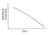
- FIG. 2 is a graph of power transmitted vs. fiber position for prior art apparatus.
- FIG. 3 is an illustrative embodiment in accordance with the principles of this invention.
- FIG. 4 is a graph of refractive index variation with distance from the launch end of a fiber in accordance with the principles of this invention.
- FIG. 5 is a plot of power transmitted vs. fiber position that results when light is launched into a fiber the refractive index Of which varies as shown in FIG. 4 .
- FIG. 6 is a block diagram of a system using the fiber of FIGS. 1 and 3 .
- FIG. 7 is a block diagram of a further system using the fiber of FIGS. 1 and 3 .
- FIG. 8 is a plot of energy loss vs. fiber position that results when light is launched into the fiber of FIG. 5 when a section of the fiber is exposed to a target chemical substance.
- FIG. 9 is a plot of chemical concentration vs. fiber position that can be derived from FIG. 8 .
- Multi-mode absorption based distributed sensors have an output response given by P ⁇ P o ⁇ ⁇ V ⁇ ⁇ ⁇ l ( 1 ) as is well known.
- Equation (1) is the generic response, which can be observed as a change in total transmitted light intensity using a simple detection scheme, observed as a plot of backscattered power versus length in an optical time domain reflectometer (OTDR), of a multi-mode optical fiber with an absorbing cladding. It is clear that the power lost per unit length at each position along a distributed optical fiber sensor is different from the power lost per unit length at any other position along the fiber.
- OTDR optical time domain reflectometer
- FIG. 1 shows a representative distributed optical fiber sensor.
- a distributed, multi-mode optical fiber sensor can be made to exhibit a linear response in the dB scale.
- a linear response to changes in absorption may be achieved by compensating for the absorption fall off of FIG. 2 by:
- FIG. 2 is a plot of power radiated per unit length versus fiber length l for a typical multimode fiber.
- the absorption coefficient clearly falls off.
- the absorption coefficient change is due to the fact that all modes in an optical fiber are attenuated differently. Modes closer to cut off (i.e., modes that have an angle of incidence in the core/cladding boundary closer to 90 degrees) are attenuated quicker than modes far from cut off. In order to obtain an even attenuation as a function of length, coupling from lower order modes to higher order modes must occur. Even attenuation is achieved, for example, by increasing the core diameter as shown in FIG. 3 or by varying the core/cladding refractive index ratio or by increasing the absorption coefficient or scattering coefficient along the length of the fiber to compensate for the lower attenuation rate of modes that are increasingly far from cut off.
- FIG. 4 is a plot of n co /n cla versus fiber length for a multi-mode, distributed sensor optical fiber in accordance with the principles of this invention. It is clear that an optical fiber so designed exhibits a power loss which is linear over the length of the fiber, for the combined effect of the spatial transient of FIG. 2 and the length-variation of fiber physical parameters (e.g., the refractive index, as shown in FIG. 4 ) is to linearize the power versus length curve ( FIG. 5 ), thus creating a fiber sensor the sensitivity of which does not vary as a function of length.
- the refractive index as shown in FIG. 4
- FIG. 6 is a block diagram of sensor apparatus employing a fiber optic sensor of the type shown in FIG. 4 .
- the fiber 100 includes a core 125 transmissive of electromagnetic radiation (e.g. light) and a cladding or sheath 126 of a permeable material.
- the index of refraction of sheath 126 is lower than that of core 125 , and may vary with length.
- the fiber may include a coating 127 which also would be of a permeable material.
- a reactant to be detected causes a change of, for example, the intensity of light back scattered toward the end into which light is launched.
- the input light is launched, and the output light is detected by detector 131 as noted herein before.
- Light energy is introduced at the input end of the fiber by, illustratively, a laser 132 and the properties of the light energy (e.g. intensity, wavelength - - -) are modified by interaction between material in the fiber sheath and the reactant to generate backscattered light characteristic of the reactant and the interaction with the sheath material.
- properties of the light energy e.g. intensity, wavelength - - -
- An optical fiber structured in accordance with this invention to exhibit a length-invariant response to such interactions is also advantageous for illumination applications and for applications in which an accumulated response is desired as in U.S. Pat. No. 4,321,057 issued Mar. 23, 1982 and in the above noted U.S. Pat. No. 4,834,496 where the portion of the length of fiber affected may be compared to some threshold for triggering an alarm.
- An optical fiber having a core of F-2 Schott glass with a diameter of 100 micrometers and a cladding of polymer with a thickness of 20 micrometers was fabricated and a twenty meter length of the fiber was tested at 850 nm (active wavelength) as a moisture sensor.
- a reference wavelength of 1300 nm also was used.
- a dry reference measurement was made and then increasing lengths of 10 cm, 20 cm, and 50 cm were wetted. A final reading was taken after allowing the 50 cm wet length to air dry for one hour.
- At 1300 nm only a slight change ( ⁇ 1 dB) in output intensity occurs after an input signal propagates more than 10 meters along the fiber.
- a significant change of 2.4 dB is detected at 850 nm.
- the OTDR was able to determine the location of the moisture site to within 1 cm using 850 nm light and the 1300 nm light was capable of being used to compensate for transmission charges due to effects other than moisture.
- a PH-sensitive fiber was also tested, in a manner similar to that for the moisture-sensitive fiber, immersed in PH-7 and PH-10 buffer solutions. At 1300 nm there was virtually no change in output intensity. At 850 nm a substantial change of 1.2 dB occurred. The OTDR was able to locate the position of the buffer solution along the fiber to within 2 cms at 850 nm, and again the 1300 nm signal could be used as a “reference”.
- the ability to structure a fiber to control the fraction of light lost per unit length in accordance with the principles of this invention also permits a fiber to be constructed to provide an arbitrary power loss profile along the fiber.
- a fiber sensor may be provided which is particularly sensitive at a predesignated position in the fiber.
Landscapes
- Physics & Mathematics (AREA)
- General Physics & Mathematics (AREA)
- Chemical & Material Sciences (AREA)
- Analytical Chemistry (AREA)
- General Health & Medical Sciences (AREA)
- Plasma & Fusion (AREA)
- Health & Medical Sciences (AREA)
- Life Sciences & Earth Sciences (AREA)
- Engineering & Computer Science (AREA)
- Biochemistry (AREA)
- Chemical Kinetics & Catalysis (AREA)
- Immunology (AREA)
- Pathology (AREA)
- Optics & Photonics (AREA)
- Optical Transform (AREA)
- Measuring Temperature Or Quantity Of Heat (AREA)
- Optical Fibers, Optical Fiber Cores, And Optical Fiber Bundles (AREA)
- Investigating Or Analysing Materials By Optical Means (AREA)
- Light Guides In General And Applications Therefor (AREA)
Abstract
Description
as is well known. In the equation, V is the fiber number given by
V=ka√{square root over (n co 2 −n cla 2 )}, (2)
where Po is the power at the input end of the fiber, P is the power at a distance l from the input end, a is the core radius, α is the absorption coefficient of the cladding, and nco and ncla are the core and cladding refractive indices. Equation (1) is the generic response, which can be observed as a change in total transmitted light intensity using a simple detection scheme, observed as a plot of backscattered power versus length in an optical time domain reflectometer (OTDR), of a multi-mode optical fiber with an absorbing cladding. It is clear that the power lost per unit length at each position along a distributed optical fiber sensor is different from the power lost per unit length at any other position along the fiber.
-
- a) increasing the core/cladding refractive index ratio along the fiber length
- b) increasing the core diameter along the fiber length
- c) increasing the absorption coefficient of the sensor material in the cladding along the fiber length
- d) increasing the absorption coefficient of the cladding along the fiber length
- e) increasing the scattering coefficient of the core along the fiber length
- f) varying the parameters (a,b & c) together or in varying combinations
Claims (11)
Priority Applications (3)
| Application Number | Priority Date | Filing Date | Title |
|---|---|---|---|
| US10/717,080 US7006718B2 (en) | 1999-06-16 | 2003-11-19 | Distributed optical fiber sensor with controlled response |
| US11/364,237 US7260283B2 (en) | 1999-06-16 | 2006-02-28 | Distributed optical fiber sensor with controlled response |
| US11/842,906 US7650051B2 (en) | 1999-06-16 | 2007-08-21 | Distributed optical fiber sensor with controlled response |
Applications Claiming Priority (3)
| Application Number | Priority Date | Filing Date | Title |
|---|---|---|---|
| US09/334,845 US6205263B1 (en) | 1999-06-16 | 1999-06-16 | Distributed optical fiber sensor with controlled response |
| US09/730,158 US20020018629A1 (en) | 1999-06-16 | 2000-12-05 | Distributed optical fiber sensor with controlled power loss |
| US10/717,080 US7006718B2 (en) | 1999-06-16 | 2003-11-19 | Distributed optical fiber sensor with controlled response |
Related Parent Applications (2)
| Application Number | Title | Priority Date | Filing Date |
|---|---|---|---|
| US09/730,158 Continuation US20020018629A1 (en) | 1999-06-16 | 2000-12-05 | Distributed optical fiber sensor with controlled power loss |
| US09730158 Continuation | 2002-12-05 |
Related Child Applications (2)
| Application Number | Title | Priority Date | Filing Date |
|---|---|---|---|
| US11/364,237 Continuation US7260283B2 (en) | 1999-06-16 | 2006-02-28 | Distributed optical fiber sensor with controlled response |
| US11/364,237 Division US7260283B2 (en) | 1999-06-16 | 2006-02-28 | Distributed optical fiber sensor with controlled response |
Publications (2)
| Publication Number | Publication Date |
|---|---|
| US20050053344A1 US20050053344A1 (en) | 2005-03-10 |
| US7006718B2 true US7006718B2 (en) | 2006-02-28 |
Family
ID=23309113
Family Applications (6)
| Application Number | Title | Priority Date | Filing Date |
|---|---|---|---|
| US09/334,845 Expired - Lifetime US6205263B1 (en) | 1999-06-16 | 1999-06-16 | Distributed optical fiber sensor with controlled response |
| US09/685,387 Expired - Fee Related US6714711B1 (en) | 1999-06-16 | 2000-10-10 | Optical waveguide illuminator |
| US09/730,158 Abandoned US20020018629A1 (en) | 1999-06-16 | 2000-12-05 | Distributed optical fiber sensor with controlled power loss |
| US10/717,080 Expired - Lifetime US7006718B2 (en) | 1999-06-16 | 2003-11-19 | Distributed optical fiber sensor with controlled response |
| US11/364,237 Expired - Fee Related US7260283B2 (en) | 1999-06-16 | 2006-02-28 | Distributed optical fiber sensor with controlled response |
| US11/842,906 Expired - Fee Related US7650051B2 (en) | 1999-06-16 | 2007-08-21 | Distributed optical fiber sensor with controlled response |
Family Applications Before (3)
| Application Number | Title | Priority Date | Filing Date |
|---|---|---|---|
| US09/334,845 Expired - Lifetime US6205263B1 (en) | 1999-06-16 | 1999-06-16 | Distributed optical fiber sensor with controlled response |
| US09/685,387 Expired - Fee Related US6714711B1 (en) | 1999-06-16 | 2000-10-10 | Optical waveguide illuminator |
| US09/730,158 Abandoned US20020018629A1 (en) | 1999-06-16 | 2000-12-05 | Distributed optical fiber sensor with controlled power loss |
Family Applications After (2)
| Application Number | Title | Priority Date | Filing Date |
|---|---|---|---|
| US11/364,237 Expired - Fee Related US7260283B2 (en) | 1999-06-16 | 2006-02-28 | Distributed optical fiber sensor with controlled response |
| US11/842,906 Expired - Fee Related US7650051B2 (en) | 1999-06-16 | 2007-08-21 | Distributed optical fiber sensor with controlled response |
Country Status (1)
| Country | Link |
|---|---|
| US (6) | US6205263B1 (en) |
Cited By (1)
| Publication number | Priority date | Publication date | Assignee | Title |
|---|---|---|---|---|
| US20060147149A1 (en) * | 1999-06-16 | 2006-07-06 | Lieberman Robert A | Distributed optical fiber sensor with controlled response |
Families Citing this family (87)
| Publication number | Priority date | Publication date | Assignee | Title |
|---|---|---|---|---|
| GB9928696D0 (en) * | 1999-12-03 | 2000-02-02 | Swan Thomas & Co Ltd | Optical devices and methods of manufacture thereof |
| US7233739B2 (en) * | 2001-10-22 | 2007-06-19 | Patel C Kumar N | Optical bit stream reader system |
| AU2002951256A0 (en) * | 2002-09-06 | 2002-09-19 | Poly Optics Australia Pty Ltd | Improvements in side-scattering light guides |
| US6965708B2 (en) * | 2002-10-04 | 2005-11-15 | Luna Innovations, Inc. | Devices, systems, and methods for sensing moisture |
| EP1575452A2 (en) * | 2002-12-09 | 2005-09-21 | Oree, Advanced Illumination Solutions Inc. | Flexible optical device |
| US7194184B2 (en) * | 2003-03-10 | 2007-03-20 | Fiberstars Incorporated | Light pipe with side-light extraction |
| JP4261376B2 (en) * | 2004-01-28 | 2009-04-30 | 富士フイルム株式会社 | Sheet-like light guide and communication system using the same |
| JP2005215169A (en) * | 2004-01-28 | 2005-08-11 | Fuji Photo Film Co Ltd | Communication system using sheet-like light guide |
| JP4153441B2 (en) * | 2004-01-28 | 2008-09-24 | 富士フイルム株式会社 | Sheet-like light guide and communication system using the same |
| JP4308050B2 (en) * | 2004-03-18 | 2009-08-05 | 三洋電機株式会社 | Optical waveguide |
| US7473906B2 (en) * | 2005-04-28 | 2009-01-06 | Claudio Oliveira Egalon | Reversible, low cost, distributed optical fiber sensor with high spatial resolution |
| US9297092B2 (en) | 2005-06-05 | 2016-03-29 | Qd Vision, Inc. | Compositions, optical component, system including an optical component, devices, and other products |
| WO2010014205A1 (en) * | 2008-07-28 | 2010-02-04 | Qd Vision, Inc. | Compositions, optical component, system including an optional component, devices, and other products |
| US8718437B2 (en) * | 2006-03-07 | 2014-05-06 | Qd Vision, Inc. | Compositions, optical component, system including an optical component, devices, and other products |
| US8845927B2 (en) * | 2006-06-02 | 2014-09-30 | Qd Vision, Inc. | Functionalized nanoparticles and method |
| US8272758B2 (en) * | 2005-06-07 | 2012-09-25 | Oree, Inc. | Illumination apparatus and methods of forming the same |
| US8215815B2 (en) * | 2005-06-07 | 2012-07-10 | Oree, Inc. | Illumination apparatus and methods of forming the same |
| US8128272B2 (en) | 2005-06-07 | 2012-03-06 | Oree, Inc. | Illumination apparatus |
| US7551810B2 (en) * | 2005-09-22 | 2009-06-23 | Optech Ventures, Llc | Segmented fiber optic sensor and method |
| US7583865B2 (en) * | 2005-09-22 | 2009-09-01 | Optech Ventures, Llc | Segmented fiber optic sensor and method |
| US9701899B2 (en) | 2006-03-07 | 2017-07-11 | Samsung Electronics Co., Ltd. | Compositions, optical component, system including an optical component, devices, and other products |
| US9874674B2 (en) | 2006-03-07 | 2018-01-23 | Samsung Electronics Co., Ltd. | Compositions, optical component, system including an optical component, devices, and other products |
| US9951438B2 (en) | 2006-03-07 | 2018-04-24 | Samsung Electronics Co., Ltd. | Compositions, optical component, system including an optical component, devices, and other products |
| US8849087B2 (en) * | 2006-03-07 | 2014-09-30 | Qd Vision, Inc. | Compositions, optical component, system including an optical component, devices, and other products |
| CN100383580C (en) * | 2006-03-23 | 2008-04-23 | 南京邮电大学 | Whole body uniform illuminating optical fiber and preparing method thereof |
| US9212056B2 (en) | 2006-06-02 | 2015-12-15 | Qd Vision, Inc. | Nanoparticle including multi-functional ligand and method |
| EP1887389A3 (en) * | 2006-08-11 | 2008-03-05 | LG Electronics Inc. | Light pipe having a structure of enhancing an emission of a light |
| US7565050B2 (en) | 2006-10-13 | 2009-07-21 | Lg Electronics, Inc. | Light pipe having an improved structure of prisms |
| WO2008063658A2 (en) | 2006-11-21 | 2008-05-29 | Qd Vision, Inc. | Semiconductor nanocrystals and compositions and devices including same |
| WO2008063652A1 (en) | 2006-11-21 | 2008-05-29 | Qd Vision, Inc. | Blue emitting semiconductor nanocrystals and compositions and devices including same |
| US7483144B2 (en) * | 2007-03-02 | 2009-01-27 | Honeywell International, Inc. | Apparatus and method for resonant chemical and biological sensing |
| KR101672553B1 (en) | 2007-06-25 | 2016-11-03 | 큐디 비젼, 인크. | Compositions and methods including depositing nanomaterial |
| WO2009014707A2 (en) | 2007-07-23 | 2009-01-29 | Qd Vision, Inc. | Quantum dot light enhancement substrate and lighting device including same |
| US8128249B2 (en) * | 2007-08-28 | 2012-03-06 | Qd Vision, Inc. | Apparatus for selectively backlighting a material |
| US8550684B2 (en) * | 2007-12-19 | 2013-10-08 | Oree, Inc. | Waveguide-based packaging structures and methods for discrete lighting elements |
| US7929816B2 (en) | 2007-12-19 | 2011-04-19 | Oree, Inc. | Waveguide sheet containing in-coupling, propagation, and out-coupling regions |
| US8231237B2 (en) * | 2008-03-05 | 2012-07-31 | Oree, Inc. | Sub-assembly and methods for forming the same |
| WO2009151515A1 (en) | 2008-05-06 | 2009-12-17 | Qd Vision, Inc. | Solid state lighting devices including quantum confined semiconductor nanoparticles |
| WO2009137053A1 (en) | 2008-05-06 | 2009-11-12 | Qd Vision, Inc. | Optical components, systems including an optical component, and devices |
| US9207385B2 (en) | 2008-05-06 | 2015-12-08 | Qd Vision, Inc. | Lighting systems and devices including same |
| JP5218126B2 (en) * | 2008-05-19 | 2013-06-26 | Toto株式会社 | Wash counter |
| US8301002B2 (en) * | 2008-07-10 | 2012-10-30 | Oree, Inc. | Slim waveguide coupling apparatus and method |
| US8297786B2 (en) | 2008-07-10 | 2012-10-30 | Oree, Inc. | Slim waveguide coupling apparatus and method |
| US10080499B2 (en) * | 2008-07-30 | 2018-09-25 | Medtronic, Inc. | Implantable medical system including multiple sensing modules |
| US20100098377A1 (en) * | 2008-10-16 | 2010-04-22 | Noam Meir | Light confinement using diffusers |
| WO2010051553A1 (en) * | 2008-11-03 | 2010-05-06 | Polytech Institute Of New York University | Gas leak detection system and methods |
| US8463083B2 (en) * | 2009-01-30 | 2013-06-11 | Claudio Oliveira Egalon | Side illuminated multi point multi parameter optical fiber sensor |
| US20100208470A1 (en) * | 2009-02-10 | 2010-08-19 | Yosi Shani | Overlapping illumination surfaces with reduced linear artifacts |
| US8624527B1 (en) | 2009-03-27 | 2014-01-07 | Oree, Inc. | Independently controllable illumination device |
| JP5710597B2 (en) | 2009-04-28 | 2015-04-30 | キユーデイー・ビジヨン・インコーポレーテツド | Optical material, optical component and method |
| US7952772B2 (en) * | 2009-05-08 | 2011-05-31 | Honeywell International Inc. | Photonic crystal fiber sensor |
| US20100320904A1 (en) * | 2009-05-13 | 2010-12-23 | Oree Inc. | LED-Based Replacement Lamps for Incandescent Fixtures |
| WO2010150202A2 (en) | 2009-06-24 | 2010-12-29 | Oree, Advanced Illumination Solutions Inc. | Illumination apparatus with high conversion efficiency and methods of forming the same |
| KR20120062773A (en) | 2009-08-14 | 2012-06-14 | 큐디 비젼, 인크. | Lighting devices, an optical component for a lighting device, and methods |
| CN105974513B (en) | 2009-11-20 | 2022-10-14 | 康宁股份有限公司 | Illumination system with side-emitting optical photonic fibers and method of making same |
| DE102010000308B4 (en) * | 2010-02-04 | 2012-05-31 | Bundesanstalt für Materialforschung und -Prüfung (BAM) | Humidity sensor and method for moisture measurement |
| US9476760B2 (en) * | 2010-06-25 | 2016-10-25 | Schlumberger Technology Corporation | Precision measurements in a fiber optic distributed sensor system |
| US8924158B2 (en) | 2010-08-09 | 2014-12-30 | Schlumberger Technology Corporation | Seismic acquisition system including a distributed sensor having an optical fiber |
| US10401343B1 (en) | 2010-09-28 | 2019-09-03 | Optech Ventures, Llc. | Gas sensing chemistry and sensors and sensing systems and method |
| US8724942B2 (en) * | 2011-04-26 | 2014-05-13 | Corning Incorporated | Light-coupling optical systems and methods employing light-diffusing optical fiber |
| US8787717B2 (en) * | 2011-04-26 | 2014-07-22 | Corning Incorporated | Systems and methods for coupling light into a transparent sheet |
| ES2787826T3 (en) | 2011-04-28 | 2020-10-19 | L E S S Ltd | Waveguide devices for lighting systems |
| US8591072B2 (en) | 2011-11-16 | 2013-11-26 | Oree, Inc. | Illumination apparatus confining light by total internal reflection and methods of forming the same |
| US9958136B2 (en) * | 2012-01-27 | 2018-05-01 | Rockwell Automation Technologies, Inc. | Sensor device with indicator and related methods |
| US9297935B2 (en) | 2012-01-27 | 2016-03-29 | Rockwell Automation Technologies, Inc. | Method and device for enhancing sensor indication |
| CN103454847B (en) * | 2012-05-29 | 2016-05-18 | 杨文君 | Slab guide display and system |
| US9929325B2 (en) | 2012-06-05 | 2018-03-27 | Samsung Electronics Co., Ltd. | Lighting device including quantum dots |
| WO2014006501A1 (en) | 2012-07-03 | 2014-01-09 | Yosi Shani | Planar remote phosphor illumination apparatus |
| JP6273006B2 (en) | 2013-07-15 | 2018-01-31 | エル イー エス エス・リミテッド | Coherent optical waveguide illumination system with speckle noise reducer |
| US9321222B2 (en) | 2013-08-13 | 2016-04-26 | Baker Hughes Incorporated | Optical fiber sensing with enhanced backscattering |
| JP5907935B2 (en) * | 2013-09-03 | 2016-04-26 | キヤノン・コンポーネンツ株式会社 | Illumination apparatus, image sensor unit, image reading apparatus, and image forming apparatus |
| ES2864634T3 (en) | 2013-10-18 | 2021-10-14 | L E S S Ltd | Waveguide based lighting fixture |
| US9207397B2 (en) | 2013-11-14 | 2015-12-08 | Corning Incorporated | Light diffusing fiber with low melting temperature glass |
| US9389426B2 (en) | 2013-11-22 | 2016-07-12 | Tyco Electronics Canada Ulc | Light consolidation assembly |
| CN104091604A (en) * | 2014-06-26 | 2014-10-08 | 南京邮电大学 | Waveguide fluorescent data memory, manufacturing method and data reading method |
| US9857515B2 (en) | 2014-07-28 | 2018-01-02 | Corning Incorporated | Side-emitting optical fiber system and assembly with light-emitting jacket members |
| DE102014114521A1 (en) * | 2014-10-07 | 2016-04-07 | Bundesrepublik Deutschland, Vertreten Durch Den Bundesminister Für Wirtschaft Und Energie, Dieser Vertreten Durch Den Präsidenten Der Bundesanstalt Für Materialforschung Und -Prüfung (Bam) | Method for the spatially resolved measurement of molecular concentrations and / or temperature by means of optical fibers |
| CN104456313A (en) * | 2014-12-03 | 2015-03-25 | 合肥京东方显示光源有限公司 | Backlight module and display device |
| CN110073174B (en) | 2016-12-29 | 2022-04-26 | 直观外科手术操作公司 | Method and apparatus for determining shape parameters using a sensing optical fiber having a single core with multiple light propagation modes |
| US11202590B2 (en) | 2017-04-09 | 2021-12-21 | Intelligent Optical Systems, Inc. | Sensor integrated biopsy needle system |
| EP3737258B1 (en) * | 2018-01-10 | 2025-03-12 | Koninklijke Philips N.V. | Laser-enhanced optical element |
| US11009657B2 (en) | 2018-09-10 | 2021-05-18 | Nlight, Inc. | Optical fiber splice encapsulated by a cladding light stripper |
| EP3841411B1 (en) * | 2018-09-21 | 2024-11-06 | NLIGHT, Inc. | Optical fiber cladding light stripper |
| CN111070624A (en) * | 2020-01-04 | 2020-04-28 | 深圳市圣诺光电科技有限公司 | A large core diameter polymer side light optical fiber and optical cable manufacturing equipment |
| JP2023510777A (en) * | 2020-01-10 | 2023-03-15 | オーエフエス ファイテル,エルエルシー | Enhanced high-temperature hydrogen scattering resistance in optical fibers |
| CN111676532B (en) * | 2020-06-10 | 2022-03-01 | 华中科技大学 | Luminescent fiber, preparation method and application thereof, and luminescent mask |
| CN117063102A (en) * | 2021-02-12 | 2023-11-14 | Ofs菲特尔有限责任公司 | System and method for enhanced backscatter in an optical fiber with hermeticity |
Citations (4)
| Publication number | Priority date | Publication date | Assignee | Title |
|---|---|---|---|---|
| US4560248A (en) * | 1981-08-14 | 1985-12-24 | Imperial Chemical Industries, Plc | Fibre optic sensor with bonded dye |
| US4881793A (en) * | 1987-06-04 | 1989-11-21 | Pirelli General Plc | Optical fibre attenuators and method for making same |
| US5572618A (en) * | 1994-07-13 | 1996-11-05 | Lucent Technologies Inc. | Optical attenuator |
| US5995686A (en) * | 1997-12-16 | 1999-11-30 | Hamburger; Robert N. | Fiber-optic sensor device and method |
Family Cites Families (11)
| Publication number | Priority date | Publication date | Assignee | Title |
|---|---|---|---|---|
| US4321057A (en) * | 1979-09-20 | 1982-03-23 | Buckles Richard G | Method for quantitative analysis using optical fibers |
| US4834496A (en) * | 1987-05-22 | 1989-05-30 | American Telephone And Telegraph Company, At&T Bell Laboratories | Optical fiber sensors for chemical detection |
| US5224182A (en) * | 1991-08-29 | 1993-06-29 | Virginia Polytechnic Institute And State University | Spatially-weighted two-mode optical fiber sensors |
| FR2707285B1 (en) * | 1993-07-06 | 1995-08-11 | Alcatel Fibres Optiques | Preform for optical fiber, process for manufacturing such a preform and optical fiber obtained from this preform. |
| US5737472A (en) * | 1993-12-17 | 1998-04-07 | Audio-Images S.A.R.L. | Optical fiber with multiple point lateral illumination |
| GB9503781D0 (en) * | 1994-05-19 | 1995-04-12 | Univ Southampton | External cavity laser |
| US5845038A (en) * | 1997-01-28 | 1998-12-01 | Minnesota Mining And Manufacturing Company | Optical fiber illumination system |
| JPH10206640A (en) * | 1997-01-28 | 1998-08-07 | Nec Corp | Light fixing/damping device |
| US5905837A (en) * | 1997-07-22 | 1999-05-18 | Nec Usa, Inc. | Side emitting optical fiber |
| JPH11326644A (en) * | 1998-05-20 | 1999-11-26 | Bridgestone Corp | Light transmission tube and its production |
| US6205263B1 (en) * | 1999-06-16 | 2001-03-20 | Intelligent Optical Systems | Distributed optical fiber sensor with controlled response |
-
1999
- 1999-06-16 US US09/334,845 patent/US6205263B1/en not_active Expired - Lifetime
-
2000
- 2000-10-10 US US09/685,387 patent/US6714711B1/en not_active Expired - Fee Related
- 2000-12-05 US US09/730,158 patent/US20020018629A1/en not_active Abandoned
-
2003
- 2003-11-19 US US10/717,080 patent/US7006718B2/en not_active Expired - Lifetime
-
2006
- 2006-02-28 US US11/364,237 patent/US7260283B2/en not_active Expired - Fee Related
-
2007
- 2007-08-21 US US11/842,906 patent/US7650051B2/en not_active Expired - Fee Related
Patent Citations (4)
| Publication number | Priority date | Publication date | Assignee | Title |
|---|---|---|---|---|
| US4560248A (en) * | 1981-08-14 | 1985-12-24 | Imperial Chemical Industries, Plc | Fibre optic sensor with bonded dye |
| US4881793A (en) * | 1987-06-04 | 1989-11-21 | Pirelli General Plc | Optical fibre attenuators and method for making same |
| US5572618A (en) * | 1994-07-13 | 1996-11-05 | Lucent Technologies Inc. | Optical attenuator |
| US5995686A (en) * | 1997-12-16 | 1999-11-30 | Hamburger; Robert N. | Fiber-optic sensor device and method |
Cited By (2)
| Publication number | Priority date | Publication date | Assignee | Title |
|---|---|---|---|---|
| US20060147149A1 (en) * | 1999-06-16 | 2006-07-06 | Lieberman Robert A | Distributed optical fiber sensor with controlled response |
| US7260283B2 (en) * | 1999-06-16 | 2007-08-21 | Optech Ventures, Llc | Distributed optical fiber sensor with controlled response |
Also Published As
| Publication number | Publication date |
|---|---|
| US7260283B2 (en) | 2007-08-21 |
| US20070286547A1 (en) | 2007-12-13 |
| US20020018629A1 (en) | 2002-02-14 |
| US6714711B1 (en) | 2004-03-30 |
| US20050053344A1 (en) | 2005-03-10 |
| US6205263B1 (en) | 2001-03-20 |
| US20060147149A1 (en) | 2006-07-06 |
| US7650051B2 (en) | 2010-01-19 |
Similar Documents
| Publication | Publication Date | Title |
|---|---|---|
| US7006718B2 (en) | Distributed optical fiber sensor with controlled response | |
| US5191206A (en) | Distributed fiber optic sensor using clad material light backscattering | |
| Villatoro et al. | High resolution refractive index sensing with cladded multimode tapered optical fibre | |
| US4203326A (en) | Method and means for improved optical temperature sensor | |
| US5627934A (en) | Concentric core optical fiber with multiple-mode signal transmission | |
| Wang et al. | A high-temperature humidity sensor based on a singlemode-side polished multimode-singlemode fiber structure | |
| US8873060B2 (en) | Water-in-fuel sensor | |
| Zhang et al. | Water detection in jet fuel using a polymer optical fibre Bragg grating | |
| CA2932473A1 (en) | Gas sensor | |
| US4714829A (en) | Fibre optic sensing device and method | |
| Grobnic et al. | Bragg grating evanescent field sensor made in biconical tapered fiber with femtosecond IR radiation | |
| Remouche et al. | Intrinsic integrated optical temperature sensor based on waveguide bend loss | |
| Khanikar et al. | Reflectance-based no core fiber sensor with enhanced Sensitivity for salinity detection | |
| Neves et al. | Humidity-insensitive optical fibers for distributed sensing applications | |
| Kvasnik et al. | Distributed chemical sensing utilising evanescent wave interactions | |
| CN108318452A (en) | A kind of cone of intensity modulation type four light fibre humidity transducer | |
| Bariain et al. | Experimental results toward development of humidity sensors by using a hygroscopic material on biconically tapered optical fiber | |
| Sasaki et al. | Sensitivity property of a hetero-core-spliced fiber optic displacement sensor | |
| Tan et al. | High relative humidity sensing using gelatin-coated long period grating | |
| Saunders et al. | Distributed plastic optical fibre measurement of pH using a photon counting OTDR | |
| Marinah et al. | Agricultural soil moisture sensor based on U-bend Plastic Optical Fibre (POF) | |
| Chiadini et al. | A reflectometric optical fiber temperature sensor | |
| Mizuno et al. | Pilot demonstration of refractive index sensing using polymer optical fiber crushed with slotted screwdriver | |
| Szolga | Humidity and isopropyl alcohol detection sensor based on plastic optical fiber | |
| Lieberman et al. | Intrinsic fiber optic sensor for distributed water detection |
Legal Events
| Date | Code | Title | Description |
|---|---|---|---|
| AS | Assignment |
Owner name: INTELLIGENT OPTICAL SYSTEMS, INC., CALIFORNIA Free format text: ASSIGNMENT OF ASSIGNORS INTEREST;ASSIGNORS:LIEBERMAN, ROBERT A.;EGALON, CLAUDIO O.;REEL/FRAME:017241/0743 Effective date: 19990610 |
|
| STCF | Information on status: patent grant |
Free format text: PATENTED CASE |
|
| FPAY | Fee payment |
Year of fee payment: 4 |
|
| AS | Assignment |
Owner name: OPTECH VENTURES, LLC, CALIFORNIA Free format text: ASSIGNMENT OF ASSIGNORS INTEREST;ASSIGNOR:INTELLIGENT OPTICAL SYSTEMS, INC.;REEL/FRAME:027816/0058 Effective date: 20071002 |
|
| REMI | Maintenance fee reminder mailed | ||
| FPAY | Fee payment |
Year of fee payment: 8 |
|
| SULP | Surcharge for late payment |
Year of fee payment: 7 |
|
| MAFP | Maintenance fee payment |
Free format text: PAYMENT OF MAINTENANCE FEE, 12TH YR, SMALL ENTITY (ORIGINAL EVENT CODE: M2553) Year of fee payment: 12 |