US700443A - Concrete-and-metal skeleton for building purposes. - Google Patents
Concrete-and-metal skeleton for building purposes. Download PDFInfo
- Publication number
- US700443A US700443A US6923601A US1901069236A US700443A US 700443 A US700443 A US 700443A US 6923601 A US6923601 A US 6923601A US 1901069236 A US1901069236 A US 1901069236A US 700443 A US700443 A US 700443A
- Authority
- US
- United States
- Prior art keywords
- wires
- supports
- distribution
- concrete
- metal
- Prior art date
- Legal status (The legal status is an assumption and is not a legal conclusion. Google has not performed a legal analysis and makes no representation as to the accuracy of the status listed.)
- Expired - Lifetime
Links
Images

Classifications
-
- E—FIXED CONSTRUCTIONS
- E04—BUILDING
- E04B—GENERAL BUILDING CONSTRUCTIONS; WALLS, e.g. PARTITIONS; ROOFS; FLOORS; CEILINGS; INSULATION OR OTHER PROTECTION OF BUILDINGS
- E04B5/00—Floors; Floor construction with regard to insulation; Connections specially adapted therefor
- E04B5/16—Load-carrying floor structures wholly or partly cast or similarly formed in situ
- E04B5/17—Floor structures partly formed in situ
- E04B5/23—Floor structures partly formed in situ with stiffening ribs or other beam-like formations wholly or partly prefabricated
- E04B5/29—Floor structures partly formed in situ with stiffening ribs or other beam-like formations wholly or partly prefabricated the prefabricated parts of the beams consisting wholly of metal
Definitions
- the Object of the present invention is to enable fine metal wire to be used forsupporting constructions made of concrete, mortar,- &c., in accordance with the suppositions of the static calculations.
- the presentinvention has-for its object to procure stability in the wires in a very sim'-- ple and consequently profitable manner by tension without'the complete building being;
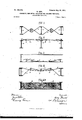
- FIG. 4 shows another form of construction of the device.
- Fig. 4. shows a mold for supporting the distribution-supports 12 during the mounting.
- Fig. 5 shows another form of construction in horizontal projection and vertical section without fixed girders a.
- Fig. 6 shows a form of construction in which the secondary distribution-supports b are employed.
- the wires may not have their power of resistance diminished for the com- While giving the tension each wire plete building by the turning upward of the distribu tion-sup ports bthat is to say, for example, in the use of iron wire in order that the tension on mounting will not exceed five hundredkilos per square centimeter, the folas to indirect burdens,a nd consequently if the construction, Figs. 1 or 2, receives for static reasons the samenu mberof wires above the distribution-supports b as beneath, or if, as in Fig.
- thepassage ot the wires is only effected on oneside, the height ot'the axis of the distribution-supports remaining invariable by the provision of distributionsupports b in perforations e, the distribution-supports lowing method is adopted: If the finished building will be submitted to direct as Well b are proportionate. iuftheir cross-ineasurements in such a way that the turning or ele vation of the said supportsin the direction of their smallest to their largest cross-section only causes a stretching of the wires correspondin g to a strain on the material constituting the said wire equal at most to the allowed strain less by the strain to which the wire in thebuildingof metal and concrete will be exposed.
- Fig. 5 of the accompanying drawings shows an amplification of the useof the distributionsupports 1).
- a space contained by four walls or more is covered by a smooth sheet of concrete and metal,using all the delineation-lines available as supports and dispensing with all framing of joists made of double T-irons, be.
- the distribution-s11 pports b are laid flatin the ceiling, ashereinbefore described, and secondary distribution-supports b are placed between them in such a way that the distribution-snpports I) pass underneath the distribntion-supports I). Then the metal wires a and c are so placed that they cross each other, as shown in the drawings, and finally the distrilmtion-supports b are turned edge upward. In this way the dis tribution-supports i) press down the secondary distribution-s11pports b, which pass under them, and thus directly stretch the secondary wires 0 For the rest the strain of mounting is adjusted just as for the present and other constructions.
Landscapes
- Engineering & Computer Science (AREA)
- Architecture (AREA)
- Physics & Mathematics (AREA)
- Electromagnetism (AREA)
- Civil Engineering (AREA)
- Structural Engineering (AREA)
- Wire Processing (AREA)
- Panels For Use In Building Construction (AREA)
- Forms Removed On Construction Sites Or Auxiliary Members Thereof (AREA)
Description
No. 700,443.- Patented May 20, I902. 1 0. RUHL.
co'ucnan: AND METAL-SKELETON F08 BUILDING PunPosEs.
I (Application filed July 22, 1901.) (no'modem v 2 Sheets-sheaf Y @2- fizz/i! Patented Nay 20,1902
2 Sheets-sheet 2.-
nvmlm:
@ QQ I E o. RUH L. CONCRETE AND METAL SKELETON FUR BUILDING PURPOSES.
v (Application filed July 22, 1901.)
' (No Model.)
UNITED STATES- PATENT OFFICE. i
or'ro RUHL, or BREMEN, GERMANY.
CONCRETE-AND -METAL S KELETON FOR BUlLDlNG PURPOSES.
SIECIFIGATION formingpart of Letters Patent N 0. 700,443, dated May 20, 1902.
Application filed July 22, 1901. Serial No. 69.236. (No me...)
To all whom it may concern:'
Be it known that I, OTTO RUHL -a subject. of the German Emperor, and a resident 0f" Bremen, Germany, haveinvented certain new,
and useful-Improvements in Concrete-and,
Metal Skeletons for Building Purposes, of
which the following is a specification.
, The Object of the present invention is to enable fine metal wire to be used forsupporting constructions made of concrete, mortar,- &c., in accordance with the suppositions of the static calculations.
The presentinvention has-for its object to procure stability in the wires in a very sim'-- ple and consequently profitable manner by tension without'the complete building being;
4 shows another form of construction of the device. Fig. 4. shows a mold for supporting the distribution-supports 12 during the mounting. Fig. 5 shows another form of construction in horizontal projection and vertical section without fixed girders a. Fig. 6 shows a form of construction in which the secondary distribution-supports b are employed.
Between fixed main supports a and if necessary on the molds d, Fig. 4., are flat-placed distribution-supports I), having a proportionate cross-section and capable of being turned upon their longitudinal axis. Then metal-work c or c is plaited together and the molds are withdrawn according as the wires are placed. The stability in the wire skeleton then is made by turning the distributionsupports 1) edge upward. In order to prevent lateral displacement'of the distributionsupports 1), the wire is passed at suitable intervals in the direction, (see c.)
In order that the wires may not have their power of resistance diminished for the com- While giving the tension each wire plete building by the turning upward of the distribu tion-sup ports bthat is to say, for example, in the use of iron wire in order that the tension on mounting will not exceed five hundredkilos per square centimeter, the folas to indirect burdens,a nd consequently if the construction, Figs. 1 or 2, receives for static reasons the samenu mberof wires above the distribution-supports b as beneath, or if, as in Fig. 3, thepassage ot the wires is only effected on oneside, the height ot'the axis of the distribution-supports remaining invariable by the provision of distributionsupports b in perforations e, the distribution-supports lowing method is adopted: If the finished building will be submitted to direct as Well b are proportionate. iuftheir cross-ineasurements in such a way that the turning or ele vation of the said supportsin the direction of their smallest to their largest cross-section only causes a stretching of the wires correspondin g to a strain on the material constituting the said wire equal at most to the allowed strain less by the strain to which the wire in thebuildingof metal and concrete will be exposed. If the weight is almost whollyon one side-as, for exam ple', a ceiling-thewires will I be distributed above and below the distribution-supports b, but with a larger number of wires on the under face thereof to compensate for the static pressure, which will of course be greater at that point. If the construction is to be executed, for example,with iron wires, one wire in every eight or ten Wires is drawn above the distribution-supports b, while the others pass underneath. In consequence of this arrangement the transmission of a hurtful tension in the lower wires bythe turning edge up ward of the distribution-supports-bis quite impossible, becausetheupper wires would be broken. In the construction shown in Fig. 4. it would suffice to pass one wire in every twelve or fourteen wires above the supports, because the wires drawn upwardly simply guide or hold thedistribution-supports in position, the supporting-wires or those beneath the support sustaining the weight.
Fig. 5 of the accompanying drawings shows an amplification of the useof the distributionsupports 1). A space contained by four walls or more is covered by a smooth sheet of concrete and metal,using all the delineation-lines available as supports and dispensing with all framing of joists made of double T-irons, be.
To the surrounding walls is fixed an iron frame 5 f; otherwise holdfasts, nails, 860., may be fastened in the wall. The distribution-s11 pports b are laid flatin the ceiling, ashereinbefore described, and secondary distribution-supports b are placed between them in such a way that the distribution-snpports I) pass underneath the distribntion-supports I). Then the metal wires a and c are so placed that they cross each other, as shown in the drawings, and finally the distrilmtion-supports b are turned edge upward. In this way the dis tribution-supports i) press down the secondary distribution-s11pports b, which pass under them, and thus directly stretch the secondary wires 0 For the rest the strain of mounting is adjusted just as for the present and other constructions.
Having" fully described my invention, what I claim, and desire to secure by Letters Patout, is-
1. The combination with a series of lengths of wires, of distribution-supports extending transverse to said wires, the said wires engaging two faces of said distribution-supports, the said distribution-Snpports adapted to be turned upontheir longitudinal axis whereby the tension of the said wires may be adj nsted, substantially as described.
2. In combination with a series of wires, of distribution-sopports having two faces there of engaged by said wires whereby the said supports may be turned on their longitudinal axis and the tension of the wires adjusted, substantially as described.
3. In combination with primary wires engaging two faces of the primary distributingsupports, of secondary distributing-supports engaged by the primary distributing-supports, secondary wires engaged by said secondary support whereby the tension of both is effected by the turning of the primary support upon its longitudinal axis, substantially as described.
4. In combination with a primary series of lengths of wires, of a secondary series of lengths of wires extending transverse to the said primary series, secondary distributionsupports engaging said secondary series, primary distribution-s11pports engaging said secondary supports and being; engaged by said primary series of wires, whereby said primary supports may be turned on their longitudinal axis and adjustment of both series of wires effected, substantially as described.
In testimony whereof I have hereunto set my hand in presence of two witnesses.
OTTO RUIIL. Witnesses:
F. A. BRYCE, FR. HOPERMANN.
Priority Applications (1)
| Application Number | Priority Date | Filing Date | Title |
|---|---|---|---|
| US6923601A US700443A (en) | 1901-07-22 | 1901-07-22 | Concrete-and-metal skeleton for building purposes. |
Applications Claiming Priority (1)
| Application Number | Priority Date | Filing Date | Title |
|---|---|---|---|
| US6923601A US700443A (en) | 1901-07-22 | 1901-07-22 | Concrete-and-metal skeleton for building purposes. |
Publications (1)
| Publication Number | Publication Date |
|---|---|
| US700443A true US700443A (en) | 1902-05-20 |
Family
ID=2768973
Family Applications (1)
| Application Number | Title | Priority Date | Filing Date |
|---|---|---|---|
| US6923601A Expired - Lifetime US700443A (en) | 1901-07-22 | 1901-07-22 | Concrete-and-metal skeleton for building purposes. |
Country Status (1)
| Country | Link |
|---|---|
| US (1) | US700443A (en) |
Cited By (1)
| Publication number | Priority date | Publication date | Assignee | Title |
|---|---|---|---|---|
| US3882651A (en) * | 1972-06-19 | 1975-05-13 | Gilchrist Timothy M | Floor supporting framework |
-
1901
- 1901-07-22 US US6923601A patent/US700443A/en not_active Expired - Lifetime
Cited By (1)
| Publication number | Priority date | Publication date | Assignee | Title |
|---|---|---|---|---|
| US3882651A (en) * | 1972-06-19 | 1975-05-13 | Gilchrist Timothy M | Floor supporting framework |
Similar Documents
| Publication | Publication Date | Title |
|---|---|---|
| US700443A (en) | Concrete-and-metal skeleton for building purposes. | |
| US3550332A (en) | Construction system and concrete structural member therefor | |
| US2107334A (en) | Partition | |
| US1273344A (en) | Concrete flooring construction. | |
| US679430A (en) | Floor and ceiling construction. | |
| US1789070A (en) | Building structure | |
| US573512A (en) | Frank j | |
| US520489A (en) | Fireproof building | |
| US1427625A (en) | Floor construction | |
| US1493470A (en) | Form-supporting means in concrete construction | |
| US645325A (en) | Apparatus for making plastic or concrete walls. | |
| US902357A (en) | Fireproof construction. | |
| DE813590C (en) | Concrete ceiling tile | |
| US1379820A (en) | Concrete-form | |
| US678335A (en) | Fireproof floor construction. | |
| US928475A (en) | Means for reinforcing concrete constructions. | |
| US1811249A (en) | Form construction for concrete floors | |
| US703025A (en) | Center construction for floor-arches. | |
| US522193A (en) | Fireproof construction | |
| US741289A (en) | Flooring and method of constructing floors. | |
| US1060104A (en) | Floor construction. | |
| US288200A (en) | Hieam bissell | |
| US882216A (en) | Reinforced concrete construction. | |
| US424286A (en) | Floor for buildings | |
| US799254A (en) | Vault-light construction. |