US7003171B1 - Method, apparatus and recording medium for data compression - Google Patents
Method, apparatus and recording medium for data compression Download PDFInfo
- Publication number
- US7003171B1 US7003171B1 US09/356,505 US35650599A US7003171B1 US 7003171 B1 US7003171 B1 US 7003171B1 US 35650599 A US35650599 A US 35650599A US 7003171 B1 US7003171 B1 US 7003171B1
- Authority
- US
- United States
- Prior art keywords
- data
- coding
- quantized
- classified
- classification
- Prior art date
- Legal status (The legal status is an assumption and is not a legal conclusion. Google has not performed a legal analysis and makes no representation as to the accuracy of the status listed.)
- Expired - Lifetime, expires
Links
Images
Classifications
-
- H—ELECTRICITY
- H04—ELECTRIC COMMUNICATION TECHNIQUE
- H04N—PICTORIAL COMMUNICATION, e.g. TELEVISION
- H04N19/00—Methods or arrangements for coding, decoding, compressing or decompressing digital video signals
- H04N19/10—Methods or arrangements for coding, decoding, compressing or decompressing digital video signals using adaptive coding
- H04N19/102—Methods or arrangements for coding, decoding, compressing or decompressing digital video signals using adaptive coding characterised by the element, parameter or selection affected or controlled by the adaptive coding
- H04N19/124—Quantisation
- H04N19/126—Details of normalisation or weighting functions, e.g. normalisation matrices or variable uniform quantisers
-
- H—ELECTRICITY
- H04—ELECTRIC COMMUNICATION TECHNIQUE
- H04N—PICTORIAL COMMUNICATION, e.g. TELEVISION
- H04N19/00—Methods or arrangements for coding, decoding, compressing or decompressing digital video signals
- H04N19/60—Methods or arrangements for coding, decoding, compressing or decompressing digital video signals using transform coding
- H04N19/63—Methods or arrangements for coding, decoding, compressing or decompressing digital video signals using transform coding using sub-band based transform, e.g. wavelets
-
- H—ELECTRICITY
- H04—ELECTRIC COMMUNICATION TECHNIQUE
- H04N—PICTORIAL COMMUNICATION, e.g. TELEVISION
- H04N19/00—Methods or arrangements for coding, decoding, compressing or decompressing digital video signals
- H04N19/10—Methods or arrangements for coding, decoding, compressing or decompressing digital video signals using adaptive coding
- H04N19/102—Methods or arrangements for coding, decoding, compressing or decompressing digital video signals using adaptive coding characterised by the element, parameter or selection affected or controlled by the adaptive coding
- H04N19/124—Quantisation
-
- H—ELECTRICITY
- H04—ELECTRIC COMMUNICATION TECHNIQUE
- H04N—PICTORIAL COMMUNICATION, e.g. TELEVISION
- H04N19/00—Methods or arrangements for coding, decoding, compressing or decompressing digital video signals
- H04N19/10—Methods or arrangements for coding, decoding, compressing or decompressing digital video signals using adaptive coding
- H04N19/102—Methods or arrangements for coding, decoding, compressing or decompressing digital video signals using adaptive coding characterised by the element, parameter or selection affected or controlled by the adaptive coding
- H04N19/13—Adaptive entropy coding, e.g. adaptive variable length coding [AVLC] or context adaptive binary arithmetic coding [CABAC]
Definitions
- the present invention relates to a method and an apparatus for compressing original data by coding thereof, and to a computer-readable recording medium storing a program for causing a computer to execute the data compression method.
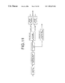
- FIG. 11 is a diagram explaining a compression algorithm according to the WTCQ method and the SPIHT method.
- Original image data S representing an original image are wavelet-transformed first.
- Data in each subband after the transform are classified while bit allocation is determined.
- quantization according to a TCQ method is carried out to obtain quantized data RS.
- Coded data are obtained by carrying out entropy coding on the quantized data RS.
- bit-plane binary arithmetic coding is used as the method for the entropy coding.
- bit-plane binary arithmetic coding quantized data are decomposed into a plurality of bit planes, and converted into binary data.
- Binary arithmetic coding is carried out on the data in each bit plane and each output is coded. Meanwhile, in the SPIHT method, multi-valued arithmetic coding is used as the entropy coding. By compressing the original image data S in this manner, efficient coding with a substantially low bit rate can be carried out.
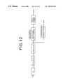
- an arithmetic coding method or a baseline method can be used.
- DCT discrete cosine transform
- quantization is carried out by determining bit allocation.
- arithmetic coding after the quantized data RS have been converted from multi-valued data to binary data, binary arithmetic coding is carried out to obtain coded data.
- the quantized data RS are coded using Huffman coding.
- An object of the present invention is to provide a method and an apparatus for efficient and fast data compression, and a computer-readable recording medium storing a program to cause a computer to execute the data compression method.
- a data compression method of the present invention is a data compression method of obtaining compressed coded data by quantization of original data to obtain quantized data followed by coding and compression of the quantized data.
- the data compression method of the present invention comprises the steps of:
- the second coding method it is preferable for the second coding method to be different between the data having the representative value and each set of the classified data.
- the quantized data it is preferable for the quantized data to be obtained by carrying out wavelet transform on the original data followed by quantization thereof. It is also preferable for the quantized data to be obtained by carrying out DCT on the original data followed by quantization thereof.
- quantization and coding is carried out on wavelet-transformed data in each subband.
- the data having the representative value is 0 data representing the value 0 of the quantized data
- the classified data is preferable for the data having the representative value to be non-zero data representing non-zero values of the quantized data.
- the “value representing the quantized data” herein referred to means various kinds of values such as an average of the data values, a mode in the quantized data, and the value 0.
- various kinds of methods can be used as a method of classifying the quantized data into the data having the representative value and the data other than those.
- the quantized data may be classified simply according to the representative value and non-representative values.
- the data may be classified into the data having the representative value and data having values smaller and larger than the representative value, or into the data having the representative and data having values whose absolute differences from the representative value are smaller and larger than a threshold value.
- the “classification information data” have a value corresponding to the number of classification classes. For example, when the quantized data are classified into 2 classes, namely the data having the representative value and the data having values other than that, the classification information data are binary. When the quantized data are classified into the data having the representative value and data having the values below and above the representative value, the classification information data are 3-valued.
- the phrase stating that the coding method “is different between the data having the representative value and each set of the classified data” means the case where the data having the representative value and the classified data have different coding methods, as well as the case where each set of classified data has a different coding method when a plurality of classified data sets exist.
- any one of Huffman coding, run length coding, B1 coding, B2 coding, Wyle coding, Golomb coding, Golomb-Rice coding, and binary arithmetic coding can be adopted.
- any one of Huffman coding, universal coding, and multi-valued arithmetic coding can be used.
- the coded data if the amount of the coded data is larger than a predetermined information amount determined based on the original data, it is preferable for the coded data to be obtained by coding the classified data according to a third coding method, out of the classification information data and/or the data having the representative value and the classified data.
- the third coding method prefferably be any one of Huffman coding, arithmetic coding, and PCM (Pulse Code Modulation) without any coding.
- the amount of the original data may be used. It is preferable for the predetermined information amount to be an information amount smaller than the amount of the original data and enabling reduction in an information amount when at least the classified data out of the classification information data and/or the data having the representative value and the classified data are coded according to the third coding method.
- a data compression apparatus of the present invention is a data compression apparatus for obtaining compressed coded data by quantization of original data to obtain quantized data followed by coding and compression of the quantized data.
- the data compression apparatus comprises:
- the second coding method carried out by the second coding means prefferably to be different for the data having the representative value and each set of the classified data.
- the data compression apparatus of the present invention prefferably comprises wavelet transform means for obtaining the quantized data by carrying out wavelet transform on the original data followed by quantization thereof, or DCT means for obtaining the quantized data by carrying out DCT on the original data followed by quantization thereof.
- the classification means to classify the quantized data by letting the data having the representative value be 0 data representing the value of 0 of the quantized data and letting the classified data be non-zero data representing non-zero values of the quantized data.
- the data compression apparatus of the present invention to further comprise:
- the processing carried out in the above-described data compression method may be provided in the form of a computer-readable recording medium storing a program to cause a computer to execute the method.
- the quantized data obtained by quantization of the original data are classified into the data having the representative value, the classified data, and the classification information data showing a classification result according to the data values.
- the classification information data are data having a comparatively small information amount, such as binary data or 3-valued data, although the amount depends on the classification. Therefore, coding by a simple coding method can be carried out at a high compression rate and with a light computational load.
- the data having the representative value are data containing only one value. Therefore, coding can be carried out with a small amount of computation and at a comparatively high compression rate.
- the classified data other than the data having the representative value are multi-valued. However, since the representative value have been eliminated, the ratio of these data to the total quantized data is comparatively low.
- the computational load therefor is lighter than the conventional compression algorithm described above, and the data having the representative value and the classification information data can be compressed at a high compression rate with a light computational load. In this manner, the original data can be compressed fast and efficiently, at a high compression rate.
- the classification information data have a comparatively small information amount, such as binary data and 3-valued data
- the classification information data can be compressed fast and efficiently by any one of the Huffman coding, run length coding, B1/B2 coding, Wyle coding, Golomb coding, Golomb-Rice coding, and binary arithmetic coding, which are all comparatively simple operations.
- the multi-valued data in the classified data occupies a small portion of the entire quantized data. Therefore, efficient coding can be carried out by using any one of the Huffman coding, universal coding, and multi-valued arithmetic coding which enable high compression rate coding although computation therefor is complex.
- the original data can be compressed at a high compression rate.
- the original data represents a background image with plain signal values
- only either the data having the representative value or the classified data have information if the original data are quantized and classified into the data having the representative value and the classified data. Therefore, the amount of classification information data is large and the amount of the coded data may become larger than the amount of the original data.
- the information amount of the coded data is compared with the predetermined information amount determined based on the original data, and when the former is larger than the latter, at least the classified data are coded out of the classification information data and/or the data having the representative value and the classified data, according to the third coding method.
- FIG. 1 is a schematic block diagram showing a configuration of a data compression apparatus according to a first embodiment of the present invention
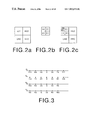
- FIGS. 2 a , 2 b and 2 c are diagrams for explaining wavelet transform
- FIG. 3 is a diagram showing scalar quantizers
- FIG. 4 is a diagram showing sum sets of 2 scalar quantizers
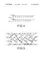
- FIG. 5 is a 4-state trellis diagram
- FIG. 6 is a flow chart showing processing carried out by the first embodiment
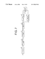
- FIG. 7 is a schematic block diagram showing a configuration of a data compression apparatus according to a second embodiment of the present invention.
- FIG. 8 is a schematic block diagram showing a configuration of a data compression apparatus according to a third embodiment of the present invention.
- FIG. 9 is a flow chart showing processing carried out by data compression apparatus according to the third embodiment.
- FIG. 10 is a schematic block diagram showing a configuration of a data compression apparatus according to a fourth embodiment of the present invention.
- FIG. 11 is a schematic block diagram showing a configuration of a conventional data compression apparatus.
- FIG. 12 is a schematic block diagram showing a configuration of another conventional data compression apparatus.
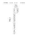
- FIG. 1 is a schematic block diagram showing a configuration of a data compression apparatus according to a first embodiment of the present invention.
- the data compression apparatus according to the first embodiment comprises wavelet transform means 1 for obtaining wavelet-transformed data WS in each subband at each resolution by carrying out wavelet transform on original image data S, classification and bit allocation means 2 for classifying the wavelet-transformed data WS and for determining bit allocation for each class, quantization means 3 for obtaining quantized data RS by quantizing the wavelet-transformed data WS according to the bit allocation determined by the classification and bit allocation means 2 , classification means 4 for obtaining 0 data S 0 , non-zero data NS and classification information data B representing a classification result through classification of the quantized data RS, first coding means 5 for coding the classification information B according to a first coding method, second coding means 6 for coding the non-zero data NS B according to a second coding method, and recording means 7 for recording coded data F resulting from the coding
- the wavelet transform means 1 carries out wavelet transform on the original image data S as follows. As shown in FIG. 2( a ), the original image data S are subjected to wavelet transform and decomposed into 4 sets of data at a plurality of resolutions, namely LL 1 , HL 0 , LH 0 , and HH 0 .
- the data LL 1 represents an image whose width and height are 1 ⁇ 2 of those of the original image
- the data HL 0 , LH 0 and HH 0 respectively represent images of a vertical edge component, a horizontal edge component, and a diagonal edge component. As shown in FIG.
- the data LL 2 represents an image whose width and height are 1 ⁇ 2 of those of the data LL 1
- the data HL 1 , LH 1 and HH 1 represent images of vertical, horizontal and diagonal edge components of the data LL 1 respectively.
- the wavelet transform is repeated a desired number of times on data LL obtained at each wavelet transform, and data at multiple resolutions are obtained thereby.
- data at 3 resolutions can be obtained.
- data at each resolution that is, data in each subband, are all called wavelet-transformed data WS.
- the classification and bit allocation means 2 determines the classification and bit allocation of the wavelet-transformed data WS in the following manner.
- data LL 2 data LL 2
- square error of the data values is calculated for example, and the bit allocation is determined based on the magnitude of the square error. For example, when the square error is large, a large number of bits are allocated for data saving. When the square error is small, a small number of bits are allocated, since missing data are allowed to some degree.
- the quantization means 3 carries out quantization of the wavelet-transformed data WS according to a TCQ (Trellis Coded Quantization), based on the bit allocation determined by the classification and bit allocation means 2 .
- the TCQ method is based on the TCM (Trellis Coded Modulation) developed in the field of signal communication and audio coding, and has been generated by extending this TCM method for image coding.
- the TCQ method can be considered theoretically to have the same meaning as infinite-length vector quantization. From the viewpoint of the rate-distortion theory, an S/N ratio can be improved by several dB's compared with conventional scalar quantization.
- the TCQ method is one of vector quantization methods.
- the same number of quantized values (q 1 , q 2 , . . . qn) are output.
- the quantized values are determined by using the Viterbi algorithm for searching for a path along which a total of quantization errors becomes minimal for the input vector.
- the Viterbi algorithm is applied by letting a mean square of each quantization error be the cost of the path.
- sets of a plurality of quantization representative values are defined, and the quantization representative value sets are used properly depending on a state.
- quantization can be carried out easily by normally using quantization representative values of 16 points.
- 2 sets of quantization representative values for example, Q 1 and Q 2 ) for 16 points are used, and which set of the quantization representative values is used is defined depending on the state, such as Q 1 for a state S 0 , and Q 2 for a state S 1 .
- State transition rules which are common for both quantization and inverse quantization are defined in advance. Quantization progresses while the state transits every time quantization is carried out on one pixel.
- FIG. 3 shows 4 scalar quantizers D 0 to D 3
- FIG. 4 shows sum-sets (sum-set quantizer) of 2 scalar quantizers.
- FIG. 5 shows a 4-state trellis diagram.
- ⁇ is a quantization step size determined by the quantization bit allocation, and assumed to be 0.5 in this embodiment.
- FIG. 5 shows, as state transitions, how an optimal quantizer is selected when the signal having the 5 elements is quantized at one time.
- the transition states are shown by the selected quantizers. In other words, the state wherein the sum-set quantizer D 0 &D 2 has been selected is shown as “state D 0 &D 2 ”. The method of quantization will be explained below.
- MSE mean square errors
- a subsequent quantizer is D 0 (the state shifts to D 0 &D 2 ), or D 2 (the state shifts to D 1 &D 3 ).
- a subsequent quantizer is D 2 (the state shifts to D 0 &D 2 ), or D 0 (the state shifts to D 1 &D 3 ).
- a subsequent quantizer is D 1 (the state shifts to D 2 &D 0 ), or D 3 (the state shifts to D 3 &D 1 ).
- a subsequent quantizer is D 3 (the state shifts to D 2 &D 0 ) or D 1 (the state shifts to D 3 &D 1 ).
- D 3 the state shifts to D 2 &D 0
- D 1 the state shifts to D 3 &D 1
- the subsequent quantizer D 0 corresponds to the state D 0 &D 2
- D 2 corresponds to the state D 1 &D 3
- the subsequent quantizer D 2 corresponds to the state D 0 &D 2
- D 0 corresponds to D 1 &D 3 .
- the subsequent quantizer D 1 corresponds to D 2 &D 0 while D 3 corresponds to D 3 &D 1 .
- the subsequent quantizer D 3 corresponds to the state D 2 &D 0
- D 1 corresponds to the state D 3 &D 1 .
- a restraint length of the trellis transition branches in the trellis diagram corresponds to the number of elements of the signal (in this embodiment, the restraint length is 5, since the number of the elements is 5), and MSE is calculated as the cost in all combinations of the trellis transitions.
- the path along which the sum of the cost becomes minimal is selected, and the quantizers are selected by the path to carry out quantization.
- the cost is basically calculated for all paths. However, when the cumulative cost of a path being calculated exceeds the minimum cost of another path having been calculated, the cost calculation is interrupted and the cost of a subsequent path is then calculated, for example. In this manner, an operation speed is increased. In FIG. 5 , the cost at all paths are shown.
- the index of the quantizers is defined as shown in FIG. 4 .
- the index is output instead of the quantized values.
- the information indicating the initial state is expressed by 3 bits.
- the inverse quantization is carried out on the elements, staring from the first value of the index.
- the index is (1, ⁇ 3, 3, 0, ⁇ 3)
- the quantizer D 2 is selected according to the trellis transition rule shown in FIG. 5 . Therefore, A of the quantizer D 2 , that is, 0.5 is obtained.
- the quantizer D 2 is selected, and the value ⁇ 6 ⁇ of the quantizer D 2 , that is, ⁇ 3 is found.
- the quantizer D 3 is selected, and the value 6 ⁇ of the quantizer D 3 , that is, 3 is found.
- the quantizer D 1 is selected, and the value 0 of the quantizer D 1 is found.
- the classification means 4 classifies the quantized data RS according to their data values. At this time, the quantized data RS are classified into the data having the representative value and data having values other than that. For example, in this embodiment, 0 is the representative value for the quantized data RS, and the quantized data RS are classified into 2 classes, namely 0 data S 0 and non-zero data NS. If quantization is carried out after the wavelet transform on the original image data S, the ratio of 0-values to the quantized data RS becomes substantially large. For example, if 0.5 bit/pixel compression (10-bit original image data S are compressed to 1/20) is carried out, the rate of the non-zero data NS to the entire data is approximately 13%.
- the quantized data RS are classified into the 0 data S 0 , the non-zero data NS, and the classification information data B representing information regarding this classification.
- the classification information data B is binary data representing the result of classification of the quantized data into the 0 data and the non-zero data.
- the first coding means 5 is for coding the classification information data B and any one of the Huffman coding, run length coding, B1 coding, B2 coding, Wyle coding, Golomb coding, Golomb-Rice coding, and binary arithmetic coding, all of which are comparatively simple operations, is adopted as the coding method.
- Huffman coding is widely known as a method of generating instantaneously decodable compact code.
- Huffman coding when a probability distribution of information source alphabets is provided, instantaneously decodable compact code can always be obtained by using a simple algorithm. Therefore, this is a extremely effective coding algorithm.
- the run length coding is a coding method wherein length of symbols “0” and “1” are coded or a specific pattern considering an interval of appearance probability of “0” and “1” is coded when the symbol “0” in binary information has a higher probability which is close to 1 or when long runs of “0” or “1” appear alternately.
- B1 and B2 coding is one of the run length coding methods and the detail thereof is described in “T. Fukinuke, Digital Image Signal Processing (in Japanese), Nikkan Kogyo Shinbun Co, May 25, 1981”.
- Wyle coding is one of the run length coding methods.
- Wyle coding has been proposed based on a principle that an average code length is shortened by measuring a probability distribution of a run of each symbol represented by a sequence of “0” and “1” and then by assigning a short code for a run having a high probability and a long code for a run having a low probability.
- Golomb coding has been known as code of an efficient entropy coding for a geometric distribution information source.
- the code cannot necessarily be a compact code.
- This method is called Golomb-Rice method when the degree is a power of 2, and coding and decoding by a simple configuration becomes possible.
- the arithmetic coding uses uniquely decodable compact code.
- This coding method has extreme generality including the Huffman coding. Coding and decoding can be executed by carrying out arithmetic operations, and a symbol in a information source symbol sequence is coded by executing an algorithm.
- the arithmetic coding can be considered as a process of sequentially dividing a unit interval (0, 1) into partial intervals satisfying the following 2 conditions:
- Each code word is a sum of appearance probability (cumulative probability) of proceeding information source symbol.
- the binary arithmetic coding is appropriate for binary data.
- the second coding means 6 is for coding the non-zero data NS.
- any one of the Huffman coding, universal coding, and multi-valued arithmetic coding can be used. These coding methods are efficient, that is, they enable data coding at a high compression rate, although the operation therefor is complex.
- the universal coding is a block coding method asymptotically optimal for an information source whose parameter is unknown.
- the universal coding satisfies the following 2 conditions:
- Coding is carried out depending only on a statistic amount of a measured information source message block, not depending on a past or future block. In other words, coding is carried out memorylessly on each block.
- the multi-valued arithmetic coding is appropriate for multi-valued data.
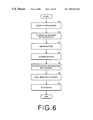
- FIG. 6 is a flow chart showing processing carried out by the data compression apparatus according to the first embodiment.
- the wavelet transform means 1 carries out wavelet transform on the original image data S to obtain the wavelet-transformed data WS, as has been described above (step S 1 ).
- the classification and bit allocation means 2 then classifies the wavelet-transformed data WS and determines the bit allocation of each class (step S 2 ).
- the quantization means 3 quantizes the wavelet-transformed data WS in each class based on the determined bit allocation.
- the quantized data RS are obtained in this manner (step S 3 ).
- the quantized data RS are classified into the 0 data S 0 and the non-zero data NS by the classification means 4 , and the classification information data B indicating classification of the 0 and non-zero data are obtained (step S 4 ).
- the classification information data B are coded by the first coding means 5 according to any one of the above-described Huffman coding, run length coding, B1 coding, B2 coding, Wyle coding, Golomb coding, Golomb-Rice coding, and binary arithmetic coding (step S 5 ).
- the non-zero data NS are coded by the second coding means 6 according to any one of the above-described Huffman coding, universal coding, and multi-valued arithmetic coding (step S 6 ).
- the processing at the steps S 5 and S 6 may be exchanged, or carried out in parallel.
- the coded classification information data B and the non-zero data NS are recorded as coded data F in a recording medium by the recording means 7 (step S 7 ), and the processing ends.
- the classification information data B and the non-zero data NS are obtained by decoding the coded classification information data B and the non-zero value data NS both included in the coded data F, according to decoding methods corresponding to the coding methods.
- the quantized data RS are obtained by finding the 0 data S 0 based on the classification information B and the non-zero data NS.
- the quantized data RS are inversely quantized and the wavelet-transformed data WS are obtained. By carrying out inverse wavelet transform on the wavelet-transformed data WS, the original image data S are finally obtained.
- the classification information data B obtained in the first embodiment are binary data, and have a comparatively small data size. Therefore, coding having a light computational load and at a high compression rate can be carried out by the first coding means 5 employing the simple coding method.
- the 0 data S 0 inherently have no information. Therefore, decoding can be carried out without coding the 0 data if only the classification information regarding the classification of the 0 data and the non-zero data is available.
- the non-zero data NS are multi-valued, the rate thereof to the total quantized data RS is only approximately 13%. Therefore, a computational load can be reduced even when the coding method having high efficiency but computational complexity is employed by the second coding means 6 .
- the computational load is comparatively lighter than the conventional compression algorithm described above, and the classification information data B can be compressed at a high compression rate, with a small computational load. In this manner, the original image data S can be compressed fast and at a high compression rate.
- the quantized data RS are classified into the 0 data S 0 and the non-zero data NS, classification thereof is easy. Furthermore, compression of the 0 data S 0 is not necessary, which leads to a lighter computational load and fast compression of the original image data S.
- FIG. 7 shows a schematic block diagram of a configuration of a data compression apparatus according to the second embodiment of the present invention.
- the data compression apparatus comprises DCT means 10 for transforming the original image data S according to discrete cosine transform (DCT), not according to the wavelet transform, and the data classification in the case of the wavelet transform is not carried out.
- DCT discrete cosine transform
- bit allocation, and quantization are a quantization method standardized according to the JPEG format.
- the original image data S can be coded fast and efficiently, as in the first embodiment.
- the original image data S can be compressed at a high compression rate.
- the coded data F may have a larger amount of information than the original image data S, since the amount of the classification information B is large due to the quantized data having been classified into the non-zero data NS only.
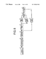
- FIG. 8 is a schematic block diagram showing a configuration of a data compression apparatus according to the third embodiment of the present invention.
- the data compression apparatus comprises comparison means 12 for comparing the information amount between coded data F 1 in each subband in the coded data F obtained by the first embodiment and the wavelet-transformed data WS, and third coding means for obtaining coded data F 2 by coding the quantized data RS according to a third coding method when the information amount of the coded data F 1 in each subband has been judged by the comparison means 12 to be larger than that of the wavelet-transformed data WS.
- the comparison means 12 compares the information amount between the coded data F 1 in each subband and the wavelet-transformed data WS.
- the amount of the wavelet-transformed data WS is the length of the signal sequence in the quantized data RS ⁇ 16 bits.
- the third coding means 13 carries out coding on the quantized data RS according to the third coding method and obtains the coded data F 2 .
- the coded data F 1 have smaller amount of data than the wavelet-trans formed data WS, the coded data F 1 are input to the recording means 7 as the coded data F.
- the coding method employed by the third coding means 13 a method which enables efficient data coding at a high compression rate, such as Huffman coding and multi-valued arithmetic coding, can be used, although the operation therefor is complex.
- the PCM method which carries out no coding may be adopted.
- the coding method used by the third coding means is also described in the above-cited reference by Kasahara et al.
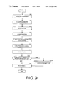
- FIG. 9 is a flow chart showing the operation carried out by the third embodiment.
- processing from step S 11 through step S 16 is the same as the processing from the step S 1 through the step S 6 in the flow chart shown in FIG. 6 . Therefore, explanation thereof is not repeated.
- the non-zero data NS are coded according to the second coding method and the coded data F 1 in each subband are obtained.
- the coded data F 1 are then input to the comparison means 12 and compared with the wavelet-transformed data WS (step S 17 ).
- step S 18 Whether or not the coded data F 1 in each subband have a larger information amount than the wavelet-transformed data WS is judged (step S 18 ). If the coded data F 1 in each subband have a larger information amount than the wavelet-transformed data WS, the third coding means 13 carries out coding on the quantized data RS in the subband according to the third coding method and the coded data F 2 are obtained (step S 19 ). When the step S 18 is denied, the coded data F 1 are the final coded data F in the subband.
- step S 19 For each subband, the processing from the step S 17 to the step S 19 is carried out and the coded data F 1 or F 2 in each subband are recorded as the final coded data F in a recording medium by the recording means 7 (step S 20 ), and the processing ends.
- the amount of information of the coded data F 1 in a subband is compared with that of the wavelet transformed data WS.
- the quantized data RS in the subband are coded according to the third coding method such as the Huffman coding. Therefore, the information amount of the coded data F obtained finally does not exceed the information amount of the wavelet-transformed data WS. In this manner, efficient coding of the original image data S can be carried out.
- processing which is a reversal of the flow chart shown in FIG. 9 is carried out.
- the coding method of the coded data F 1 and F 2 in each subband included in the coded data F is judged, and pairs of the non-zero data NS and the classification information B, as well as the quantized data RS are obtained by decoding the coded data F 1 and F 2 according to a decoding method corresponding to the coding method.
- the quantized data RS are obtained by finding the 0 data S 0 based thereon.
- the quantized data RS are inversely quantized and the wavelet-transformed data WS are obtained. By carrying out inverse wavelet transform on the wavelet-transformed data WS, the original image data S are finally obtained.
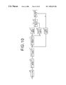
- FIG. 10 is a schematic block diagram showing a configuration of a data compression apparatus according to the fourth embodiment.
- the fourth embodiment differs from the third embodiment in the following points.
- the data compression apparatus comprises DCT means 10 for transforming the original image data S according to discrete cosine transform (DCT) method, not according to the wavelet transform method.
- DCT discrete cosine transform
- bit allocation, and quantization are a quantization method standardized according to the JPEG format, as in the second embodiment.
- the information amount of the coded data F obtained by the second embodiment is compared with that of the original image data S, and when the former is larger than the latter, coded data F 3 are obtained by carrying out coding on the quantized data RS by the third coding means 13 according to the third coding method.
- the coded data F 3 are recorded as the final coded data F in a recording medium by the recording means 7 .
- the information amount of the coded data F is compared with that of the original image data S, as in the third embodiment.
- the quantized data RS are coded according to the third coding method. In this manner, coding of the original image data S can be carried out fast and efficiently as in the third embodiment.
- the quantized data RS are classified into the 0 data S 0 and the non-zero data NS, using 0 as the representative value.
- the quantized data may be classified into 3 classes, namely the 0 data, data having values larger than 0 and smaller than a threshold value, and data having values equal to or larger than the threshold value.
- the same coding as in the above embodiments is carried out.
- coding emphasizing efficiency is carried out thereon, since these values have a statistically small probability of appearance.
- the representative value 0 is not the only example, and an average of the quantized data RS may be used.
- classification may be carried out according to various classification rules, such as data having the average value and the other values, the average and values lower than the average and higher than the average, and data whose absolute differences from the average are smaller than a threshold value and equal to or larger than the threshold value.
- image data have been coded according to the data compression method and apparatus of the present invention.
- various kinds of data such as audio data and animation data can be coded by the data compression method and apparatus of the present invention.
- the amount of information of the coded data F 1 has been compared with that of the wavelet-transformed data WS or the original image data S.
- the amount of information of the coded data F 1 may be compared with a predetermined threshold value which is smaller than the information amount of the wavelet-transformed data WS or the original image data S but enables reduction in the information amount when the quantized data RS are coded according to the third coding method.
Landscapes
- Engineering & Computer Science (AREA)
- Multimedia (AREA)
- Signal Processing (AREA)
- Compression Of Band Width Or Redundancy In Fax (AREA)
- Compression Or Coding Systems Of Tv Signals (AREA)
Abstract
Description
-
- classifying the quantized data into data having a value representing the quantized data and at least one set of classified data representing a data value other than the representative value while obtaining classification information data regarding this classification;
- coding the classification information data according to a first coding method; and
- obtaining the coded data by coding at least the classified data out of the classified data and the data having the representative value, according to a second coding method.
-
- classification means for classifying the quantized data into data having a representative value representing the quantized data and at least one set of classified data having a data value other than the representative value and for obtaining classification information data representing this classification;
- first coding means for coding the classification information data by using a first coding method; and
- second coding means for coding at least the classified data according to a second coding method, out of the data having the representative value and the classified data.
-
- judging means for judging whether or not the amount of the coded data is larger than a predetermined information amount determined based on the original data; and
- third coding means for obtaining the coded data by coding at least the classified data according to a third compression method out of the classification information data and/or the data having the representative value and the classified data, in the case where the judging means has judged the amount of the coded data to be larger than the predetermined information amount.
(0.5−Δ)2+(−3−(−6Δ))2+(3−6Δ)2+(0.25−0)2+(−2.5−(−5Δ))2=0.0625
Claims (30)
Applications Claiming Priority (2)
| Application Number | Priority Date | Filing Date | Title |
|---|---|---|---|
| JP20250198 | 1998-07-17 | ||
| JP35015998 | 1998-12-09 |
Publications (1)
| Publication Number | Publication Date |
|---|---|
| US7003171B1 true US7003171B1 (en) | 2006-02-21 |
Family
ID=35810735
Family Applications (1)
| Application Number | Title | Priority Date | Filing Date |
|---|---|---|---|
| US09/356,505 Expired - Lifetime US7003171B1 (en) | 1998-07-17 | 1999-07-19 | Method, apparatus and recording medium for data compression |
Country Status (1)
| Country | Link |
|---|---|
| US (1) | US7003171B1 (en) |
Cited By (12)
| Publication number | Priority date | Publication date | Assignee | Title |
|---|---|---|---|---|
| US20060071827A1 (en) * | 2003-04-17 | 2006-04-06 | Lynch William C | Multiple technique entropy coding system and method |
| US20070031051A1 (en) * | 2005-08-03 | 2007-02-08 | Samsung Electronics Co., Ltd. | Image encoding apparatus and method, and image decoding apparatus and method |
| US20070233473A1 (en) * | 2006-04-04 | 2007-10-04 | Lee Kang Eun | Multi-path trellis coded quantization method and multi-path coded quantizer using the same |
| US20080174783A1 (en) * | 2006-12-15 | 2008-07-24 | Mater Michael J | System and method of interferometric imaging using a digital micromirror device |
| US20090080788A1 (en) * | 2003-04-17 | 2009-03-26 | Droplet Technology, Inc. | Multiple Technique Entropy Coding System And Method |
| EP2059049A1 (en) * | 2007-11-07 | 2009-05-13 | British Telecmmunications public limited campany | Video coding |
| US20100174814A1 (en) * | 2009-01-08 | 2010-07-08 | Alcatel-Lucent | Connectivity, adjacencies and adaptation functions |
| US10212417B2 (en) | 2001-02-13 | 2019-02-19 | Realtime Adaptive Streaming Llc | Asymmetric data decompression systems |
| US10284225B2 (en) | 2000-10-03 | 2019-05-07 | Realtime Data, Llc | Systems and methods for data compression |
| US10827175B2 (en) | 2014-07-28 | 2020-11-03 | Samsung Electronics Co., Ltd. | Signal encoding method and apparatus and signal decoding method and apparatus |
| CN114629501A (en) * | 2022-03-16 | 2022-06-14 | 重庆邮电大学 | Edge data classification compression method of machining process state information |
| US11451840B2 (en) * | 2018-06-18 | 2022-09-20 | Qualcomm Incorporated | Trellis coded quantization coefficient coding |
-
1999
- 1999-07-19 US US09/356,505 patent/US7003171B1/en not_active Expired - Lifetime
Non-Patent Citations (4)
| Title |
|---|
| IEEE Transactions of Image Processing, vol. 4, Jun. 1995, pp. 725-733, "Image Coding Using Wavelet Transforms and Entropy-Constrained Trellis-Coded Quantization". |
| IEEE Transactions on Circuits and Systems for Video Technology, vol. 6, Jun. 1996, pp. 243-250, "A New Fast and Efficient Image Codec Based on Set Partitioning in Hierarchical Trees". |
| Nikkan Kogyo Shimbun Co., May 25, 1981, "Digital Image Signal Processing", Fukinuke, T. |
| Shokodo Co., Feb. 25, 1992, "Digital Communication Systems", Kasahara et al. |
Cited By (23)
| Publication number | Priority date | Publication date | Assignee | Title |
|---|---|---|---|---|
| US10284225B2 (en) | 2000-10-03 | 2019-05-07 | Realtime Data, Llc | Systems and methods for data compression |
| US10212417B2 (en) | 2001-02-13 | 2019-02-19 | Realtime Adaptive Streaming Llc | Asymmetric data decompression systems |
| US7436329B2 (en) * | 2003-04-17 | 2008-10-14 | Droplet Technology, Inc. | Multiple technique entropy coding system and method |
| US20090080788A1 (en) * | 2003-04-17 | 2009-03-26 | Droplet Technology, Inc. | Multiple Technique Entropy Coding System And Method |
| US20060071827A1 (en) * | 2003-04-17 | 2006-04-06 | Lynch William C | Multiple technique entropy coding system and method |
| US20070031051A1 (en) * | 2005-08-03 | 2007-02-08 | Samsung Electronics Co., Ltd. | Image encoding apparatus and method, and image decoding apparatus and method |
| US7747092B2 (en) * | 2005-08-03 | 2010-06-29 | Samsung Electronics Co., Ltd. | Image encoding apparatus and method, and image decoding apparatus and method |
| US8706481B2 (en) | 2006-04-04 | 2014-04-22 | Samsung Electronics Co., Ltd. | Multi-path trellis coded quantization method and multi-path coded quantizer using the same |
| US20070233473A1 (en) * | 2006-04-04 | 2007-10-04 | Lee Kang Eun | Multi-path trellis coded quantization method and multi-path coded quantizer using the same |
| WO2007114555A1 (en) * | 2006-04-04 | 2007-10-11 | Samsung Electronics Co., Ltd. | Multi-path trellis coded quantization method and multi-path coded quantizer using the same |
| US20080174783A1 (en) * | 2006-12-15 | 2008-07-24 | Mater Michael J | System and method of interferometric imaging using a digital micromirror device |
| US8774275B2 (en) | 2007-11-07 | 2014-07-08 | British Telecommunications Public Limited Company | Video coding |
| US20100246677A1 (en) * | 2007-11-07 | 2010-09-30 | Michael Erling Nilsson | Video coding |
| WO2009060178A1 (en) * | 2007-11-07 | 2009-05-14 | British Telecommunications Public Limited Company | Video coding |
| EP2059049A1 (en) * | 2007-11-07 | 2009-05-13 | British Telecmmunications public limited campany | Video coding |
| US8495245B2 (en) * | 2009-01-08 | 2013-07-23 | Alcatel Lucent | Connectivity, adjacencies and adaptation functions |
| US20130227169A1 (en) * | 2009-01-08 | 2013-08-29 | Peter Busschbach | Connectivity, adjacencies and adaptation functions |
| US20100174814A1 (en) * | 2009-01-08 | 2010-07-08 | Alcatel-Lucent | Connectivity, adjacencies and adaptation functions |
| US9049187B2 (en) * | 2009-01-08 | 2015-06-02 | Alcatel Lucent | Connectivity, adjacencies and adaptation functions |
| US10827175B2 (en) | 2014-07-28 | 2020-11-03 | Samsung Electronics Co., Ltd. | Signal encoding method and apparatus and signal decoding method and apparatus |
| US11616954B2 (en) | 2014-07-28 | 2023-03-28 | Samsung Electronics Co., Ltd. | Signal encoding method and apparatus and signal decoding method and apparatus |
| US11451840B2 (en) * | 2018-06-18 | 2022-09-20 | Qualcomm Incorporated | Trellis coded quantization coefficient coding |
| CN114629501A (en) * | 2022-03-16 | 2022-06-14 | 重庆邮电大学 | Edge data classification compression method of machining process state information |
Similar Documents
| Publication | Publication Date | Title |
|---|---|---|
| US6233359B1 (en) | File size bounded JPEG transcoder (FSBJT) | |
| EP0680643B1 (en) | Apparatus and method for compressing information | |
| US6567562B1 (en) | Encoding apparatus and method | |
| US5764807A (en) | Data compression using set partitioning in hierarchical trees | |
| US5959560A (en) | Data compression via alphabet partitioning and group partitioning | |
| US7003171B1 (en) | Method, apparatus and recording medium for data compression | |
| US20060222249A1 (en) | Image-comparing apparatus, image-comparing method, image-retrieving apparatus and image-retrieving method | |
| US6885320B2 (en) | Apparatus and method for selecting length of variable length coding bit stream using neural network | |
| US7133567B2 (en) | Image coding apparatus and image coding method | |
| US8005306B2 (en) | Decoding apparatus, inverse quantization method, and computer readable medium | |
| Algazi et al. | Analysis-based coding of image transform and subband coefficients | |
| US8116373B2 (en) | Context-sensitive encoding and decoding of a video data stream | |
| Rahman et al. | Histogram alternation based digital image compression using base-2 coding | |
| Tagliasacchi et al. | Transform coder identification based on quantization footprints and lattice theory | |
| JP3808241B2 (en) | Data compression method and apparatus, and recording medium | |
| JPH08331563A (en) | Image compressing method using ripple conversion | |
| Lalitha et al. | Image compression of MRI image using planar coding | |
| JP2006033161A (en) | Encoder | |
| Kanefsky et al. | Predictive source coding techniques using maximum likelihood prediction for compression of digitized images | |
| Shapiro | Image coding using the embedded zerotree wavelet algorithm | |
| JP2001223593A (en) | Data coding method and system, and recording medium | |
| JP3359214B2 (en) | Multi-level image coding device | |
| US7720300B1 (en) | System and method for effectively performing an adaptive quantization procedure | |
| JP2000184207A (en) | Data compression method, system and recoding medium | |
| Liu et al. | Context formation by mutual information maximization |
Legal Events
| Date | Code | Title | Description |
|---|---|---|---|
| AS | Assignment |
Owner name: FUJI PHOTO FILM CO., LTD., JAPAN Free format text: ASSIGNMENT OF ASSIGNORS INTEREST;ASSIGNOR:TAKEO, HIDEYA;REEL/FRAME:010117/0504 Effective date: 19990713 |
|
| STCF | Information on status: patent grant |
Free format text: PATENTED CASE |
|
| AS | Assignment |
Owner name: FUJIFILM CORPORATION, JAPAN Free format text: ASSIGNMENT OF ASSIGNORS INTEREST;ASSIGNOR:FUJIFILM HOLDINGS CORPORATION (FORMERLY FUJI PHOTO FILM CO., LTD.);REEL/FRAME:018904/0001 Effective date: 20070130 Owner name: FUJIFILM CORPORATION,JAPAN Free format text: ASSIGNMENT OF ASSIGNORS INTEREST;ASSIGNOR:FUJIFILM HOLDINGS CORPORATION (FORMERLY FUJI PHOTO FILM CO., LTD.);REEL/FRAME:018904/0001 Effective date: 20070130 |
|
| FPAY | Fee payment |
Year of fee payment: 4 |
|
| FEPP | Fee payment procedure |
Free format text: PAYOR NUMBER ASSIGNED (ORIGINAL EVENT CODE: ASPN); ENTITY STATUS OF PATENT OWNER: LARGE ENTITY |
|
| FPAY | Fee payment |
Year of fee payment: 8 |
|
| FPAY | Fee payment |
Year of fee payment: 12 |