US7002159B2 - Boron coated straw neutron detector - Google Patents
Boron coated straw neutron detector Download PDFInfo
- Publication number
- US7002159B2 US7002159B2 US10/712,692 US71269203A US7002159B2 US 7002159 B2 US7002159 B2 US 7002159B2 US 71269203 A US71269203 A US 71269203A US 7002159 B2 US7002159 B2 US 7002159B2
- Authority
- US
- United States
- Prior art keywords
- straw
- neutron
- article
- tube
- thin
- Prior art date
- Legal status (The legal status is an assumption and is not a legal conclusion. Google has not performed a legal analysis and makes no representation as to the accuracy of the status listed.)
- Expired - Lifetime, expires
Links
- 239000010902 straw Substances 0.000 title claims abstract description 193
- ZOXJGFHDIHLPTG-UHFFFAOYSA-N Boron Chemical compound [B] ZOXJGFHDIHLPTG-UHFFFAOYSA-N 0.000 title description 10
- 229910052796 boron Inorganic materials 0.000 title description 10
- 238000001514 detection method Methods 0.000 claims abstract description 33
- 238000000576 coating method Methods 0.000 claims abstract description 32
- 239000011248 coating agent Substances 0.000 claims abstract description 31
- 239000007789 gas Substances 0.000 claims description 48
- 239000000463 material Substances 0.000 claims description 43
- 241001589086 Bellapiscis medius Species 0.000 claims description 22
- 238000004519 manufacturing process Methods 0.000 claims description 22
- 230000035945 sensitivity Effects 0.000 claims description 20
- 230000005855 radiation Effects 0.000 claims description 11
- 230000003993 interaction Effects 0.000 claims description 10
- 239000000203 mixture Substances 0.000 claims description 10
- 239000004033 plastic Substances 0.000 claims description 9
- 229920003023 plastic Polymers 0.000 claims description 9
- 230000005251 gamma ray Effects 0.000 claims description 8
- 239000002985 plastic film Substances 0.000 claims description 5
- 229920006255 plastic film Polymers 0.000 claims description 5
- 230000008021 deposition Effects 0.000 claims description 4
- 229910052751 metal Inorganic materials 0.000 claims description 4
- 239000002184 metal Substances 0.000 claims description 4
- UFHFLCQGNIYNRP-UHFFFAOYSA-N Hydrogen Chemical compound [H][H] UFHFLCQGNIYNRP-UHFFFAOYSA-N 0.000 claims description 3
- 239000001257 hydrogen Substances 0.000 claims description 3
- 229910052739 hydrogen Inorganic materials 0.000 claims description 3
- 230000004044 response Effects 0.000 claims description 3
- 239000000853 adhesive Substances 0.000 claims description 2
- 230000001070 adhesive effect Effects 0.000 claims description 2
- 230000003321 amplification Effects 0.000 claims 1
- 238000003199 nucleic acid amplification method Methods 0.000 claims 1
- 239000007795 chemical reaction product Substances 0.000 abstract description 20
- 239000010408 film Substances 0.000 abstract description 16
- 238000006243 chemical reaction Methods 0.000 abstract description 15
- 238000005516 engineering process Methods 0.000 abstract description 6
- 239000010409 thin film Substances 0.000 abstract description 5
- 230000004888 barrier function Effects 0.000 abstract description 2
- 229910052580 B4C Inorganic materials 0.000 description 43
- 239000010410 layer Substances 0.000 description 39
- INAHAJYZKVIDIZ-UHFFFAOYSA-N boron carbide Chemical compound B12B3B4C32B41 INAHAJYZKVIDIZ-UHFFFAOYSA-N 0.000 description 38
- 238000000034 method Methods 0.000 description 31
- 229910052782 aluminium Inorganic materials 0.000 description 14
- XAGFODPZIPBFFR-UHFFFAOYSA-N aluminium Chemical compound [Al] XAGFODPZIPBFFR-UHFFFAOYSA-N 0.000 description 14
- 238000013461 design Methods 0.000 description 12
- 230000008901 benefit Effects 0.000 description 9
- 239000000758 substrate Substances 0.000 description 9
- 238000003491 array Methods 0.000 description 8
- 230000004907 flux Effects 0.000 description 8
- 239000002245 particle Substances 0.000 description 8
- 229920002799 BoPET Polymers 0.000 description 7
- 239000004593 Epoxy Substances 0.000 description 7
- OTMSDBZUPAUEDD-UHFFFAOYSA-N Ethane Chemical compound CC OTMSDBZUPAUEDD-UHFFFAOYSA-N 0.000 description 7
- 238000010276 construction Methods 0.000 description 7
- 238000001956 neutron scattering Methods 0.000 description 7
- RYGMFSIKBFXOCR-UHFFFAOYSA-N Copper Chemical compound [Cu] RYGMFSIKBFXOCR-UHFFFAOYSA-N 0.000 description 6
- 229910052802 copper Inorganic materials 0.000 description 6
- 239000010949 copper Substances 0.000 description 6
- 239000011888 foil Substances 0.000 description 6
- 238000000342 Monte Carlo simulation Methods 0.000 description 5
- 238000013459 approach Methods 0.000 description 5
- 230000008569 process Effects 0.000 description 5
- 239000013077 target material Substances 0.000 description 5
- XKRFYHLGVUSROY-UHFFFAOYSA-N Argon Chemical compound [Ar] XKRFYHLGVUSROY-UHFFFAOYSA-N 0.000 description 4
- 229910001369 Brass Inorganic materials 0.000 description 4
- 241001637516 Polygonia c-album Species 0.000 description 4
- 239000010951 brass Substances 0.000 description 4
- 230000009977 dual effect Effects 0.000 description 4
- 238000003384 imaging method Methods 0.000 description 4
- 239000011159 matrix material Substances 0.000 description 4
- 238000010791 quenching Methods 0.000 description 4
- 238000004804 winding Methods 0.000 description 4
- 229910052786 argon Inorganic materials 0.000 description 3
- 230000001934 delay Effects 0.000 description 3
- 239000011152 fibreglass Substances 0.000 description 3
- 238000005259 measurement Methods 0.000 description 3
- 238000001228 spectrum Methods 0.000 description 3
- 229910001220 stainless steel Inorganic materials 0.000 description 3
- 239000010935 stainless steel Substances 0.000 description 3
- 239000000126 substance Substances 0.000 description 3
- 229920004747 ULTEM® 1000 Polymers 0.000 description 2
- 239000011230 binding agent Substances 0.000 description 2
- 150000001639 boron compounds Chemical class 0.000 description 2
- 150000001875 compounds Chemical class 0.000 description 2
- 238000005520 cutting process Methods 0.000 description 2
- 238000011161 development Methods 0.000 description 2
- 230000000694 effects Effects 0.000 description 2
- 230000005281 excited state Effects 0.000 description 2
- 238000002474 experimental method Methods 0.000 description 2
- 239000012634 fragment Substances 0.000 description 2
- 230000006872 improvement Effects 0.000 description 2
- 229910001416 lithium ion Inorganic materials 0.000 description 2
- 229920000642 polymer Polymers 0.000 description 2
- 239000000047 product Substances 0.000 description 2
- 238000004544 sputter deposition Methods 0.000 description 2
- 229910015239 B3Si Inorganic materials 0.000 description 1
- ZOXJGFHDIHLPTG-BJUDXGSMSA-N Boron-10 Chemical compound [10B] ZOXJGFHDIHLPTG-BJUDXGSMSA-N 0.000 description 1
- 239000004215 Carbon black (E152) Substances 0.000 description 1
- 239000005041 Mylar™ Substances 0.000 description 1
- 229920004738 ULTEM® Polymers 0.000 description 1
- 230000001464 adherent effect Effects 0.000 description 1
- 239000012790 adhesive layer Substances 0.000 description 1
- 230000001668 ameliorated effect Effects 0.000 description 1
- 230000009286 beneficial effect Effects 0.000 description 1
- 230000015572 biosynthetic process Effects 0.000 description 1
- 230000015556 catabolic process Effects 0.000 description 1
- 239000004568 cement Substances 0.000 description 1
- 239000000919 ceramic Substances 0.000 description 1
- 125000003897 citraconoyl group Chemical group C(\C(\C)=C/C(=O)*)(=O)* 0.000 description 1
- 239000011247 coating layer Substances 0.000 description 1
- 239000000470 constituent Substances 0.000 description 1
- 239000000109 continuous material Substances 0.000 description 1
- 230000003247 decreasing effect Effects 0.000 description 1
- 238000006731 degradation reaction Methods 0.000 description 1
- 238000000151 deposition Methods 0.000 description 1
- 238000005137 deposition process Methods 0.000 description 1
- 239000003989 dielectric material Substances 0.000 description 1
- 238000006073 displacement reaction Methods 0.000 description 1
- 238000004980 dosimetry Methods 0.000 description 1
- 238000002651 drug therapy Methods 0.000 description 1
- 125000003700 epoxy group Chemical group 0.000 description 1
- 230000002349 favourable effect Effects 0.000 description 1
- 239000012467 final product Substances 0.000 description 1
- 238000010304 firing Methods 0.000 description 1
- 239000003292 glue Substances 0.000 description 1
- 239000010438 granite Substances 0.000 description 1
- 230000005283 ground state Effects 0.000 description 1
- 229930195733 hydrocarbon Natural products 0.000 description 1
- 150000002430 hydrocarbons Chemical class 0.000 description 1
- 230000001771 impaired effect Effects 0.000 description 1
- 238000009434 installation Methods 0.000 description 1
- 230000010354 integration Effects 0.000 description 1
- 238000011031 large-scale manufacturing process Methods 0.000 description 1
- 239000011133 lead Substances 0.000 description 1
- 239000004973 liquid crystal related substance Substances 0.000 description 1
- 150000002641 lithium Chemical class 0.000 description 1
- 230000033001 locomotion Effects 0.000 description 1
- 238000012423 maintenance Methods 0.000 description 1
- 239000005300 metallic glass Substances 0.000 description 1
- 150000002739 metals Chemical class 0.000 description 1
- 239000000693 micelle Substances 0.000 description 1
- 238000002156 mixing Methods 0.000 description 1
- 238000001683 neutron diffraction Methods 0.000 description 1
- 238000005457 optimization Methods 0.000 description 1
- 230000008520 organization Effects 0.000 description 1
- 229920000647 polyepoxide Polymers 0.000 description 1
- 239000000843 powder Substances 0.000 description 1
- 102000004169 proteins and genes Human genes 0.000 description 1
- 108090000623 proteins and genes Proteins 0.000 description 1
- 239000002994 raw material Substances 0.000 description 1
- 230000009467 reduction Effects 0.000 description 1
- 238000011160 research Methods 0.000 description 1
- 229920006395 saturated elastomer Polymers 0.000 description 1
- 238000000926 separation method Methods 0.000 description 1
- 238000004088 simulation Methods 0.000 description 1
- 239000011343 solid material Substances 0.000 description 1
- 238000007740 vapor deposition Methods 0.000 description 1
Images


Classifications
-
- H—ELECTRICITY
- H01—ELECTRIC ELEMENTS
- H01J—ELECTRIC DISCHARGE TUBES OR DISCHARGE LAMPS
- H01J47/00—Tubes for determining the presence, intensity, density or energy of radiation or particles
- H01J47/12—Neutron detector tubes, e.g. BF3 tubes
- H01J47/1205—Neutron detector tubes, e.g. BF3 tubes using nuclear reactions of the type (n, alpha) in solid materials, e.g. Boron-10 (n,alpha) Lithium-7, Lithium-6 (n, alpha)Hydrogen-3
- H01J47/1222—Proportional counters
-
- G—PHYSICS
- G01—MEASURING; TESTING
- G01T—MEASUREMENT OF NUCLEAR OR X-RADIATION
- G01T1/00—Measuring X-radiation, gamma radiation, corpuscular radiation, or cosmic radiation
- G01T1/16—Measuring radiation intensity
- G01T1/185—Measuring radiation intensity with ionisation chamber arrangements
-
- G—PHYSICS
- G01—MEASURING; TESTING
- G01T—MEASUREMENT OF NUCLEAR OR X-RADIATION
- G01T3/00—Measuring neutron radiation
Definitions
- This invention relates to a thermal neutron detector the most elemental component of which is a 10 B-lined straw tube which can be applied in multiple applications including neutron radiation survey and neutron imaging.
- the detector is also capable of counting gamma radiation alone or simultaneously with neutron counting.
- Neutron scattering is a very valuable technique which is critically important to materials science and structural biology applications. Neutron scattering is an important source of information about the atomic positions, motions, and magnetic properties of solid materials. As a beam of thermal neutrons is directed at a target material some neutrons will interact directly with the atomic nuclei of such material and “bounce” away at various angles related to the atomic arrangements that define the structure of the target material. This behavior is referred to as neutron diffraction, or neutron scattering.
- New facilities for neutron generation at much higher flux such as the Spallation Neutron Source (SNS) facility due for completion at Oak Ridge in 2006, will greatly enhance the capabilities of neutron scattering.
- SNS Spallation Neutron Source
- the benefits offered by superior neutron scattering techniques extend to many fields and include, for example, development of improved drug therapies and materials that are stronger, longer-lasting, and more impact-resistant.
- these higher flux rates must be met with improved neutron scatter detection capabilities; particularly higher count rate capability in large area size detectors, while maintaining practicality.
- the SNS facility will enhance the available thermal neutron flux by at least an order of magnitude above that now achievable at any other neutron science facility.
- This higher neutron beam intensity, together with time of flight energy discrimination provided by pulsed operation of the SNS facility, will facilitate unprecedented capabilities, which will be exploited in more than 18 experiment stations (http://www.sns.gov/).
- the markedly increased deliverable neutron flux imposes extreme rate requirements on the neutron scattering detectors in many of these facilities, which cannot now be met without fundamental detector improvements.
- a neutron detector technology based on 10 B thin film conversion of neutrons and detection of neutron capture reaction products in a counter gas within a thin straw tube detector body is described.
- This neutron scatter detector is based on gas-filled thin wall straw tubes, modified for the conversion of neutrons in a very thin coating, or layer, of 10 B, applied for example as a sputter-coated film of 10 B 4 C, that lines the interior, or inside of the straw tube surface; and the subsequent detection of the neutron reaction products in the counter gas.
- Straw tube bodies for the neutron detector may be constructed by first applying a very thin coating/layer of a 10 B containing substance to one surface of a thin substrate material which, after installation thereon of the 10 B coating/layer, is of suitable mechanical properties such that the substrate material may be fabricated into straw tube structures. Further, the structural integrity of such substrate material should permit cutting and/or slitting into long lengths of ribbons without disturbance of the applied 10 B coating, this so as to provide long continuous lengths of ribbon raw material that can be fabricated into straw tube bodies by high speed winding techniques as are now known for straw tube construction. Alternatively, such substrate material may first be produced in long continuous ribbon form and thereafter the thin 10 B coating/layer applied to the ribbon material.
- the 10 B of the coating may be produced employing any compound or mixture containing boron, which is preferably enriched in 10 B, that can be applied as a coating to the substrate by a vapor deposition or sputter technique or other means, such as a sprayed on film which adheres to the substrate through a suitable binder.
- a vapor deposition or sputter technique or other means such as a sprayed on film which adheres to the substrate through a suitable binder.
- Such adherence must be capable of withstanding the rigors of the rapid winding process used in straw construction which imparts substantial small radius binding and abrasive forces as the material is forced against a cylindrical mandrel.
- the layer must further provide sufficient electrical conductivity to provide efficient conduction of electrical signals from the gas proportional detector.
- the compound of boron together with other elemental constituents or binder materials by which the 10 B layer is applied to the substrate is utilized in a quantity so as to provide a coating layer to the substrate in an amount of from about 0.12 mg/cm 2 to about 1.2 mg/cm 2 and containing at least 10 wt % 10 B and preferably the maximum fractional quantity of 10 B.
- the preferable layer thickness of 10 B 4 C providing maximum efficiency with a minimum of detector layers is 0.25 mg/cm 2.
- High concentration of boron together with low cost is achieved by using the inexpensive boron compound, boron carbide, B 4 C, the boron of which contains a high level of enrichment approaching 100% of 10 B.
- Such a layer of 0.25 mg/cm 2 is the maximum thickness which permits efficient escape of both the alpha and 7 Li fragments produced in the event of neutron capture in 10 B, assuring efficient detection through gas ionization of such capture event when the thin layer is employed as the inner lining of a gas straw detector.
- the fraction of reaction products ( ⁇ and 7 Li) that escape from the B 4 C layer and ionize the detector gas was established in a Monte Carlo simulation.
- Ribbons of such 10 B coated material may be helically wound with a second ribbon having no such 10 B coating as an outer overlapping layer (i.e., one over the other) with application of a very thin fast setting adhesive layer onto a precision cylindrical mandrel, producing a strongly bonded and rigid, geometrically precise cylindrical detector body. Thereafter an anode wire is centrally positioned within each detector tube body and electrically insulated from the 10 B coating.
- Means for providing a flow of a counter gas (e.g., 96% Ar-4% ethane) through the tube is connected to the tube and the anode wire and the 10 B film, which also serves as a cathode shell, are connected to appropriate electrical circuitry for detecting the occurrence of neutron capture by 10 B within the wall of a tube.
- a counter gas e.g. 96% Ar-4% ethane
- Such elemental tube detectors can achieve element sizes (straw diameter) of 2 mm or less in lengths up to 2 meters, and can withstand decades of operation in extremely harsh radiation and counting conditions.
- One method by which such 10 B coating can be provided is through sputter-coating with B 4 C.
- the concentration of 10 B can be employed in its natural abundance (20%), but preferably, an enriched 10 B content, up to 100% 10 B is advantageous to reduced the number of straw elements required. Such an enrichment can provide as much as a 5 fold sensitivity enhancement.
- the preferred structure for detection of neutrons over a large area is a closely packed stack, or array, of such detector straws, of an overall stack or array thickness on the order of 5 cm or more for a diameter of 4 mm and with a length of 1 meter or more.
- a very thin 10 B coating (optimally about 1 ⁇ m) within the tube interior, i.e., for example, in the form of a 10 B 4 C coating or film, the distributed detection stopping power of 10 B per unit depth of such a small tube detector array can easily exceed that of 3 He contained at practical pressures within an area detector.
- the 10 B is distributed within and as part of a very thin film i.e., as contained within a thin film of B 4 C, on the inside of each straw tube detector wall, efficient escape of the reaction decay products of neutron capture by 10 B can be achieved, providing a thermal neutron (1.8 ⁇ ) detection efficiency of 65% or greater.
- the overall detection efficiency of the proposed detector is dictated both by the probability of slow neutron interactions in the B 4 C lining, and the ability of the reaction products to escape the lining and enter the filling gas, where they can be counted. Whereas the reaction products have a limited range and will reach the gas only if the B 4 C layer is thin, the probability of neutron interactions in boron increases for a thicker lining.
- An array of B 4 C-lined straw tubes offers improved detection efficiency, by providing more target material for incident neutrons, while at the same time maintaining a thin lining.
- the predicted efficiency for room temperature thermal neutrons (0.0253 eV) is plotted in FIG. 10 as a function of the B 4 C film thickness, for array depths of 5 cm and 10 cm. Maximum efficiencies are observed at decreasing film thicknesses as the array deepens.
- a maximum efficiency of 65% is achieved for the 5 cm-deep array, at a B 4 C film thickness of 1.0 ⁇ m; the 10 cm deep array can offer close to 78% efficiency, with a B 4 C film thickness of 0.7 ⁇ m.
- a single, planar layer of B 4 C that lines a charged particle detector, has a maximum thermal neutron (1.8 ⁇ ) detection efficiency of only 4.7%, at a film thickness of 3.2 ⁇ m, as shown in the same figure.
- This film thickness equals the average range of a particles in B 4 C.
- the improvement in efficiency offered by the proposed detector is due to the fact that, although the neutron interaction probability is benefited by the multiple layers of tubes, the B 4 C lining remains thin enough to allow escape of the neutron reaction products.
- each straw tube detector element composed of a closely packed array of a multiplicity of such straw tube detector elements can be arranged either in flat panel form, such as 1 m 2 area, or could be configured in curved sections to match the radius of the scattering geometry. Such arrangements are illustrated by views A and B, respectively, of FIG. 1 . In this manner, a target can be essentially surrounded by such detectors, which because of their large size could be positioned at a large separation from the target in order to improve scattering angle measurement.
- Such arrays constructed of 4 mm or smaller diameter straws can provide spatial resolution FWHM equal to or better than the straw diameter. Since an array of detectors of such form consists of several thousand individual straw elements per m 2 , which can be read out independently in parallel, achievable event rates are very high. With appropriate electronics, a 1 m 2 detector can operate at an instantaneous count rate exceeding 3 ⁇ 10 9 events/sec and each individual event can be time tagged with a time resolution of less than 0.1 ⁇ sec, allowing accurate identification of neutron energy by time of flight. Because neutron events produce markedly higher levels of counter gas ionization, gamma ray events can be essentially eliminated by simple application of a pulse height threshold.
- the straw tube detector/array provides a unique technique for imaging thermal neutrons with good spatial resolution and high sensitivity.
- This light weight detector which operates at ambient pressure, affords a low cost technology with highly advantageous properties for use in neutron scattering experiments, neutron imaging for contraband and nuclear weapons detection and identification, and other field applications of neutron surveillance.
- the described straw detector element can additionally provide a low cost efficient neutron detection device for survey applications such as might be required for detection of fissile materials which emit neutrons.
- a low cost efficient neutron detection device for survey applications such as might be required for detection of fissile materials which emit neutrons.
- the detection of neutron interaction position may be of little interest further reducing cost and complexity be eliminating complex position decoding circuitry.
- the proposed straw detector is sensitive to gamma radiation, in addition to neutrons, and can thus be used as a dual purpose detector.
- Gammas interact in the material making up the wall of each straw detector; straws made out of materials with high atomic number (Z) and high density, such as lead, are very sensitive to gamma radiation.
- Z atomic number
- lead high density
- the photo- and Compton-electrons generated must escape the wall and enter the gas where they can be counted (in a manner similar to that described for the neutron reaction products above).
- the type of gamma interaction in the wall, and the energy of the resulting electron depend on the energy of the incident photon.
- Gamma rays interacting in the straw wall produce much smaller signals than the neutron events.
- Gammas at most and in very rare instances can deposit as much as 50 kev–150 kev. Essentially all neutron interactions deposit more energy than this.
- the average neutron interaction is about 500–700 kev. So neutrons are counted by setting a threshold somewhere in the range 50–150 keV and counting signals above this threshold as neutron events. To count gammas a much lower threshold is used at about 0.5 kev. A gamma is counted when a signal is produced with a level between 0.5 kev and 50 kev.
- FIG. 1 illustrates a flat panel form of a closely packed array of straw tube neutron detectors (view A) and a curved panel form of such detector array (view B).
- FIG. 2 illustrates in sectional view the basic straw tube structure for detection of neutron capture reaction products.
- FIG. 3 illustrates a side view and a cross sectional slice of a twister element which is a component of the end fitting of each end of the basic straw tube detector of FIG. 1 .
- the cross sectional area view is taken across a width that encompasses 180° of turn of the helix of the twister. The circumference of the twister is also portrayed.
- FIG. 4 illustrates the straw tube end fitting sleeve and a twister that is securely locatable therein, this to form the end tube fitting for the straw tube of FIG. 1 .
- FIG. 5 illustrates the cathode board from a perspective of its outer face, which together with a anode board as per FIG. 6 form a module end fitting for an array of straw tube detectors.
- FIG. 6 illustrates the anode board from a perspective of its outer face, which together with an cathode board as per FIG. 5 form a module end fitting for an array of straw tube detectors.
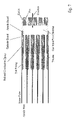
- FIG. 7 illustrates in cross sectional view of one end of a module of a closely packed array of straw tube detectors as this array is assembled with the cathode board—anode board of FIGS. 5 and 6 and as the anode wire of each straw tube detector is electrically connected to its corresponding terminal in the anode board.
- FIG. 8 illustrates an N ⁇ M matrix read out circuit for an N ⁇ M array of straw tube detectors assembled in a module.
- FIG. 9 plots the results of a Monte Carlo simulation for the efficiency with which one of the two neutron reaction products, either the 4 ⁇ or the 7 Li fragment, escape from a single thin 10 B 4 C layer into the gaseous interior of the straw.
- Use of layer thicknesses above about 1 ⁇ m have a significant impact upon sensitivity.
- FIG. 10 plots the thermal neutron detection efficiency of 5 cm and 10 cm deep closely packed arrays of straw detectors of diameter of 4 mm, as a function of the thickness of the B 4 C layer lining each straw.
- the efficiency of a single planar layer of B 4 C is simulated as well, assuming gamma ray escape is detected at one face only.
- FIG. 11 plots the results of a Monte Carlo simulation for the flux (top) and dose (bottom) sensitivities of a proposed 5 cm deep array of closely packed straw detectors, in which each straw is made out of the material indicated and whose wall thickness is 35 ⁇ m. It is assumed that the thin B4C layer (approximately 1 ⁇ m does not contribute significantly to gamma sensitivity).
- This invention involves many materials and many associations of such materials and elements made there from all to the purpose of the creation of a neutron detector of practical utility, of a large area detection capability, and in its preferred embodiment a capability of detecting neutron interaction within a reasonably precise spatial location of such large area neutron detector.
- thermal neutrons The detection of thermal neutrons is based on the generation of secondary radiations, following the capture of neutrons in a converter material.
- a converter material reaction commonly used is that of neutron (n) capture in boron-10 ( 10 B), described by, 10 B+ n ⁇ 7 Li+ 4 ⁇ (2.792 MeV, ground state) and 7 Li*+ 4 ⁇ (2.310 MeV, excited state).
- the energy released by the reaction is 2.310 million electron volts (MeV) in 94% of all reactions (2.792 MeV in the remaining 6%), and equals the energy imparted to the two reaction products (the energy of the captured neutron is negligible by comparison).
- the reaction products namely an alpha particle ( ⁇ ) and a lithium nucleus ( 7 Li) are emitted isotropically from the point of neutron capture by 10 B in exactly opposite directions and, in the case of the dominant excited state, with kinetic energies of 1.47 MeV and 0.84 MeV, respectively (dictated by the conservation of energy and momentum).
- Boron-lined proportional detectors based on the general principle above described have been employed for many years, but such detectors achieve at most a few percent efficiency, due to the fact that the single or at most two 10 B foil thicknesses therein needed for a substantial capture of such neutrons exceeds the escape range of the neutron capture reaction products; so in many instances, capture reaction products can not escape. (the optimal thickness in boron coated detectors currently is 1 mg/cm 2 ) Thus, only conversions of neutrons in a very thin layer near the surface of the 10 B foil adjacent the counting gas are detected efficiently. Since this very thin layer of the 10 B foil captures only a very small percentage of the incident neutrons, efficiency of a neutron detector of such simple design is low.
- Preparing the 10 B converter in the form of a very thin layer on the inside wall of a thin walled cylinder structure allows one of the two charged reaction particles (the one directed inward, whether alpha or 7 Li) to escape and be counted, through ionization of the counter gas.
- the opposing reaction particle cannot penetrate the wall of even a very thin cylinder and thus does not excite an adjacent detector cylinder. Therefore, when a thin cylinder structure with a very thin interior coating of 10 B is utilized, highly accurate location of the interaction reaction can be obtained.
- One embodiment of the new detector design of this invention employs a closely-packed array of 10 B 4 C-vey thin layer lined straw tubes. This design hence removes the barrier to efficient neutron capture reaction product escape while still providing for efficient neutron capture by providing a plurality of very thin 10 B converters, each individual converter layer providing efficient reaction product escape. Using multiple stacks of such straw tube detectors, a reasonable stack depth allows a high neutron detection efficiency to be achieved in the 1–10 ⁇ wavelength range of thermal neutrons. Furthermore, the elemental component of such detector, the straw tube element, may be made to have a very low sensitivity to gamma radiation, which is an essential attribute in many applications.
- a narrow film having one surface coated with a layer of 10 B, preferably in the form of B 4 C, preferably of a thickness of 0.5 to 3 ⁇ m.
- B 4 C coated narrow film strips or ribbons there is produced small diameter straw tubes of up to 2 meters in length having the thin layer of B 4 C preferably of a thickness of 0.5 to 3 ⁇ m on their interior surface.
- Such straws tubes are then installed with an end fitting means, affixed in each end of said straw tube, which is capable of receiving and positioning a wire centrally within said straw tube out of electrical contact with said coating of B 4 C and capable of allowing a flow of gas through said tube.
- the straw tube detector element 10 comprises a straw tube body 12 the interior surface of which carries a B 4 C coating 14 and an anode wire 16 which is centrally located in tube 12 out of electrical contact with the B 4 C coating 14 .
- the B 4 C coating has an enriched content of 10 B compared to the natural abundance of 10 B in elemental B.
- the thickness of the B 4 C layer is not greater than the thickness of B 4 C through which the neutron capture reaction products can penetrate, or escape, i.e., no greater than about 3.5 ⁇ m.
- B 4 C is a preferred material from which to form the thin 10 B layer
- alternative 10 B containing substances can be used, such as elemental B, B 10 H 14 , BN, B 2 O 3 , B 6 Si, B 3 Si, B 2 S 5 , B 2 S 3 and the like.
- Aluminum and plastic were evaluated as backing film materials for a B 4 C coating and as the base material for the straw tube body.
- Mylar®(C 5 H 4 O 2 ) plastic film was used. Since the density of aluminum (2.7 g/cm 3 ) is nearly double that of Mylar® (1.4 g/cm 3 ), the plastic is advantageous with respect to minimization of gamma ray sensitivity.
- Another criterion in selection of the straw material is maintenance of structural integrity. Any other plastic film forming material of a density less that aluminum may be employed. Such plastic materials for straw formation are well known to those skilled in the art.
- B 4 C Boron, in the form of boron carbide (B 4 C), was vapor deposited on aluminum and Mylar® foils using a plasma deposition process.
- the B 4 C coating was found to be extremely adherent and mechanically stable when applied to substances like aluminum and plastics. Deposition was accomplished by wrapping narrow 9.5 mm wide and 25 ⁇ m thick strips or ribbons of the respective materials around a cylindrical drum (16′′ diameter ⁇ 16′′ long), which thereafter was rotated adjacent to a sputtering head. A tape running down the side of the drum kept the strips in place (but also produced a 1 cm dead space every 50′′). Using this process, a highly uniform boron carbide coating was achieved on continuous strips of material with a length up to 50 meters. Such continuous material is required in straw construction, which utilizes high speed automated equipment.
- Straws are manufactured using a high speed winding technique in which narrow ribbons of plastic or metal-coated plastic film are helically wound around a cylindrical mandrel of precise dimension. Quickset adhesive may be applied to the film on the fly to instantly bond the multiple layers of plastic film together. In this manner, large quantities can be produced at high rates and thus low cost.
- the straw tube preferably has an areal density (weight of the straw tube divided by the surface area of the straw tube) of less than 90 mg/cm 2.
- an anode wire is precisely centered within the straw tube. Although laborious, this wire installation-centering could be done on a straw by straw basis and then the anode wire installed tubes could be assembled into an array of straws. However, the preferred assembly procedure for the large area thermal neutron detector is described below.
- a large area detector based on this straw technology can be achieved practically by dividing the detector into a modest number of independent modules, each consisting of an N ⁇ M array of straws. For example, using 50 straw modules, a 5 cm thick, 1 m 2 detector, consisting of about 3600 straws, would consist of 72 modules in a close packed configuration. Thus, the feasibility of production of densely packed large-area arrays of such straw tube detectors depends upon practical and relatively low-cost methods of module fabrication and readout. Although each straw tube detector serves as an individual detection element, the module serves as a basic structural and readout unit. Therefore, techniques for volume fabrication and assembly in modules were considered from the outset and developed hand-in-hand with the straw tube detector design.
- FIG. 7 shows a cross-sectional schematic of the module design.
- a “twister” component shown in greater detail in FIG. 3 , was developed to permit precise wire centering.
- the twister component was machined from a high performance insulating polymer which provides excellent mechanical properties and can be machined and bonded easily, for example Ultem® 1000 (General Electric Company).
- Ultem® 1000 General Electric Company
- the twister 20 has a helical structure and its length may be about 0.110′′–0.115′′. In any given thin cross-section of the twister over half of the cross-sectional area 21 of the twister is open space 24 .
- FIG. 4 view B the twister 20 is housed inside a simple end fitting sleeve 30 (view A of FIG. 4 ), which was manufactured on a bench lathe from a high performance insulating polymer which provides excellent mechanical properties and can be machined and bonded easily, for example from Ultem® 1000.
- the end fitting sleeve is open-ended 32 and 34 and has a bottle-shape and a central channel 36 that tapers in slightly to form a shoulder 38 so that the twister 20 can be seated firmly against shoulder 38 .
- the twister component may be permanently affixed inside the end fitting sleeve, and identical end fittings 50 , comprising a sleeve and twister, are epoxies into each end of the straw. While the base 40 of the fitting sleeve 30 sits inside the straw, a ‘neck’ 42 of a reduced diameter protrudes out and serves as a male connector to a fiberglass board assembly that is mounted at each end of the array.
- FIGS. 5–7 a dual-board assembly was developed that permits electrical connection, gas flow, and wire tensioning.
- This assembly consists of two (fiberglass) circuit boards preferably of fiberglass, a cathode board 52 as shown in FIG. 5 and an anode board 54 as shown in FIG. 6 .
- the neck 42 of straw end fittings 50 plug into apertures 57 positioned through the outer face 56 of the cathode board, which is coated with a uniform conductive layer, facilitating a single common high voltage connection.
- FIG. 5 illustrates the cathode board 52 from the perspective of its outer face 56 whereas the cathode board 52 in cross sectional view may be seen in FIG. 7 .
- Cathode board 52 is prepared with apertures 57 that are dimensioned to receive the neck 42 of the sleeve of a tube end fitting. Apertures 57 are positioned across the outer face 56 of cathode board 52 in a pattern that corresponds to a straw tube array that will plug into the cathode board.
- the cathode board 52 incorporates a milled recess 66 and a protruding lip 68 .
- each pad on the anode board 54 leads to a unique termination 58 adjacent to the corresponding aperture, or hole, in the cathode board.
- the anode board also included a hole 60 for a gas entry/exit port and high voltage connection.
- FIG. 7 the dual board design when assembled is also compatible with efficient threading, tensioning, and attachment of the anode wire. Anode wires are held with tension in electrical contact to the anode board using a tapered pin 62 and a brass eyelet 64 . This procedure is explained in further detail below. As seen in FIG.
- the anode board has an inset 70 milled around the edge of the anode board which corresponds to the protruding lip 68 of the cathode board.
- the two boards fit together snugly and form an interior cavity 72 .
- the straw end fittings form an open connection to the resulting chamber, which is fed by a gas port 60 of the anode board. In this manner, effective gas flow is achieved through a single entry and exit port.
- this dual board assembly is designed to have apertures 57 in the cathode board 52 and terminations 58 in the anode board 54 that match precisely the cross sectional area of a straw array, so that modules of straws can then be closely packed to form a large area detector, if desired. Electrical contact between the anode wire and the anode board is achieved using a brass eyelet 64 .
- straws are cleanly cut into the desired lengths, for example 10 cm.
- Assembly of straws into closely packed honeycomb-like arrays is quite feasible by constructing individual rows, which are then stacked vertically. After inserting the twister-sleeve end fitting inside the straws, straws are arranged adjacent to each other atop a granite slab to ensure linearity.
- An alignment device may be used to gently hold the tubes in place while they are bonded together using spot application of fast setting cement applied with a hypodermic syringe. Each layer is then positioned so that straws of one layer fit into grooves created by the top of an underlying row of straws. This assembly technique results in very sturdy straw tube arrays.
- the preconstructed straw tube array is connected to the cathode board.
- Conductive epoxy is liberally applied to the inside surfaces of the apertures 57 in the cathode board 52 , and the straw array is plugged into the cathode board.
- the displacement of excess epoxy provides a secure electrical connection between the 10 B 4 C interior cathode shells and the cathode board which is coated with a uniform conductive layer. This process is performed for both ends of the array.
- the connection provides a secure seal, preventing gas leakage, and helps to maintain structural integrity.
- Using a micro drop of conductive epoxy an eyelet is then affixed in each termination hole 58 of the anode board 54 , thereby establishing electrical connection and fixation.
- Non-conductive epoxy is then applied around the edge of each eyelet forming a tight seal to prevent gas leakage.
- the anode board is then mated to the cathode board through the lip 68 of the cathode board 52 and the inset 70 milled around the edges of the anode board 54 , and the lip-inset connection is sealed using epoxy to prevent gas leakage.
- Two redundant high voltage connectors and a gas flow port through aperture 60 are also connected to the anode board.
- the final product is shown in FIG. 7 .
- a module consisting of a straw tube array with a dual-board assembly structure mounted on each end, is mounted in a jig.
- a gas-driven threading system is implemented by connecting compressed gas, such as argon, (about 15 psi) through a plastic hose to a length of small diameter copper tubing in which a small hole has been drilled that approximates the diameter of the anode wire to be used.
- the copper tubing is inserted through a termination hole 58 in the anode board, through the chamber 72 , and down to the end fitting of the straw tube corresponding to that termination hole.
- a columnar gas flow through the copper tubing and the straw tube is created.
- a spool of anode wire is positioned at one end of the setup, and anode wire is inserted through the small hole drilled in the copper tubing.
- the rapid gas jet produces sufficient tension in the wire so that it may be easily fed through the straw by simply rotating the source wire reel until the wire appears at the output end of the straw.
- the copper tubing is removed, and a small brass pin 62 as illustrated in FIG.
- FIG. 7 illustrates one end of a modular assembly of closely packed straw tube detectors with anode wires installed and electrical connections between the cathode board and the B 4 C cathode interior shell coating and between the anode wires of each tube with its respective anode board termination 58 is shown as all elements thereof are in their operative assembly. Not illustrated in FIG. 7 is the operative connection of gas part 60 in one anode board end since means for such connection to a counter gas, as like Ar 98%-ethane 2%, would be readily apparent to one skilled in the art.
- neutron spectra were taken for four different gas mixtures: Ar/C 2 H 6 (50/50), Ar/C 2 H 6 (72/28), Ar/C 2 H 6 (92/8), and Ar/C 2 H 6 (98/2).
- the operating voltage for read out for each mixture was chosen so that spectra could be taken at an equivalent charge gain of about 104, as determined by the amplitude of pulses from 5.9 keV 55 Fe X-rays.
- ethane quench gas For a constant gain, a reduced amount of ethane quench gas improves the distinction between the rapidly falling, low deposited energy gamma events, and the neutron events that form a broad peak in the upper higher energy channels. Using a small percentage admixture of ethane quench is also beneficial from the perspective of lifetime extension since there will be less hydrocarbon available to polymerize and deposit onto the anode wire.
- a 98/2 mixture of Ar/C 2 H 6 minimizes the saturation of neutron events seen at high gains and should increase the lifetime of the straw detector.
- Delay line readout offers a viable approach because signals from several inputs can be differentiated based on time of arrival. Taking advantage of the high anode resistivity and using additional termination resistors, straws can be connected along rows on one end and along columns on the other end, as illustrated in FIG. 8 .
- the module is read out as an N ⁇ M matrix using two multitap delay lines, one for rows and one for columns. Difference in time of signal arrival enable determination of which row and column fired. Because it requires a relatively low number of electronics components, the technique can be implemented quite cost effectively.
- One end of the straw array module had only a passive U-connection board, where each pair of adjacent straw anodes were connected together, so that all readout electronics may be placed on the other end.
- This scheme also reduced the number of taps needed on the delay line.
- the straw array illustrated by FIG. 8 is actually a 5 ⁇ 4 row-column matrix, it was read out as a 5 ⁇ 2 matrix of 20 cm long “effective”, U-connected straws, which had both readout ends on the same end of the module.
- the “effective straws” of the above example were connected together through resistors along rows on one end and along columns on the other end. Each row was connected to a tap in a 5-tap delay line, and each column was connected to a tap in a 2-tap delay line. Since each tap delays the signal by a fixed time, the difference in time of arrival at each end of the delay line indicated which row or column contained the firing straw. Events were histogrammed based on the differences in arrival times, and a count profile was generated for each delay line. For each delay line, the outputs from both ends of the delay line were also summed together to give A and B signals. Thus, spatial resolution was measured using an A/(A+B) charge division technique with A and B measurement performed with a charge integrating ADC.
- a generic straw detector module may be constructed distinct from the electronics used to read it out. Varying electronics modules can then be used to process these signals according to the needs of the specific application.
- a fully 3D readout system can be employed simply by using a more advanced plug-in electronics module.
- This 3D module will interface with the detector in the same way as the 2D module did, but will incorporate a delay-line readout system in both the row and column directions. This will allow the detector to read out an accurate 3D position.
- Both 2D and 3D plug-in electronics modules may be built that achieve high position resolution and can interface with a large array of neutron straws.
- the thermal neutron sensitivity of a 10 ⁇ 5 array of straws was measured.
- the array was populated by 34 active straws of the 4 mm diameter and 77 mm active length, and with a B 4 C thickness of 2 ⁇ m. All anodes were tied together, such that events were registered from any one of the 34 straws.
- a neutron source was placed 10 inch away, and the flux was measured with a BF 3 tube. For a flux of 5.04 nv, there were 17.3 neutron counts per second in the array, resulting in a sensitivity of 3.4 cps/nv. This sensitivity predicts a single tube sensitivity of 0.10 cps/nv, which agrees very well with the value of 0.09 cps/nv measured for a single straw.
- a 1 meter straw was constructed.
- the length of such a straw creates an issue of wire electrostatic instability.
- an additional twister with an Ultem housing sleeve, was positioned precisely at the center of the 1 m length.
- the twister was contained in a cylindrical shell, open on both ends, permitting the gas driven wire placement.
- the twister shell was tacked in place by piercing the straw body with a small gauge hypodermic needle and injecting a small drop of epoxy.
Landscapes
- Physics & Mathematics (AREA)
- High Energy & Nuclear Physics (AREA)
- Health & Medical Sciences (AREA)
- Life Sciences & Earth Sciences (AREA)
- General Physics & Mathematics (AREA)
- Molecular Biology (AREA)
- Spectroscopy & Molecular Physics (AREA)
- Chemical & Material Sciences (AREA)
- Engineering & Computer Science (AREA)
- Chemical Kinetics & Catalysis (AREA)
- Materials Engineering (AREA)
- Measurement Of Radiation (AREA)
Abstract
Description
ε=f e(1−e −Nat)
where fe is the escape efficiency, σ is the neutron cross section for the 10B (n, a) reaction and N is the effective nuclear density of 10B in a detector array of depth t. The neutron cross section is a function of the wavelength λ of the neutron, given by σ=2133 λ (for λ in Å and σin barns). The nuclear density N is computed as N=NB(πd)/(0.866 D) where D is the straw tube diameter, d the 10B4C film thickness in each straw, and NB the nuclear density of 10B in 10B-enriched B4C (1.10×10²³ atoms/cm3). The predicted efficiency for room temperature thermal neutrons (0.0253 eV) is plotted in
10B+n→ 7Li+4α(2.792 MeV, ground state) and 7Li*+4α(2.310 MeV, excited state).
Claims (21)
Priority Applications (1)
| Application Number | Priority Date | Filing Date | Title |
|---|---|---|---|
| US10/712,692 US7002159B2 (en) | 2002-11-13 | 2003-11-13 | Boron coated straw neutron detector |
Applications Claiming Priority (2)
| Application Number | Priority Date | Filing Date | Title |
|---|---|---|---|
| US42598402P | 2002-11-13 | 2002-11-13 | |
| US10/712,692 US7002159B2 (en) | 2002-11-13 | 2003-11-13 | Boron coated straw neutron detector |
Publications (2)
| Publication Number | Publication Date |
|---|---|
| US20050258373A1 US20050258373A1 (en) | 2005-11-24 |
| US7002159B2 true US7002159B2 (en) | 2006-02-21 |
Family
ID=32313092
Family Applications (1)
| Application Number | Title | Priority Date | Filing Date |
|---|---|---|---|
| US10/712,692 Expired - Lifetime US7002159B2 (en) | 2002-11-13 | 2003-11-13 | Boron coated straw neutron detector |
Country Status (4)
| Country | Link |
|---|---|
| US (1) | US7002159B2 (en) |
| EP (1) | EP1578375B1 (en) |
| AU (1) | AU2003299556A1 (en) |
| WO (1) | WO2004043372A2 (en) |
Cited By (28)
| Publication number | Priority date | Publication date | Assignee | Title |
|---|---|---|---|---|
| US20060043308A1 (en) * | 2004-07-29 | 2006-03-02 | Mcgregor Douglas S | Micro neutron detectors |
| US20100163744A1 (en) * | 2008-06-16 | 2010-07-01 | Jeffrey Lacy | Long Range Neutron-Gamma Point Source Detection and Imaging Using Rotating Detector |
| US20100258735A1 (en) * | 2009-04-13 | 2010-10-14 | General Electronic Company | B10 neutron detector in pie shaped sectors |
| US20100258733A1 (en) * | 2009-04-13 | 2010-10-14 | General Electric Company | Composite dielectric fins in enhanced area boron coated neutron detectors |
| US20100258736A1 (en) * | 2009-04-13 | 2010-10-14 | General Electric Company | neutron sensitivity by increasing boron surface area |
| US20100258734A1 (en) * | 2009-04-13 | 2010-10-14 | General Electric Company | Neutron sensitivity using detector arrays |
| US20100301226A1 (en) * | 2009-06-02 | 2010-12-02 | Lacy Jeffrey L | Optimized Detection of Fission Neutrons Using Boron Coated Straw Detectors Distributed in Moderator Material |
| US20100314549A1 (en) * | 2009-06-15 | 2010-12-16 | Los Alamos National Security, Llc | Neutron detectors comprising boron powder |
| US20110116589A1 (en) * | 2009-11-16 | 2011-05-19 | General Electric Company | Water based dispersions of boron or boron compounds for use in coating boron lined neutron detectors |
| US7964852B2 (en) | 2009-09-18 | 2011-06-21 | General Electric Company | Neutron sensitivity using detector arrays |
| US20110272570A1 (en) * | 2010-05-04 | 2011-11-10 | Smith International, Inc. | Method and Apparatus for Neutron Logging Using a Position Sensitive Neutron Detector |
| US20120161023A1 (en) * | 2009-06-15 | 2012-06-28 | Los Alamos National Security, Llc | Neutron detectors comprising ultra-thin layers of boron powder |
| US8319175B2 (en) | 2010-08-31 | 2012-11-27 | Schlumberger Technology Corporation | Nano-tips based gas ionization chamber for neutron detection |
| US8399849B1 (en) | 2009-08-08 | 2013-03-19 | Redpine Signals, Inc | Fast neutron detector |
| WO2013119301A2 (en) | 2011-11-22 | 2013-08-15 | Lacy Jeffrey L | Boron-coated straw detectors with shaped straws |
| US20140110593A1 (en) * | 2012-10-22 | 2014-04-24 | Proportional Technologies, Inc. | Method and Apparatus for Fabricating Boron Coated Straws for Neutron Detectors |
| WO2014065990A1 (en) * | 2012-10-25 | 2014-05-01 | Schlumberger Canada Limited | Apparatus and method for detecting radiation |
| US8729487B2 (en) | 2011-09-15 | 2014-05-20 | Material Innovations, Inc. | Neutron detector and method of making |
| WO2014120295A3 (en) * | 2012-10-22 | 2014-10-02 | Proportional Technologies, Inc. | Coating thin foil with boron |
| US8973257B2 (en) | 2011-09-15 | 2015-03-10 | Material Innovations, Inc. | Method of making a neutron detector |
| US9213111B2 (en) | 2010-05-12 | 2015-12-15 | Proportional Technologies, Inc. | Neutron detectors for active interrogation |
| US9218946B2 (en) | 2010-05-13 | 2015-12-22 | Proportional Technologies, Inc. | Sealed boron coated straw detectors |
| JP2017120251A (en) * | 2015-12-29 | 2017-07-06 | 清華大学Tsinghua University | Low-speed neutron converter and low-speed neutron detector |
| US9817138B2 (en) | 2009-08-27 | 2017-11-14 | Douglas S. McGregor | Gas-filled neutron detectors and imaging system and array of such detectors |
| WO2018093418A1 (en) * | 2016-05-23 | 2018-05-24 | Proportional Technologies, Inc. | Method of manufacturing boron coated straws for neutron detection through spiral winding and welding |
| US10139501B2 (en) * | 2016-10-18 | 2018-11-27 | Proportional Technologies, Inc. | Boron coated straws for neutron detection with pie-shaped cross-section |
| US10613238B2 (en) * | 2016-10-18 | 2020-04-07 | Proportional Technologies, Inc. | Boron coated straws for neutron detection with pie-shaped cross-section |
| US11009616B2 (en) | 2014-05-14 | 2021-05-18 | Symetrica Limited | Neutron detection |
Families Citing this family (24)
| Publication number | Priority date | Publication date | Assignee | Title |
|---|---|---|---|---|
| US7456405B1 (en) * | 2004-03-08 | 2008-11-25 | Thermo Fisher Scientific Inc. | Portable radiation monitor methods and apparatus |
| KR101124549B1 (en) * | 2007-04-24 | 2012-03-20 | 가부시끼가이샤 도시바 | Radiography measuring device and radiography measuring method |
| FR2937149B1 (en) * | 2008-10-13 | 2010-12-03 | Commissariat Energie Atomique | DEVICE FOR ONLINE MEASUREMENT OF A FAST AND EPITHERMIC NEUTRON STREAM |
| FR2957188B1 (en) * | 2010-03-02 | 2012-08-17 | Laue Max Inst | IONIZING RADIATION DETECTOR |
| FR2960303B1 (en) | 2010-05-18 | 2013-04-05 | Onectra | NEUTRON DETECTION APPARATUS AND METHOD OF DEPOSITING A SOLID BORON LAYER FOR SUCH AN APPARATUS |
| CN102749641B (en) * | 2011-04-18 | 2015-11-25 | 同方威视技术股份有限公司 | Be coated with boron neutron detector and manufacture method thereof |
| EP2726640B1 (en) * | 2011-06-30 | 2021-12-08 | European Spallation Source ERIC | A method for producing a neutron detector component comprising a boron carbide layer for use in a neutron detecting device |
| CA2776093A1 (en) * | 2011-09-22 | 2013-03-22 | Sture Petersson | Neutron detector |
| US8569711B2 (en) | 2011-12-21 | 2013-10-29 | General Electric Company | HE-3 tube array alignment mount |
| US10088580B2 (en) | 2012-05-31 | 2018-10-02 | Minnesota Imaging And Engineering Llc | Detector systems for radiation imaging |
| US10067239B2 (en) | 2012-05-31 | 2018-09-04 | Minnesota Imaging And Engineering Llc | Detector systems for radiation imaging |
| US10371834B2 (en) * | 2012-05-31 | 2019-08-06 | Minnesota Imaging And Engineering Llc | Detector systems for integrated radiation imaging |
| US9651689B2 (en) | 2013-06-24 | 2017-05-16 | Arktis Radiation Detectors Ltd | Detector arrangement for the detection of ionizing radiation and method for operating such a detector arrangement |
| CN103305791B (en) * | 2013-06-25 | 2015-10-07 | 四川大学 | Preparation method of 6LiF/10B4C composite neutron conversion thin film for 4H-SiC based neutron detector |
| RU2602492C2 (en) * | 2014-08-20 | 2016-11-20 | Объединенный Институт Ядерных Исследований | Device for measuring the location of wires in gas wire chambers |
| HK1246399A1 (en) | 2014-12-22 | 2018-09-07 | Arktis Radiation Detectors Ltd. | Neutron conversion foil, neutron detecting device with such a foil, and method for operating such a neutron-detecting device |
| CN104778982A (en) * | 2015-04-09 | 2015-07-15 | 中国核动力研究设计院 | Luenberger type H2 filtering based rhodium self-powered detector signal delay elimination method |
| US10509135B2 (en) | 2016-09-09 | 2019-12-17 | Minnesota Imaging And Engineering Llc | Structured detectors and detector systems for radiation imaging |
| US10365383B2 (en) | 2016-09-09 | 2019-07-30 | Minnesota Imaging And Engineering Llc | Structured detectors and detector systems for radiation imaging |
| US10502849B1 (en) * | 2018-07-20 | 2019-12-10 | Baker Hughes Oilfield Operations Llc | Pseudogas neutron detector |
| US11029429B2 (en) | 2018-07-20 | 2021-06-08 | Baker Hughes Oilfield Operations Llc | Pseudogas neutron detector |
| WO2020226900A2 (en) | 2019-04-23 | 2020-11-12 | Cerium Laboratories Llc | Radiation detection systems and methods |
| US12235398B2 (en) | 2021-05-03 | 2025-02-25 | Cerium Laboratories, Llc | Radiation detection systems and methods |
| CN113341453B (en) * | 2021-07-06 | 2022-12-13 | 散裂中子源科学中心 | White light neutron imaging method and system for nuclide identification |
Citations (3)
| Publication number | Priority date | Publication date | Assignee | Title |
|---|---|---|---|---|
| US3483377A (en) * | 1967-11-03 | 1969-12-09 | Atomic Energy Commission | Position-sensitive radiation detector |
| US4359372A (en) * | 1979-10-11 | 1982-11-16 | Matsushita Electric Industrial Company, Limited | Method for making a carbide thin film thermistor |
| US4695476A (en) * | 1985-06-06 | 1987-09-22 | Westinghouse Electric Corp. | Process for coating the internal surface of zirconium tubes with neutron absorbers |
Family Cites Families (4)
| Publication number | Priority date | Publication date | Assignee | Title |
|---|---|---|---|---|
| US6263291B1 (en) * | 1997-12-11 | 2001-07-17 | Metso Paper Automation Inc. | Method and apparatus for measuring color and/or composition |
| EP1169623B1 (en) * | 2000-02-15 | 2013-12-18 | Agilent Technologies Australia (M) Pty Ltd | Optical shutter for spectroscopy instrument |
| US6798518B2 (en) * | 2002-06-04 | 2004-09-28 | Baker Hughes Incorporated | Method and apparatus for a derivative spectrometer |
| US8088628B2 (en) * | 2002-09-30 | 2012-01-03 | Intel Corporation | Stimulated and coherent anti-stokes raman spectroscopic methods for the detection of molecules |
-
2003
- 2003-11-05 EP EP03799842.4A patent/EP1578375B1/en not_active Expired - Lifetime
- 2003-11-05 AU AU2003299556A patent/AU2003299556A1/en not_active Abandoned
- 2003-11-05 WO PCT/US2003/035469 patent/WO2004043372A2/en not_active Ceased
- 2003-11-13 US US10/712,692 patent/US7002159B2/en not_active Expired - Lifetime
Patent Citations (3)
| Publication number | Priority date | Publication date | Assignee | Title |
|---|---|---|---|---|
| US3483377A (en) * | 1967-11-03 | 1969-12-09 | Atomic Energy Commission | Position-sensitive radiation detector |
| US4359372A (en) * | 1979-10-11 | 1982-11-16 | Matsushita Electric Industrial Company, Limited | Method for making a carbide thin film thermistor |
| US4695476A (en) * | 1985-06-06 | 1987-09-22 | Westinghouse Electric Corp. | Process for coating the internal surface of zirconium tubes with neutron absorbers |
Cited By (53)
| Publication number | Priority date | Publication date | Assignee | Title |
|---|---|---|---|---|
| US20060043308A1 (en) * | 2004-07-29 | 2006-03-02 | Mcgregor Douglas S | Micro neutron detectors |
| US20060056573A1 (en) * | 2004-07-29 | 2006-03-16 | Mcgregor Douglas S | Micro neutron detectors |
| US20070018110A1 (en) * | 2004-07-29 | 2007-01-25 | Mcgregor Douglas S | Micro neutron detectors |
| US20100163744A1 (en) * | 2008-06-16 | 2010-07-01 | Jeffrey Lacy | Long Range Neutron-Gamma Point Source Detection and Imaging Using Rotating Detector |
| US8330116B2 (en) | 2008-06-16 | 2012-12-11 | Proportional Technologies, Inc. | Long range neutron-gamma point source detection and imaging using rotating detector |
| US9606248B2 (en) | 2009-04-13 | 2017-03-28 | General Electric Company | Neutron sensitivity using detector arrays |
| US7952078B2 (en) | 2009-04-13 | 2011-05-31 | General Electric Company | Neutron sensitivity by increasing boron surface area |
| US20100258734A1 (en) * | 2009-04-13 | 2010-10-14 | General Electric Company | Neutron sensitivity using detector arrays |
| US20100258735A1 (en) * | 2009-04-13 | 2010-10-14 | General Electronic Company | B10 neutron detector in pie shaped sectors |
| US8084747B2 (en) | 2009-04-13 | 2011-12-27 | General Electric | Composite dielectric fins in enhanced area boron coated neutron detectors |
| US20100258736A1 (en) * | 2009-04-13 | 2010-10-14 | General Electric Company | neutron sensitivity by increasing boron surface area |
| US7910893B2 (en) | 2009-04-13 | 2011-03-22 | General Electric Company | B10 neutron detector in pie shaped sectors |
| US20100258733A1 (en) * | 2009-04-13 | 2010-10-14 | General Electric Company | Composite dielectric fins in enhanced area boron coated neutron detectors |
| WO2011019437A1 (en) | 2009-06-02 | 2011-02-17 | Lacy Jeffrey L | Optimized detection of fission neutrons using boron coated straw detectors distributed in moderator material |
| US8569710B2 (en) * | 2009-06-02 | 2013-10-29 | Proportional Technologies, Inc. | Optimized detection of fission neutrons using boron coated straw detectors distributed in moderator material |
| US20100301226A1 (en) * | 2009-06-02 | 2010-12-02 | Lacy Jeffrey L | Optimized Detection of Fission Neutrons Using Boron Coated Straw Detectors Distributed in Moderator Material |
| US20100314549A1 (en) * | 2009-06-15 | 2010-12-16 | Los Alamos National Security, Llc | Neutron detectors comprising boron powder |
| US8492730B2 (en) * | 2009-06-15 | 2013-07-23 | Los Alamos National Security, Llc | Neutron detectors comprising ultra-thin layers of boron powder |
| US20120161023A1 (en) * | 2009-06-15 | 2012-06-28 | Los Alamos National Security, Llc | Neutron detectors comprising ultra-thin layers of boron powder |
| US8445859B2 (en) * | 2009-06-15 | 2013-05-21 | Los Alamos National Security, Llc | Neutron detectors comprising boron powder |
| US8399849B1 (en) | 2009-08-08 | 2013-03-19 | Redpine Signals, Inc | Fast neutron detector |
| US9817138B2 (en) | 2009-08-27 | 2017-11-14 | Douglas S. McGregor | Gas-filled neutron detectors and imaging system and array of such detectors |
| US7964852B2 (en) | 2009-09-18 | 2011-06-21 | General Electric Company | Neutron sensitivity using detector arrays |
| US8565364B2 (en) * | 2009-11-16 | 2013-10-22 | General Electric Company | Water based dispersions of boron or boron compounds for use in coating boron lined neutron detectors |
| US20110116589A1 (en) * | 2009-11-16 | 2011-05-19 | General Electric Company | Water based dispersions of boron or boron compounds for use in coating boron lined neutron detectors |
| GB2492718A (en) * | 2010-05-04 | 2013-01-09 | Smith International | Method and apparatus for neutron logging using a position sensitive neutron detector |
| WO2011140214A3 (en) * | 2010-05-04 | 2012-03-01 | Smith International, Inc. | Method and apparatus for neutron logging using a position sensitive neutron detector |
| US20110272570A1 (en) * | 2010-05-04 | 2011-11-10 | Smith International, Inc. | Method and Apparatus for Neutron Logging Using a Position Sensitive Neutron Detector |
| US8803078B2 (en) * | 2010-05-04 | 2014-08-12 | Schlumberger Technology Corporation | Method and apparatus for neutron logging using a position sensitive neutron detector |
| GB2492718B (en) * | 2010-05-04 | 2015-12-09 | Smith International | Method and apparatus for neutron logging using a position sensitive neutron detector |
| US9213111B2 (en) | 2010-05-12 | 2015-12-15 | Proportional Technologies, Inc. | Neutron detectors for active interrogation |
| US9218946B2 (en) | 2010-05-13 | 2015-12-22 | Proportional Technologies, Inc. | Sealed boron coated straw detectors |
| US8319175B2 (en) | 2010-08-31 | 2012-11-27 | Schlumberger Technology Corporation | Nano-tips based gas ionization chamber for neutron detection |
| US8729487B2 (en) | 2011-09-15 | 2014-05-20 | Material Innovations, Inc. | Neutron detector and method of making |
| US8973257B2 (en) | 2011-09-15 | 2015-03-10 | Material Innovations, Inc. | Method of making a neutron detector |
| WO2013119301A2 (en) | 2011-11-22 | 2013-08-15 | Lacy Jeffrey L | Boron-coated straw detectors with shaped straws |
| US8941075B2 (en) * | 2011-11-22 | 2015-01-27 | Proportional Technologies, Inc. | Boron-coated straw detectors with shaped straws |
| US20140061489A1 (en) * | 2011-11-22 | 2014-03-06 | Jeffrey L. Lacy | Boron-Coated Straw Detectors With Shaped Straws |
| WO2013119301A3 (en) * | 2011-11-22 | 2013-10-03 | Lacy Jeffrey L | Boron-coated straw detectors with shaped straws |
| WO2014109808A2 (en) | 2012-10-22 | 2014-07-17 | Proportional Technologies, Inc. | Method and apparatus for fabricating boron coated straws for neutron detectors |
| US20140110593A1 (en) * | 2012-10-22 | 2014-04-24 | Proportional Technologies, Inc. | Method and Apparatus for Fabricating Boron Coated Straws for Neutron Detectors |
| WO2014120295A3 (en) * | 2012-10-22 | 2014-10-02 | Proportional Technologies, Inc. | Coating thin foil with boron |
| US9217793B2 (en) | 2012-10-25 | 2015-12-22 | Schlumberger Technology Corporation | Apparatus and method for detecting radiation |
| WO2014065990A1 (en) * | 2012-10-25 | 2014-05-01 | Schlumberger Canada Limited | Apparatus and method for detecting radiation |
| US11009616B2 (en) | 2014-05-14 | 2021-05-18 | Symetrica Limited | Neutron detection |
| JP2017120251A (en) * | 2015-12-29 | 2017-07-06 | 清華大学Tsinghua University | Low-speed neutron converter and low-speed neutron detector |
| AU2016234975A1 (en) * | 2015-12-29 | 2017-07-13 | Nuctech Company Limited | Slow neutron conversion body and slow neutron detector |
| AU2016234975B2 (en) * | 2015-12-29 | 2018-07-12 | Nuctech Company Limited | Slow neutron conversion body and slow neutron detector |
| US10126440B2 (en) | 2015-12-29 | 2018-11-13 | Tsinghua University | Slow neutron conversion body and slow neutron detector |
| WO2018093418A1 (en) * | 2016-05-23 | 2018-05-24 | Proportional Technologies, Inc. | Method of manufacturing boron coated straws for neutron detection through spiral winding and welding |
| US10974300B2 (en) | 2016-05-23 | 2021-04-13 | Proportional Technologies, Inc. | Method of manufacturing boron coated straws for neutron detection through spiral winding and welding |
| US10139501B2 (en) * | 2016-10-18 | 2018-11-27 | Proportional Technologies, Inc. | Boron coated straws for neutron detection with pie-shaped cross-section |
| US10613238B2 (en) * | 2016-10-18 | 2020-04-07 | Proportional Technologies, Inc. | Boron coated straws for neutron detection with pie-shaped cross-section |
Also Published As
| Publication number | Publication date |
|---|---|
| AU2003299556A8 (en) | 2004-06-03 |
| WO2004043372A2 (en) | 2004-05-27 |
| EP1578375A2 (en) | 2005-09-28 |
| WO2004043372A3 (en) | 2005-08-25 |
| EP1578375B1 (en) | 2018-01-03 |
| AU2003299556A1 (en) | 2004-06-03 |
| EP1578375A4 (en) | 2007-05-09 |
| US20050258373A1 (en) | 2005-11-24 |
Similar Documents
| Publication | Publication Date | Title |
|---|---|---|
| US7002159B2 (en) | Boron coated straw neutron detector | |
| Budtz-Jørgensen et al. | A twin ionization chamber for fission fragment detection | |
| (Zabierowsk et al. | The CELSIUS/WASA detector facility | |
| US9817138B2 (en) | Gas-filled neutron detectors and imaging system and array of such detectors | |
| US20060043308A1 (en) | Micro neutron detectors | |
| US8729487B2 (en) | Neutron detector and method of making | |
| Leprêtre et al. | Absolute photofission cross sections for 232Th and 235,238 U measured with monochromatic tagged photons (20 Mev< Eγ< 110 Mev) | |
| US8973257B2 (en) | Method of making a neutron detector | |
| Hong et al. | Plan for nuclear symmetry energy experiments using the LAMPS system at the RIB facility RAON in Korea | |
| Ishihara et al. | A proposed detector DCBA for double beta decay experiments | |
| WO2011143506A1 (en) | Sealed boron coated straw detectors | |
| Athanasiades et al. | Straw detector for high rate, high resolution neutron imaging | |
| Gidal et al. | Major detectors in elementary particle physics | |
| Moltz et al. | Development of low-energy proton detector telescopes | |
| Kim | Foil activation measurements of energy and flux of neutrons from DT mixed beams driven into a target | |
| Chiang et al. | Measurement of KL! 0 | |
| Castellano et al. | A transition radiation detector to measure the energy of cosmic ray muons in an underground laboratory | |
| Podolyák | PRESENT AND FUTURE OF HISPEC. | |
| Cugnon et al. | The pisa experiment: spallation products identified by bragg curve spectroscopy | |
| Mahgoub et al. | Building a multi-cathode gas-filled detector | |
| Glenn et al. | Measurement of K0 | |
| Schall et al. | Characterization of deuterium beam operation on RHEPP-1 for future neutron generation applications. | |
| Kalmus | The CERN proton-antiproton collider programme | |
| Wètherell | III. 1 NOTES ON ASPECTS OF HADRONIC EXPERIMENTS NITH A 10 TeV PROTON SYNCHROTRON | |
| Rossi | Perspectives in High Energy Physics Instrumentation |
Legal Events
| Date | Code | Title | Description |
|---|---|---|---|
| AS | Assignment |
Owner name: PROPORTIONAL TECHNOLOGIES, INC., TEXAS Free format text: ASSIGNMENT OF ASSIGNORS INTEREST;ASSIGNOR:LACY, JEFFREY L.;REEL/FRAME:014677/0769 Effective date: 20031230 |
|
| FPAY | Fee payment |
Year of fee payment: 4 |
|
| REMI | Maintenance fee reminder mailed | ||
| FEPP | Fee payment procedure |
Free format text: PAT HOLDER CLAIMS SMALL ENTITY STATUS, ENTITY STATUS SET TO SMALL (ORIGINAL EVENT CODE: LTOS); ENTITY STATUS OF PATENT OWNER: SMALL ENTITY Free format text: PETITION RELATED TO MAINTENANCE FEES GRANTED (ORIGINAL EVENT CODE: PMFG); ENTITY STATUS OF PATENT OWNER: SMALL ENTITY Free format text: PETITION RELATED TO MAINTENANCE FEES FILED (ORIGINAL EVENT CODE: PMFP); ENTITY STATUS OF PATENT OWNER: SMALL ENTITY |
|
| LAPS | Lapse for failure to pay maintenance fees | ||
| REIN | Reinstatement after maintenance fee payment confirmed | ||
| PRDP | Patent reinstated due to the acceptance of a late maintenance fee |
Effective date: 20140408 |
|
| FPAY | Fee payment |
Year of fee payment: 8 |
|
| STCF | Information on status: patent grant |
Free format text: PATENTED CASE |
|
| FP | Lapsed due to failure to pay maintenance fee |
Effective date: 20140221 |
|
| FEPP | Fee payment procedure |
Free format text: 11.5 YR SURCHARGE- LATE PMT W/IN 6 MO, SMALL ENTITY (ORIGINAL EVENT CODE: M2556) |
|
| MAFP | Maintenance fee payment |
Free format text: PAYMENT OF MAINTENANCE FEE, 12TH YR, SMALL ENTITY (ORIGINAL EVENT CODE: M2553) Year of fee payment: 12 |