US6998534B1 - Partition structure of a computer casing - Google Patents
Partition structure of a computer casing Download PDFInfo
- Publication number
- US6998534B1 US6998534B1 US10/968,113 US96811304A US6998534B1 US 6998534 B1 US6998534 B1 US 6998534B1 US 96811304 A US96811304 A US 96811304A US 6998534 B1 US6998534 B1 US 6998534B1
- Authority
- US
- United States
- Prior art keywords
- guide groove
- partition
- joining member
- casing
- horizontal guide
- Prior art date
- Legal status (The legal status is an assumption and is not a legal conclusion. Google has not performed a legal analysis and makes no representation as to the accuracy of the status listed.)
- Expired - Fee Related
Links
Images


Classifications
-
- G—PHYSICS
- G06—COMPUTING; CALCULATING OR COUNTING
- G06F—ELECTRIC DIGITAL DATA PROCESSING
- G06F1/00—Details not covered by groups G06F3/00 - G06F13/00 and G06F21/00
- G06F1/16—Constructional details or arrangements
- G06F1/18—Packaging or power distribution
- G06F1/183—Internal mounting support structures, e.g. for printed circuit boards, internal connecting means
-
- H—ELECTRICITY
- H05—ELECTRIC TECHNIQUES NOT OTHERWISE PROVIDED FOR
- H05K—PRINTED CIRCUITS; CASINGS OR CONSTRUCTIONAL DETAILS OF ELECTRIC APPARATUS; MANUFACTURE OF ASSEMBLAGES OF ELECTRICAL COMPONENTS
- H05K5/00—Casings, cabinets or drawers for electric apparatus
- H05K5/0004—Casings, cabinets or drawers for electric apparatus comprising several parts forming a closed casing
- H05K5/0008—Casings, cabinets or drawers for electric apparatus comprising several parts forming a closed casing assembled by screws
-
- H—ELECTRICITY
- H05—ELECTRIC TECHNIQUES NOT OTHERWISE PROVIDED FOR
- H05K—PRINTED CIRCUITS; CASINGS OR CONSTRUCTIONAL DETAILS OF ELECTRIC APPARATUS; MANUFACTURE OF ASSEMBLAGES OF ELECTRICAL COMPONENTS
- H05K5/00—Casings, cabinets or drawers for electric apparatus
- H05K5/0004—Casings, cabinets or drawers for electric apparatus comprising several parts forming a closed casing
- H05K5/0013—Casings, cabinets or drawers for electric apparatus comprising several parts forming a closed casing assembled by resilient members
Definitions
- the present invention is related to a partition structure of a computer casing, and particularly to a partition, which is provided with guide groove, so as to be engaged to the engaging parts of the joining member in a computer casing.
- a conventional computer casing 11 is attached with a partition 2 and a joining member 13 .
- the computer casing 11 has a fixing part 111 with a locating slot 111 a and fixing holes 111 b .
- the partition 12 has perforations 121 and the fasteners 121 a can pass through the perforations 121 to engage with the fixing holes 111 b .
- the partition 12 is capable of being fixedly attached to the computer casing 11 via the fasteners 121 a.
- the partition 12 has a first guide groove 122 and a second guide groove 123 .
- the first guide groove 122 further has a guide part 122 a and a locating part 122 b and the second guide groove 123 further has a guide part 123 a and a locating part 123 b .
- the joining member 13 which is provided with engaging parts 131 , 132 , engages with the locating parts 122 b , 123 b via the guide part 122 a of the first guide groove 122 and the guide part 123 a of the second guide groove 223 .
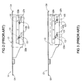
- the joining member 13 is tilted an angle first to allow the engaging part 132 of the joining member 13 enters via the guide part 123 a of the second guide groove 123 . Then, the engaging part 131 of the joining member 13 enters via the guide part 122 a of the first guide groove 122 as shown in FIG. 2 . Next, the engaging parts 131 , 132 slide along the first guide groove 122 and the second guide groove 123 a shown in FIG. 3 till the engaging parts 131 , 132 reaching the locating parts 122 b , 123 b as shown in FIG. 4 .
- the assembly of the partition 12 and the joining member 13 is attached to the computer casing 11 with the projections 124 at both end sides of the partition 12 insert into the locating slots 111 a next to the fixing holes 111 b . Further, the perforations 121 of the partition 12 align with the fixing holes 111 b of the computer casing 11 and the fasteners 121 a pass through the perforations 121 to engage with the fixing holes 111 b . Thus, the partition 12 is fixedly attached to the computer casing 11 .
- the fasteners 121 a have to be detached first. Then, the partition 12 with the joining member 13 is detached from the computer casing 11 . Finally, the partition 12 is disengaged from the joining member 13 following the reversed order shown in FIG. 4 , FIG. 3 and FIG. 2 sequentially. It is noted that either the partition 12 or the joining member 13 is incapable of being detached from the computer casing 11 directly and independently.
- the partition 12 of the computer casing 11 is primary for supporting the casing 11 against being deformed when the casing 11 is loaded with heavy objects such as data storage devices.
- the casing 11 has been reinforced with the partition 11 , the partition 12 and the joining member 13 have to be detached from casing 11 together before repair or parts replacing can be started.
- the partition 12 has to be taken out from the casing 11 before being detached from the joining member 13 in case of the data storage devices mounted to the joining member 13 needed to repair or replaced.
- the structure of the partition 12 of the conventional computer casing 11 is incapable of allowing the joining member 13 disengaging from the partition 12 under a condition of the partition 12 keeping staying with the computer casing 11 and it results in the parts attached to the joining member 13 being inconvenient in case of parts repair or replacing being needed.
- a primary object of the present invention is to provide a partition structure of a computer casing with which the preceding joining member is assembled to or disassembled from the partition easily.
- a further object of the present invention is to provide a partition structure of a computer casing with which the joining member is capable of detached from the partition under a condition of the partition staying with the computer casing.
- FIG. 1 is an exploded perspective view of a conventional computer casing with partition and joining member thereof
- FIG. 2 is a plan view illustrating the conventional partition and joining member shown in FIG. 1 starting being assembled
- FIG. 3 is a plan view illustrating the conventional partition and joining member shown in FIG. 1 being in the process of assembling;
- FIG. 4 is a plan view illustrating the conventional partition and joining member shown in FIG. 1 having been assembled completely;
- FIG. 5 is an assembled perspective view of the conventional computer casing, the partition and the joining member shown in FIG. 1 ;
- FIG. 6 is another assembled perspective view of the conventional computer casing, the partition and the joining member shown in FIG. 1 ;
- FIG. 7 is an exploded perspective view of the first embodiment of computer casing with partition and joining member thereof according to the present invention.
- FIG. 8 is a plan view illustrating the partition and the joining member in the first embodiment starting being assembled with the first and the second assembling ways;
- FIG. 9 is a plan view illustrating the partition and the joining member in the first embodiment having been assembled completely with the first and the second assembling ways;
- FIG. 10 is a plan view illustrating the partition and the joining member in the first embodiment starting being assembled with the third assembling way
- FIG. 11 is a plan view illustrating the partition and the joining member in the first embodiment in the process of being assembled with the third assembling way;
- FIG. 12 is a plan view illustrating the partition and the joining member in the first embodiment starting being assembled with the fourth assembling way
- FIG. 13 is a plan view illustrating the partition and the joining member in the first embodiment in the process of being assembled with the fourth assembling way;
- FIG. 14 is a plan view illustrating the partition and the joining member in the first embodiment having been assembled completely with the third and the fourth assembling ways;
- FIG. 15 is an assembled perspective view of the first embodiment of the computer casing with the partition and the joining member shown in FIG. 7 ;
- FIG. 16 is another assembled perspective view of the first embodiment of the computer casing with the partition and the joining member shown in FIG. 7 ;
- FIG. 17 is an exploded perspective view of the second embodiment of computer casing with partition and joining member thereof according to the present invention.
- FIG. 18 is a plan view illustrating the partition and the joining member in the second embodiment starting being assembled with the first and the second assembling ways;
- FIG. 19 is a plan view illustrating the partition and the joining member in the second embodiment having been assembled completely with the first and the second assembling ways;
- FIG. 20 is a plan view illustrating the partition and the joining member in the second embodiment starting being assembled with the third assembling way
- FIG. 21 is a plan view illustrating the partition and the joining member in the second embodiment in the process of being assembled with the third assembling way;
- FIG. 22 is a plan view illustrating the partition and the joining member in the second embodiment starting being assembled with the fourth assembling way
- FIG. 23 is a plan view illustrating the partition and the joining member in the second embodiment in the process of being assembled with the fourth assembling way;
- FIG. 24 is a plan view illustrating the partition and the joining member in the second embodiment in the process of being assembled with the third and the fourth assembling way;
- FIG. 25 is a plan view illustrating the partition and the joining member in the second embodiment having been assembled completely with the third and the fourth assembling way;
- FIG. 26 is an assembled perspective view of the second embodiment of the computer casing with the partition and the joining member shown in FIG. 17 ;
- FIG. 27 is another assembled perspective view of the second embodiment of the computer casing with the partition and the joining member shown in FIG. 17 .
- the first embodiment of the partition structure of a computer casing includes a computer casing 21 , a partition 22 and a joining member 23 .
- the casing 21 has a fixing part 211 and a second fixing part 212 at two opposite sides.
- the first fixing part 211 has two locating slots 211 a and two fixing holes 211 b and the second fixing part 212 has an elongated locating slot 212 a .
- the partition 22 has two perforations 221 for fasteners 221 a passing through to engage with the fixing holes 211 b such that the partition 22 can be fixedly attached to the casing 21 by means of the fasteners 221 a.
- the partition 22 has a first slant guide groove 222 and a second slant guide groove 223 at a lateral wall thereof.
- the first slant guide groove 222 further has a first upper horizontal guide groove part 222 a at the upper end thereof, a first lower horizontal guide groove part 222 c at the lower end thereof and a first locating part 222 b at the end of the first lower horizontal guide groove part 222 b .
- the second slant guide groove 223 further has a second upper horizontal guide groove part 223 a at the upper end thereof, a second lower horizontal guide groove part 223 c at the lower end thereof and a second locating part 223 b at the end of the second lower horizontal guide groove part 223 c .
- a joining member 23 is provided with two engaging parts 231 , 232 at a lateral side thereof corresponding to the first slant guide groove 222 and the second slant guide groove 223 respectively.
- the engaging parts 231 , 232 can engage with the locating parts 222 b , 223 b via entering the first upper horizontal guide groove part 222 a or the first lower horizontal guide groove part 222 c of the first slant guide groove 222 and entering the second upper horizontal guide groove part 223 a or the second lower horizontal guide groove part 223 c of the second guide groove 223 respectively.
- first upper, horizontal guide groove part 222 a and the first lower horizontal guide groove 222 c are shorter than the second upper horizontal guide groove part 223 a and the second lower guide groove part 223 c respectively. It also can be seen that the first upper horizontal guide grove part 222 a and the first lower horizontal guide groove part 222 c are wider than rest part of the slant guide groove 222 and the second upper horizontal guide groove part 223 a and the second lower horizontal guide groove part 223 c are wider than rest part of the second slant guide groove 223 .
- the preceding specific structure of the partition 22 is arranged for facilitating the joining member 23 being assembled to or disassembled from the partition 22 easily and handily.
- the first assembling way of the present embodiment is illustrated.
- the joining member 23 is moved to the partition 22 first and then the first lower horizontal guide groove part 222 c of the first guide groove 222 and the second lower horizontal guide groove part 223 c of the second guide rail 223 are moved downward from the top of the engaging parts 231 , 232 of the joining member 23 to allow the engaging parts 231 , 232 entering the first guide groove 222 and the second guide groove 223 from the first lower horizontal guide groove part 222 c of the first guide groove 222 and the second lower horizontal groove part 223 c of the second guide groove 223 .
- the first locating part and the second locating part 222 b , 223 b are joined to the engaging part 231 and the engaging part 232 respectively.
- the projections 224 a , 224 b at both end sides of the partition 22 fit with the locating slots 212 a , 211 a of the casing 21 respectively.
- the fasteners 221 a pass through the perforations 221 of the partition 22 to engage with the fixing holes 211 b such that the partition 22 can be fixedly attached to t casing 21 by way of the fasteners 221 a .
- the fasteners 221 a are unfastened first and then the partition 22 is detached from the joining member 23 independently via reversed order from FIG. 9 to FIG. 8 .
- the second assembling way of the present embodiment is done with the projections 224 a , 224 b of the partition 22 inserting into the slots 212 a , 211 a of the casing 21 first. Then, the fasteners 221 a pass through the perforations 221 of the partition 22 to engage with the fixing holes 211 b such that the partition 22 can be attached to the casing 21 . Next, the engaging parts 231 , 232 of the joining member 23 enter the slant guide groove 222 via the first lower horizontal guide groove part 222 c of the first guide groove 222 and the second lower horizontal guide groove part 223 c of the second guide groove 223 .
- the engaging parts 231 , 232 slide to the first and second locating parts 222 b , 223 b along the first slant guide groove 222 and the second slant guide groove 223 respectively.
- the joining member 23 is disengaged from the partition 22 the joining member 23 is detached from the partition 22 , from the partition 22 via the reversed order from FIG. 9 to FIG. 8 .
- FIGS. 10 , 11 and 14 in company with FIG. 15 the third assembling way of the present embodiment is illustrated.
- the joining member 23 is moved to the casing 21 first.
- the partition 22 is tilted an angle and the first upper horizontal guide groove part 222 a of the first slant guide groove 222 and the second upper horizontal guide groove part 223 a of the second slant guide groove 223 are moved upward from the bottom of the engaging parts 231 , 232 of the joining member 23 to allow the engaging parts 231 , 232 entering the first slant guide groove part 222 and the second slant guide groove 232 via the first upper horizontal guide groove part 222 a of the first guide groove 222 and the second upper horizontal guide groove part 232 a of the second guide groove 232 .
- the locating parts 222 b , 223 b of the first slant guide groove 222 and the second slant guide groove 232 engage with the engaging parts 231 , 232 of the joining member 23 respectively.
- the projections 224 a , 224 b on the partition 22 fit with the locating slots 212 a , 211 a of the casing 21 .
- the fasteners 221 a pass through the perforations 221 of the partition 22 to engage with the fixing holes 211 b such that the partition 22 is fixedly attached to the casing 21 by means of the fasteners 221 a .
- the fasteners 221 a are loosened and the partition 22 can be detached from the joining member 23 separately via the reversed order from FIG. 14 to FIG. 11 and to FIG. 10 .
- FIGS. 12 and 13 in company with FIGS. 14 and 15 the fourth assembling way of the present embodiment is illustrated.
- the projections 224 a , 224 b of the partition 22 are arranged to fit with the locating slots 212 a , 211 a of the casing 21 first. Then, the fasteners 221 a pass through the perforations 221 of the partition 22 to engage with the fixing holes 211 b such that the partition 22 can be fixedly attached to the casing 21 .
- the engaging parts 231 , 232 of the joining member 23 enter the first slant guide groove 222 and the second slant guide groove 223 via the first lower horizontal guide groove part 222 c of the first slant guide groove 222 and the second lower horizontal guide groove part 223 c of the second slant guide groove 223 . Further, the engaging parts 231 , 232 slide to the first and second locating parts 222 b , 223 b along the first slant guide groove 222 and the second slant guide groove 223 respectively.
- the joining member 23 is disassembled, the joining member 23 is detached from the partition 22 via the reversed order from FIG. 14 to FIG. 12 .
- the partition structure of a computer casing in the second embodiment comprises a computer casing 31 , a partition 32 and a joining member 33 too.
- the casing has a fixing part 311 and a second fixing part 312 at two opposite side walls of the computer casing 31 .
- the first fixing part 311 has two locating slots 311 a and two fixing holes 311 b and the second fixing part 312 has an elongated slot 312 a .
- the partition 32 has two perforations 321 corresponding to the fixing holes 311 b for being passed through with fasteners 321 a to engage with the fixing holes 311 b such that the partition 32 is able to be fixedly attached to the casing 31 .
- the partition 32 has a first horizontal guide groove 322 and a second horizontal guide groove 323 at a lateral wall thereof.
- the first horizontal guide groove 322 further has a first upper opening 322 a at an end thereof, a first lower opening 322 c extending downward from the other end thereof and a first locating part 322 b at the upper edge thereof.
- the second guide rail 323 further has a second upper opening 323 a at an end thereof opposite to the first opening 322 a , a second opening 323 c extending downward from the other end thereof and a second locating part 323 b being disposed at the upper edge thereof.
- the joining member 33 which is provided with engaging parts 331 , 332 , can engage with the first and second locating parts 322 b , 323 b via the first upper opening 322 a or the first lower opening 322 c of the first horizontal guide groove 322 and via the second upper opening 323 a or the second lower opening 323 c of the second horizontal guide groove 323 .
- the first horizontal guide groove 322 is shorter than the second horizontal guide groove 323 and that the first upper opening 322 a and the first lower opening 322 c are wider than rest part of the first horizontal guide groove 322 and the second upper opening 323 a and the second lower opening 323 c is wider than rest part of the second horizontal guide groove 323 .
- the preceding specific structure of the partition 32 is arranged for facilitating the joining member 23 being assembled to or disassembled from the partition 32 easily and handily.
- the first assembling way of the present embodiment is illustrated.
- the joining member 33 is moved to the casing 31 first and then the first lower opening 322 c of the first horizontal guide groove 322 and the second lower opening 323 c of the second horizontal guide groove 323 are moved downward from the top of the engaging parts 331 , 332 of the joining member 33 to allow the engaging parts 331 , 332 entering the first horizontal guide groove 322 and the second horizontal guide groove 323 from the second lower opening 322 c of the first horizontal guide groove 222 and the second lower opening 323 c of the second guide groove 323 .
- the first and second locating parts 322 b , 323 b of the first horizontal guide groove 322 and the second horizontal guide groove 323 are joined to the engaging part 331 and the engaging part 332 respectively.
- the projections 324 a , 324 b on the partition 32 fit with the locating slots 312 a , 311 a of the casing 21 respectively.
- the fasteners 321 a pass through the perforations 321 of the partition 32 to engage with the fixing holes 311 b such that the partition 32 is fixedly attached to the casing 31 firmly.
- the fasteners 321 a are loosened first and the partition 32 is detached from the joining member 23 independently via reversed order from FIG. 19 to FIG. 18 .
- the second assembling way of the present embodiment is to insert the projections 324 a , 324 b of the partition 32 into the slots 312 a , 311 a of the casing 31 first. Then, the fasteners 321 a pass through the perforations 321 of the partition 32 to engage with the fixing holes 311 b such that the partition 32 is attached to the casing 31 . Next, the engaging parts 331 , 332 of the joining member 33 enter the first horizontal guide groove 322 and the second horizontal guide groove 323 via the first lower opening 322 c of the first horizontal guide groove 322 and the second lower opening 323 c of the second horizontal guide groove 323 .
- the engaging parts 331 , 332 slide to the locating parts 322 b , 323 b along the first horizontal guide groove 322 and the second horizontal guide groove 323 respectively.
- the joining member 33 is detached from the partition 32 via reversed order from FIG. 19 to FIG. 18 .
- the third assembling way of the present embodiment is illustrated.
- the joining member 33 is moved to the casing 31 first.
- the partition 32 is tilted an angle and the first opening 322 a of the first horizontal guide groove 322 and the second opening 323 a of the second horizontal guide groove 323 move upward from the bottom of the engaging parts 331 , 332 of the joining member 33 to allow the engaging parts 231 , 232 entering the first horizontal guide groove 322 and the second horizontal guide groove 332 via the first opening 322 a of the first horizontal guide groove 322 and via the second opening 332 a of the second horizontal guide groove 332 .
- first and second locating parts 322 b , 323 b of the first horizontal guide groove 322 and the second horizontal guide groove 232 engage with the engaging parts 331 , 332 of the joining member 33 respectively.
- the projections 324 a , 324 b on the partition 32 fit with the locating slots 312 a , 311 a of the casing 31 .
- the fasteners 321 a pass through the perforations 321 of the partition 32 to engage with the fixing holes 311 b such that the partition 32 is fixedly attached to the casing 31 .
- the fasteners 321 a are loosened first and the partition 32 is detached from the joining member 23 independently via reversed order from FIG. 25 , FIG. 24 , FIG. 21 and FIG. 20 sequentially.
- FIGS. 22 , 23 in company with FIGS. 24 , 25 and 26 the fourth assembling way of the present embodiment is illustrated.
- the projections 324 a , 324 b of the partition 32 fit with the locating slots 312 a , 311 a of the casing 31 first. Then, the fasteners 321 a pass through the perforations 321 of the partition 32 to engage with the fixing holes 311 b such that the partition 32 is attached to the casing 31 by means of the fasteners 321 a .
- the engaging parts 331 , 332 of the joining member 33 enter the first horizontal guide groove 322 and the second horizontal guide groove 323 via the first opening 322 a of the first horizontal guide groove 322 and the second opening 323 a of the second horizontal guide groove 323 . Further, the engaging parts 331 , 332 slide to the first and second locating part 322 b , 323 b along the first horizontal guide groove 322 and the second horizontal guide groove 323 respectively.
- the joining member 33 is disassembled, the joining member 33 is removed independently from the partition 32 via reversed order from FIG. 25 , FIG. 24 , FIG. 23 and FIG. 22 sequentially.
- the partition 22 , 32 reinforcing the structural strength of the computer casing 21 , 31 , it is not necessary to detach the partition 22 , 32 and the joining member 23 , 33 , which is attached with the storage device as shown in FIG. 16 , from the computer casing 21 , 31 at the same time for repair or replacing part.
- the partition 22 , 32 of the present invention allows repair or part replacing job being done easily and facilitates the joining member 23 , 33 being assembled or disassembled conveniently.
Abstract
Description
-
- 1. The
partition computer casing computer casing computer casing
- 1. The
Claims (2)
Priority Applications (1)
| Application Number | Priority Date | Filing Date | Title |
|---|---|---|---|
| US10/968,113 US6998534B1 (en) | 2004-10-20 | 2004-10-20 | Partition structure of a computer casing |
Applications Claiming Priority (1)
| Application Number | Priority Date | Filing Date | Title |
|---|---|---|---|
| US10/968,113 US6998534B1 (en) | 2004-10-20 | 2004-10-20 | Partition structure of a computer casing |
Publications (1)
| Publication Number | Publication Date |
|---|---|
| US6998534B1 true US6998534B1 (en) | 2006-02-14 |
Family
ID=35767906
Family Applications (1)
| Application Number | Title | Priority Date | Filing Date |
|---|---|---|---|
| US10/968,113 Expired - Fee Related US6998534B1 (en) | 2004-10-20 | 2004-10-20 | Partition structure of a computer casing |
Country Status (1)
| Country | Link |
|---|---|
| US (1) | US6998534B1 (en) |
Citations (2)
| Publication number | Priority date | Publication date | Assignee | Title |
|---|---|---|---|---|
| US5031070A (en) * | 1990-06-05 | 1991-07-09 | Kai Hsu | Structure of computer housing |
| US6459589B2 (en) * | 1999-02-12 | 2002-10-01 | Compaq Information Technologies Group Llp | Computer chassis assembly with a single center pluggable midplane board |
-
2004
- 2004-10-20 US US10/968,113 patent/US6998534B1/en not_active Expired - Fee Related
Patent Citations (2)
| Publication number | Priority date | Publication date | Assignee | Title |
|---|---|---|---|---|
| US5031070A (en) * | 1990-06-05 | 1991-07-09 | Kai Hsu | Structure of computer housing |
| US6459589B2 (en) * | 1999-02-12 | 2002-10-01 | Compaq Information Technologies Group Llp | Computer chassis assembly with a single center pluggable midplane board |
Similar Documents
| Publication | Publication Date | Title |
|---|---|---|
| US7701707B2 (en) | Fixing apparatus for hard disk drive | |
| US7495905B2 (en) | Mounting apparatus for storage device | |
| US7259960B2 (en) | Mounting apparatus for data storage device | |
| US7322835B2 (en) | Battery latch mechanism | |
| US7318731B2 (en) | Battery latch mechanism | |
| US8061535B2 (en) | Combination devices clamp spring designed with devices cage | |
| US5509360A (en) | Foldable tray table | |
| US8369081B2 (en) | Mounting mechanism for hard disk drives | |
| US7369405B2 (en) | Computer enclosure with removable bracket | |
| US7176393B1 (en) | Mounting apparatus for keyboard of portable computer | |
| US20190250485A1 (en) | Production Equipment Support Assembly | |
| JP2005046221A (en) | Built-up type box body | |
| US7377602B2 (en) | Bezel mounting assembly with slidable lock member | |
| US6998534B1 (en) | Partition structure of a computer casing | |
| US20050210794A1 (en) | Coupling assembly and liquid crystal display utilizing the same | |
| KR101438103B1 (en) | Floor member fixing structure | |
| US6731508B2 (en) | Computer enclosure with disk drive bracket | |
| US6239978B1 (en) | Circuit board support | |
| US8763967B2 (en) | Mounting apparatus for hard disk drive | |
| US20050173482A1 (en) | Clip for an electronic case | |
| KR102247472B1 (en) | The Conner Connector for Partition and the OA Partition using It | |
| US7103892B2 (en) | Screwless optical disc drive housing | |
| JP2009142572A (en) | Desk | |
| US20050140256A1 (en) | Drawer structure | |
| JP2007040392A (en) | Wedge type assembling structure |
Legal Events
| Date | Code | Title | Description |
|---|---|---|---|
| AS | Assignment |
Owner name: ASIA VITAL COMPONENT CO., LTD., TAIWAN Free format text: ASSIGNMENT OF ASSIGNORS INTEREST;ASSIGNOR:CHU, YEN-LIN;REEL/FRAME:015914/0807 Effective date: 20041015 |
|
| FEPP | Fee payment procedure |
Free format text: PAT HOLDER NO LONGER CLAIMS SMALL ENTITY STATUS, ENTITY STATUS SET TO UNDISCOUNTED (ORIGINAL EVENT CODE: STOL); ENTITY STATUS OF PATENT OWNER: LARGE ENTITY |
|
| FPAY | Fee payment |
Year of fee payment: 4 |
|
| FPAY | Fee payment |
Year of fee payment: 8 |
|
| FEPP | Fee payment procedure |
Free format text: MAINTENANCE FEE REMINDER MAILED (ORIGINAL EVENT CODE: REM.) |
|
| LAPS | Lapse for failure to pay maintenance fees |
Free format text: PATENT EXPIRED FOR FAILURE TO PAY MAINTENANCE FEES (ORIGINAL EVENT CODE: EXP.) |
|
| STCH | Information on status: patent discontinuation |
Free format text: PATENT EXPIRED DUE TO NONPAYMENT OF MAINTENANCE FEES UNDER 37 CFR 1.362 |
|
| FP | Lapsed due to failure to pay maintenance fee |
Effective date: 20180214 |