US6991217B2 - Vibration type linear actuator - Google Patents
Vibration type linear actuator Download PDFInfo
- Publication number
- US6991217B2 US6991217B2 US10/508,707 US50870704A US6991217B2 US 6991217 B2 US6991217 B2 US 6991217B2 US 50870704 A US50870704 A US 50870704A US 6991217 B2 US6991217 B2 US 6991217B2
- Authority
- US
- United States
- Prior art keywords
- coupling member
- linear actuator
- type linear
- stopper
- moving members
- Prior art date
- Legal status (The legal status is an assumption and is not a legal conclusion. Google has not performed a legal analysis and makes no representation as to the accuracy of the status listed.)
- Expired - Fee Related
Links
Images


Classifications
-
- B—PERFORMING OPERATIONS; TRANSPORTING
- B26—HAND CUTTING TOOLS; CUTTING; SEVERING
- B26B—HAND-HELD CUTTING TOOLS NOT OTHERWISE PROVIDED FOR
- B26B19/00—Clippers or shavers operating with a plurality of cutting edges, e.g. hair clippers, dry shavers
- B26B19/28—Drive layout for hair clippers or dry shavers, e.g. providing for electromotive drive
- B26B19/288—Balance by opposing oscillation
-
- B—PERFORMING OPERATIONS; TRANSPORTING
- B26—HAND CUTTING TOOLS; CUTTING; SEVERING
- B26B—HAND-HELD CUTTING TOOLS NOT OTHERWISE PROVIDED FOR
- B26B19/00—Clippers or shavers operating with a plurality of cutting edges, e.g. hair clippers, dry shavers
- B26B19/28—Drive layout for hair clippers or dry shavers, e.g. providing for electromotive drive
- B26B19/282—Motors without a rotating central drive shaft, e.g. linear motors
-
- H—ELECTRICITY
- H02—GENERATION; CONVERSION OR DISTRIBUTION OF ELECTRIC POWER
- H02K—DYNAMO-ELECTRIC MACHINES
- H02K33/00—Motors with reciprocating, oscillating or vibrating magnet, armature or coil system
- H02K33/02—Motors with reciprocating, oscillating or vibrating magnet, armature or coil system with armatures moved one way by energisation of a single coil system and returned by mechanical force, e.g. by springs
- H02K33/04—Motors with reciprocating, oscillating or vibrating magnet, armature or coil system with armatures moved one way by energisation of a single coil system and returned by mechanical force, e.g. by springs wherein the frequency of operation is determined by the frequency of uninterrupted AC energisation
-
- H—ELECTRICITY
- H02—GENERATION; CONVERSION OR DISTRIBUTION OF ELECTRIC POWER
- H02K—DYNAMO-ELECTRIC MACHINES
- H02K33/00—Motors with reciprocating, oscillating or vibrating magnet, armature or coil system
- H02K33/16—Motors with reciprocating, oscillating or vibrating magnet, armature or coil system with polarised armatures moving in alternate directions by reversal or energisation of a single coil system
-
- B—PERFORMING OPERATIONS; TRANSPORTING
- B26—HAND CUTTING TOOLS; CUTTING; SEVERING
- B26B—HAND-HELD CUTTING TOOLS NOT OTHERWISE PROVIDED FOR
- B26B19/00—Clippers or shavers operating with a plurality of cutting edges, e.g. hair clippers, dry shavers
- B26B19/28—Drive layout for hair clippers or dry shavers, e.g. providing for electromotive drive
Definitions
- the present invention relates to an oscillation type linear actuator used as a driving source of a reciprocation type power shaver, and so on.
- oscillation type linear actuators having various constitutions are proposed as a driving source of a reciprocation type power shaver.
- a conventional oscillation type linear actuator shown in Publication Gazette of Japanese Patent Application 8-3180610(first conventional art) two moving members are coupled by a coupling member having a spring function and displacing in a direction of reciprocal movement of the moving members, in order to prevent occurrence of uncomfortable vibration without losing a balance of oscillation of the moving members, even when a force is externally applied to one of the moving members oscillated in opposite phases with each other.
- a coil spring is used as the coupling member having the spring function, so that it needs a space for disposing the coil spring between the moving members. Consequently, it has a problem that the entire size of the actuator becomes larger.
- a plate spring is used as a coupling member with the aim of downsizing.
- An upper end portion of the coupling member is fixed on a chassis by a screw, and a lower end portions are respectively fixed on two moving members so that two moving members are coupled.
- the present invention is carried out for solving the above-mentioned problems of the conventional arts and aims to provide an oscillation type linear actuator, which is compact and drivable stably.
- FIG. 1 is a perspective view showing a constitution of an oscillation type linear actuator in accordance with an embodiment of the present invention.
- FIG. 2 is an exploded perspective view showing the constitution of the above-mentioned oscillation type linear actuator.
- FIG. 3 is a front view showing a shape of a coupling member in the above-mentioned oscillation type linear actuator.
- FIG. 4 is a side view of a main section of the above-mentioned oscillation type linear actuator.
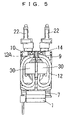
- FIG. 5 is a front view of the above-mentioned oscillation type linear actuator.
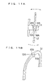
- FIG. 6A is a bottom view showing a first modification of an engaging structure of a stopper and the coupling member in the above-mentioned oscillation type linear actuator.
- FIG. 6B is a perspective view showing a shape of the stopper in the first embodiment.
- FIG. 7A is a bottom view showing a second modification of the engaging structure of the stopper and the coupling member in the above-mentioned oscillation type linear actuator.
- FIG. 7B is a perspective view showing a shape of the stopper in the second embodiment.
- FIG. 8A is a bottom view showing a third modification of the engaging structure of the stopper and the coupling member in the above-mentioned oscillation type linear actuator.
- FIG. 8B is a perspective view showing a shape of the stopper in the third embodiment.
- FIG. 9A is a bottom view showing a fourth modification of the engaging structure of the stopper and the coupling member in the above-mentioned oscillation type linear actuator.
- FIG. 9B is a perspective view showing a shape of the stopper in the fourth embodiment.
- FIG. 10A is a bottom view showing a fifth modification of the engaging structure of the stopper and the coupling member in the above-mentioned oscillation type linear actuator.
- FIG. 10B is a perspective view showing a shape of the coupling member in the fifth embodiment.
- FIG. 11A is a bottom view showing a sixth modification of the engaging structure of the stopper and the coupling member in the above-mentioned oscillation type linear actuator.
- FIG. 11B is a perspective view showing a shape of the coupling member in the sixth embodiment.
- FIG. 12A is a bottom view showing a seventh modification of the engaging structure of the stopper and the coupling member in the above-mentioned oscillation type linear actuator.
- FIG. 12B is a perspective view showing a shape of the coupling member in the seventh embodiment.
- FIG. 13A is a bottom view showing an eighth modification of the engaging structure of the stopper and the coupling member in the above-mentioned oscillation type linear actuator.
- FIG. 13B is a perspective view showing a shape of the coupling member in the eighth embodiment.
- FIG. 14 is a perspective view showing a ninth modification of the engaging structure of the stopper and the coupling member in the above-mentioned oscillation type linear actuator.
- FIG. 15 is a perspective view showing a tenth modification of the engaging structure of the stopper and the coupling member in the above-mentioned oscillation type linear actuator.
- FIG. 16 is a side view showing an eleventh modification of the engaging structure of the stopper and the coupling member in the above-mentioned oscillation type linear actuator.
- FIG. 17 is a side view showing a twelfth modification of the engaging structure of the stopper and the coupling member in the above-mentioned oscillation type linear actuator.
- FIG. 18 is a side view showing a thirteenth modification of the engaging structure of the stopper and the coupling member in the above-mentioned oscillation type linear actuator.
- FIG. 19 is a side view showing a fourteenth modification of the engaging structure of the stopper and the coupling member in the above-mentioned oscillation type linear actuator.
- FIG. 20 is a side view showing a fifteenth modification of the engaging structure of the stopper and the coupling member in the above-mentioned oscillation type linear actuator.
- FIG. 21 is a perspective view showing an installing process of the engaging structure of the stopper and the coupling member in the above-mentioned oscillation type linear actuator.
- FIG. 22 is a front view showing a sixteenth modification with respect to the coupling member in the above-mentioned oscillation type linear actuator.
- FIG. 23 is a perspective view showing a seventeenth modification with respect to the coupling member in the above-mentioned oscillation type linear actuator.
- FIG. 24 is a front view showing the shape of the coupling member in the above-mentioned seventeenth modification.
- FIG. 25A is a perspective view showing an eighteenth modification of the engaging structure of the stopper and the coupling member in the above-mentioned oscillation type linear actuator.
- FIG. 25B is a side view showing the engaging structure of the stopper and the coupling member in the above-mentioned eighteenth modification.
- FIG. 26A is a perspective view showing a nineteenth modification of the engaging structure of the stopper and the coupling member in the above-mentioned oscillation type linear actuator.
- FIG. 26B is a side view showing the engaging structure of the stopper and the coupling member in the above-mentioned nineteenth modification.
- FIG. 1 is a perspective view showing a constitution of an oscillation type linear actuator in accordance with the first embodiment
- FIG. 2 is an exploded perspective view thereof
- FIG. 3 is a front view showing a configuration of a coupling member 12 , which will be described below.
- FIG. 4 is aside view showing a constitution of a main section around the coupling member 12
- FIG. 5 is a front view thereof.
- the oscillation type linear actuator is formed for a driving source of a reciprocation type power shaver, and comprises a stator 1 , a pair of moving members 2 A and 2 B, a chassis 3 , a pair of suspenders 9 for suspending the moving members 2 A and 2 B from the chassis 3 , four coupling members 12 for coupling two moving members 2 A and 2 B, and so on.
- the stator 1 is an electromagnet in which a coil 7 is wound around a laminated body of iron plate of magnetic material or a sintered component of a magnetic material via a bobbin 6 made of resin, and fixed on the chassis 3 by screws, or the like.
- Each of the moving members 2 A and 2 B is formed integrally with a yoke 5 (back yoke) made of magnetic material by insert molding, and a permanent magnet 4 is fixed on each yoke 5 by an adhesive. Furthermore, couplers 22 , with which moving razor blades of the power shaver are respectively coupled, are provided on upper faces of arms 21 formed for protruding L-shape sidling of the moving members 2 A and 2 B.
- the chassis 3 holds the moving members 2 A and 2 B in a manner so that not only they can reciprocally move in X-direction but also the permanent magnets 4 face an upper face of the stator 1 via a predetermined gaps 8 .
- the chassis 3 is constituted by two beams 3 A in X-direction, two beams 3 B in Y-direction and four beams 3 C in Z-direction.
- Each suspensions 9 is constituted by a bridge portion 10 fixed on both end portions of the beams 3 A of the chassis 3 in X-direction, plate spring portions 9 A and lower end portions 11 which are engaged with first protrusions 23 provided at both lower end portions of the moving members 2 A and 2 B.
- Recesses 11 A, which are to be engaged with the first protrusions 23 of the moving members 2 A and 2 B, are provided on the lower end portions 11 of the suspender 9 .
- the bridge portion 10 serves as a fixing portion when the oscillation type linear actuator is assembled on a main body of the power shaver, or the like.
- the moving members 2 A and 2 B When the first protrusions 23 of the moving members 2 A and 2 B are engaged with the recesses 11 A on the lower end portions 11 of the suspenders 9 , and the bridge portions 10 of the suspenders 9 are respectively engaged with both end portions of the chassis 3 in X-direction, the moving members 2 A and 2 B are suspended in a space formed between the beams 3 A of the chassis 3 in X-direction and can be displaced in X-direction owing to warp of the plate spring portions 9 A.
- the permanent magnet 4 is fixed on one moving member 2 A in a manner so that polarity (orientation of N-pole and S-pole) thereof becomes opposite to the polarity of the permanent magnet 4 on the other moving member 2 B.
- polarity orientation of N-pole and S-pole
- absorption and objections owing to magnetic action are repeated between the stator 1 and the permanent magnets 4 .
- the moving members 2 A and 2 B repeat the reciprocal movement in opposite phases (oscillation) with each other with warping the plate spring portions 9 A, since they are respectively suspended in a manner to be able to displace in X-direction independently by the suspender 9 .
- the direction of the current applied to the coil 7 is alternated at a predetermined term in a manner so that motive forces are acted on the moving directions of the moving members 2 A and 2 B for reciprocally moving them. Furthermore, since the polarities of the permanent magnets 4 on the moving members 2 A and 2 B are opposed with each other, the moving members 2 A and 2 B respectively have phases of oscillation discrepant by 180 degrees with each other, and the vibration in the moving direction (x-direction) is reduced.
- Second protrusions 20 are respectively provided on both end portions of the moving members 2 A and 2 B in X-direction.
- the second protrusions 20 respectively protrude toward the outside of the suspenders 9 through substantially circular openings 9 B formed between the plate spring portions 9 A of the suspenders 9 .
- coupling portions 30 of the coupling members 12 are respectively engaged with the second protrusions 20 protruding outsides of the suspenders 9 .
- the coupling members 12 are used for coupling the moving members 2 A and 2 B with maintaining a state of reciprocally movable in X-direction, independently.
- the coupling member 12 has first plate spring portions 12 L and 12 R disposed symmetrical and having substantially smaller U-shape, and a second plate spring portion 12 B coupled with outer portions of respective of the first plate portions 12 L and 12 R and having substantially a larger U-shape.
- the coupling portions 30 L and 30 R are respectively formed at inner front ends of the first plate spring portions 12 L and 12 R.
- the moving members 2 A and 2 B are totally coupled with four coupling members 12 in a manner so that two of them are coupled with the second protrusions 20 at each side.
- These coupling members 12 are used for restricting the reduction of the amplitude of the reciprocal movement (oscillation) of one moving member 2 A or 2 B owing to the movement of the other moving member 2 B or 2 A, when a load applied to the moving member 2 A or 2 B is larger and the amplitude thereof is suddenly made be reduced.
- the coupling portions 30 of the coupling members 12 are respectively engaged with the second protrusions 20 provided on the end portions of the moving members 20 A and 20 B.
- the coupling portion 30 L at left hand shown in FIGS. 3 and 5 displaces perpendicularly upward with respect to the paper sheet
- the coupling portion 30 R at right hand displaces perpendicularly downward with respect to the paper sheet, and vice versa.
- each coupling member 12 can be displaced in an X-Y plane defined by X-direction and Y-direction entirely, corresponding to the reciprocal movement of the moving members 2 A and 2 B.
- the second plate spring portion 12 B it is swung on the X-Y plane around the center portion (non-displacing portion) designated by a symbol 12 A in FIG. 3 of the second plate spring portion 12 B as an axis.
- the coupling members 12 serve as springs for setting natural frequency for making the natural frequency of the moving members 2 A and 2 B constant.
- a groove 14 a of a stopper 14 fixed on the bridge portion 10 of the above-mentioned suspender 9 is engaged with the non-displacing portion 12 A of the coupling member 12 disposed, for example, at the most outward, so that side faces of the non-displacing portion 12 A of the coupling member 12 contacts with side faces of the groove 14 A of the stopper 14 .
- each coupling member 12 are not essentially restricted, but the non-displacing portion 12 A is regionally restricted, so that the non-displacing portion 12 A of the coupling member 12 cannot be displaced in the displacing direction (X-direction) of the moving members 2 A and 2 B, even when the large load is applied to only one moving member 2 A or 2 B.
- the non-displacing portion 12 A of the coupling member 12 cannot be displaced in the displacing direction (X-direction) of the moving members 2 A and 2 B, even when the large load is applied to only one moving member 2 A or 2 B.
- each coupling member 12 is constituted by combination of a plurality of substantially U-shaped plate spring portions 12 L, 12 R and 12 B, substantially entire of length of them can serve as plate spring portion.
- the length necessary for serving as the plate spring can be fit into a smaller size.
- totally four coupling members 12 are used so that two of them are respectively engaged with both end portions of the moving members 2 A and 2 B, so that stress applied to each coupling member 12 becomes smaller, and the life of the coupling member 12 can be extended.
- the groove 14 A is provided on the stopper 14 , and the non-displacing portion 12 A of the coupling member 12 is engaged with the groove 14 A of the stopper 14 .
- a rib-shaped protrusion (contacting portion) 40 is formed on each side face of the groove 14 A so that the non-displacing portion 12 A of the coupling member 12 contacts with the protrusion 40 along a line. According to the first modification, even though the shape of the stopper 14 becomes complex, friction between the coupling member 12 and the stopper 14 is reduced, so that the load resistance can be made smaller.
- each side face of the groove 14 A of the stopper 14 has two planes, and the center portion thereof is protruded so as to make the width narrower (protruded portion is designated by a symbol 40 A).
- each side face of the groove 14 A of the stopper 14 is cylindrical, and the center portion thereof is protruded so as to make the width narrower (protruded portion is designated by a symbol 40 B).
- the non-displacing portion 12 A of the coupling member 12 contacts with the protrusion 40 A or 40 B along a line, so that friction between the coupling member 12 and the stopper 14 is reduced, and the load resistance can be made smaller. Furthermore, in comparison with the first modification, rigidity of the stopper 14 can be increased.
- a hemispherical protrusion 40 C is formed on each side face of the groove 14 A of the stopper 14 , so that the non-displacing portion 12 A of the coupling member 12 contacts with the protrusion 40 C at a point.
- a contacting area of the coupling member 12 and the stopper 14 becomes much smaller, so that the friction between them can be reduced much more.
- a rib-shaped protrusion 41 is formed on each side face of the non-displacing portion 12 A of the coupling member 12 , and the protrusion 41 contacts with each side face of the groove 14 A of the stopper 14 along a line, contrary to the above-mentioned first modification.
- a sixth modification shown in FIGS. 11A and 11B corresponds to the above-mentioned second modification.
- a protrusion 41 A having two planes is formed on each side face of the non-displacing portion 12 A of the coupling member 12 , so that the protrusion 41 A contacts with each side face of the groove 14 A of the stopper 14 along a line.
- a seventh modification shown in FIGS. 12A and 12B corresponds to the above-mentioned third modification.
- a cylindrical protrusion 41 B is formed on each side face of the non-displacing portion 12 A of the coupling member 12 , so that the protrusion 41 B contacts with each side face of the groove 14 A of the stopper 14 along a line.
- FIGS. 13A and 13B corresponds to the above-mentioned fourth modification.
- a hemispherical protrusion 41 C is formed on each side face of the non-displacing portion 12 A of the coupling member 12 , so that the protrusion 41 C contacts with each side face of the groove 14 A of the stopper 14 at a point.
- a rotation shaft 43 is formed on the non-displacing portion 12 A of the coupling member 12 , and a bearing 44 is formed on the stopper 14 , so that the coupling member 12 is rotatably borne by engagement of the rotation shaft 43 with the bearing 44 .
- a bearing 46 is formed on the non-displacing portion 12 A of the coupling member 12
- a rotation shaft 45 is formed on the stopper 14 , so that the coupling member 12 is rotatably borne by engagement of the rotation shaft 45 with the bearing 46 .
- the motion of the coupling member 12 can be made much smoother.
- the rotation shafts 43 and 45 are respectively formed integrally with the coupling member 12 and the stopper 14 by resin molding.
- the rotation shafts 43 and 45 are respectively formed by metal, and they are fitted to or integrally formed by insert molding with the coupling member 12 or the stopper 14 made of resin.
- one groove 14 or bearing 44 is formed on one stopper 14 so as to be engaged with one coupling member 12 .
- This invention is not limited these examples. It is possible to form the grooves 14 or the bearings 44 having substantially the same shapes at two positions on the same stopper, so that two coupling members 12 are engaged with them.
- FIG. 16 it is configured that an outer face 12 e of an outer coupling member 12 E and an inner face 12 f of an inner coupling member 12 F respectively contact with both side faces of one groove 14 A formed on one stopper 14 .
- a wall 14 B is formed at an outer end of the stopper 14 instead of the groove, and only the outer face 12 e of the outer coupling member 12 E contacts with the wall 14 B.
- a wall 14 C is formed at an inner end of the stopper 14 , and only the inner face 12 f of the inner coupling member 12 F contacts with the wall 14 C.
- an inner face of the outer coupling member 12 E and an outer face of the inner coupling member 12 F respectively contact with both faces of a wall 14 D, like a fourteenth modification shown in FIG. 19 . It is possible to provide the stopper 14 only at one side, so that positioning restriction is carried out with respect to the non-displacing portions 12 A of the coupling members 12 disposed at the same side, like a fifteenth modification shown in FIG. 20 .
- stoppers 14 are adhered on end faces 10 A of the bridge portions 10 of the suspenders 9 , after the coupling portions 30 of the coupling members 121 are engaged with and fixed on the second protrusions 20 of the moving members 2 A and 2 B.
- fixing positions of the stoppers 14 can be adjusted corresponding to the positions of the non-displacing portions 12 A of the coupling members 12 , so that the positioning restriction of the non-displacing portions 12 A of the coupling members 12 can surely be carried out.
- the coupling member 12 is constituted as line symmetry with respect to the non-displacing portion 12 A, the non-displacing portion 12 A of the coupling member 12 is positioned substantially at the center of two moving members 2 A and 2 B, and the stopper 14 is provided substantially at the center of two moving members 2 A and 2 B.
- the stopper 14 is fitted within a width of the oscillation type linear actuator owing to the stopper 14 is fixed on the bridge portion 10 of the suspender 9 .
- the coupling member 12 is formed asymmetrical, so that the non-displacing portion 12 A and the stopper 14 are positioned at a side of the oscillation type linear actuator.
- the shape of the coupling member 12 is designed in a manner so that a length from the non-displacing portion 12 A to the coupling portion 30 L at left hand is substantially equal to a length from the non-displacing portion 12 A to the coupling portion 30 R at right hand. In this case, even though the width of the oscillation type linear actuator becomes a little wider due to the stopper 14 , a height at both ends of the oscillation type linear actuator where the coupling members 12 are provided can be made lower.
- the coupling member 12 is constituted point symmetrical with respect to the non-displacing portion 12 A, so that the coupling member 12 is formed substantially S-shape.
- the non-displacing portion 12 A and the stopper 14 are positioned substantially at the center on a front face of the oscillation type linear actuator, it is possible to make the height and the width of the oscillation type linear actuator smaller.
- the stopper 14 is provided at a position where the coupling portions 30 L and 30 R are disposed in FIGS. 3 and 5 , it is necessary to change shapes and positions of coupling portions 31 which are coupled with the moving members 2 A and 2 B.
- arms 12 n are extended inward from end portions 12 m of a section having substantially S-shape, and the coupling portions 31 are formed by bending end portions of the extended arms 12 n towards the moving members 2 A and 2 B.
- the stopper 14 is shaped to support the coupling member 12 at a lower end thereof (at a side of the stator 1 ) for restricting the motion of the coupling member 12 in a direction of absorption between the stator 1 and the moving members 2 A and 2 B (downward in Z-direction).
- the stopper 14 since dimensions of the gaps 8 between the upper face of the stator 1 and the permanent magnets 4 on the moving members 2 A and 2 B can be maintained, it is possible to omit the suspenders 9 .
- the stopper 14 is shaped to support the coupling member 12 at an upper end thereof too (at the opposite side of the stator 1 ) for restricting the motion of the coupling member 12 in a direction of objection between the stator 1 and the moving members 2 A and 2 B (upward in Z-direction), further to the above-mentioned constitution.
- resistance to the impact at the case of dropping, or the like can be increased in addition to the above-mentioned effects.
- the oscillation type linear actuator using two moving members which is suitable for reciprocation type power shaver, is described. It is sufficient that a plurality of moving members is used, and it is not limited to two. Furthermore, since the use of the oscillation type linear actuator is not limited to the reciprocation type power shaver, it is possible to be used in other many apparatuses as a driving source thereof.
Landscapes
- Engineering & Computer Science (AREA)
- Life Sciences & Earth Sciences (AREA)
- Forests & Forestry (AREA)
- Mechanical Engineering (AREA)
- Power Engineering (AREA)
- Reciprocating, Oscillating Or Vibrating Motors (AREA)
- Dry Shavers And Clippers (AREA)
Abstract
Description
Claims (13)
Applications Claiming Priority (3)
| Application Number | Priority Date | Filing Date | Title |
|---|---|---|---|
| JP2002-176466 | 2002-06-17 | ||
| JP2002176466A JP3928495B2 (en) | 2002-06-17 | 2002-06-17 | Vibration type linear actuator |
| PCT/JP2003/007696 WO2003107516A1 (en) | 2002-06-17 | 2003-06-17 | Vibration type linear actuator |
Publications (2)
| Publication Number | Publication Date |
|---|---|
| US20050173662A1 US20050173662A1 (en) | 2005-08-11 |
| US6991217B2 true US6991217B2 (en) | 2006-01-31 |
Family
ID=29728093
Family Applications (1)
| Application Number | Title | Priority Date | Filing Date |
|---|---|---|---|
| US10/508,707 Expired - Fee Related US6991217B2 (en) | 2002-06-17 | 2003-06-17 | Vibration type linear actuator |
Country Status (7)
| Country | Link |
|---|---|
| US (1) | US6991217B2 (en) |
| EP (1) | EP1515420B1 (en) |
| JP (1) | JP3928495B2 (en) |
| KR (1) | KR100671849B1 (en) |
| CN (1) | CN1647350B (en) |
| AU (1) | AU2003244238A1 (en) |
| WO (1) | WO2003107516A1 (en) |
Cited By (22)
| Publication number | Priority date | Publication date | Assignee | Title |
|---|---|---|---|---|
| US20050140219A1 (en) * | 2003-12-26 | 2005-06-30 | Wataru Sanematsu | Linear oscillating actuator |
| US20060021227A1 (en) * | 2004-07-30 | 2006-02-02 | Matsushita Electric Works, Ltd. | Reciprocatory dry shaver |
| US20060158048A1 (en) * | 2005-01-19 | 2006-07-20 | Matsushita Electric Works, Ltd. | Vibratory linear actuator and electric toothbrush using the same |
| US20090096296A1 (en) * | 2007-10-12 | 2009-04-16 | Roger Mark | Relieving stress in a flexure |
| US20090165305A1 (en) * | 2006-07-20 | 2009-07-02 | Bernhard Kraus | Electric Shaving Apparatus |
| US20090267422A1 (en) * | 2008-04-24 | 2009-10-29 | Panasonic Electric Works Co., Ltd. | Vibratory linear actuator |
| US20100175264A1 (en) * | 2009-01-15 | 2010-07-15 | Panasonic Electric Works Co., Ltd. | Electric shaver |
| US20100213773A1 (en) * | 2009-02-20 | 2010-08-26 | Aac Acoustic Technologies (Shenzhen) Co., Ltd | Linear Vibrator |
| US20100327673A1 (en) * | 2009-05-25 | 2010-12-30 | Jae-Woo Jun | Linear vibrator |
| US20110001365A1 (en) * | 2009-07-01 | 2011-01-06 | Park Seok Jun | Linear vibration motor |
| US20110006618A1 (en) * | 2009-07-07 | 2011-01-13 | Samsung Electro-Mechanics Co., Ltd. | Vibration motor |
| US20120074796A1 (en) * | 2010-09-27 | 2012-03-29 | Panasonic Electric Works Co., Ltd. | Linear oscillatory actuator |
| US20120151773A1 (en) * | 2009-09-25 | 2012-06-21 | Panasonic Corporation | Electric shaver |
| US9496778B2 (en) | 2012-08-22 | 2016-11-15 | Ta Instruments-Waters L.L.C. | Electromagnetic motor |
| US9993930B2 (en) | 2014-12-23 | 2018-06-12 | Braun Gmbh | Electric appliance for personal care |
| US20180304481A1 (en) * | 2017-04-19 | 2018-10-25 | Panasonic Intellectual Property Management Co., Ltd. | Oscillatory linear actuator and cutting device |
| US20200358346A1 (en) * | 2017-12-05 | 2020-11-12 | Ams R&D Sas | Electric motor |
| US20200360123A1 (en) * | 2017-12-27 | 2020-11-19 | Guangzhou Chili Technology Co., Ltd. | Swing motor and electric device |
| US20230198363A1 (en) * | 2021-12-16 | 2023-06-22 | Guangdong Huida Electric Appliance Co. LTD | Brushless electromagnetic suspension vibration motor |
| US11967881B1 (en) * | 2023-02-28 | 2024-04-23 | Danxiao Information Tech Ltd. | Magnetometric transmission structure and an oscillating device with pressure chamber |
| US20250350165A1 (en) * | 2025-04-08 | 2025-11-13 | Dongguan Chi Drive Motors Co.,Ltd | Support structure for linear motor |
| US12533822B2 (en) | 2020-06-11 | 2026-01-27 | Andis Company | Hair clipper with linear actuator |
Families Citing this family (14)
| Publication number | Priority date | Publication date | Assignee | Title |
|---|---|---|---|---|
| KR101070377B1 (en) * | 2009-09-29 | 2011-10-06 | 삼성전기주식회사 | vibration motor |
| KR101022899B1 (en) * | 2009-10-06 | 2011-03-16 | 삼성전기주식회사 | Horizontal linear oscillator |
| JP5453188B2 (en) * | 2010-07-08 | 2014-03-26 | パナソニック株式会社 | Reciprocating electric razor |
| JP5513288B2 (en) * | 2010-07-08 | 2014-06-04 | パナソニック株式会社 | Reciprocating electric razor |
| JP2012016491A (en) * | 2010-07-08 | 2012-01-26 | Panasonic Electric Works Co Ltd | Reciprocating electric shaver |
| JP5396342B2 (en) * | 2010-07-08 | 2014-01-22 | パナソニック株式会社 | Reciprocating electric razor |
| CN102545526B (en) * | 2010-12-20 | 2016-01-06 | 德昌电机(深圳)有限公司 | Actuator |
| US9590463B2 (en) | 2011-09-22 | 2017-03-07 | Minebea Co., Ltd. | Vibration generator moving vibrator by magnetic field generated by coil and holder used in vibration-generator |
| JP5844103B2 (en) * | 2011-09-22 | 2016-01-13 | ミネベア株式会社 | Vibration generator |
| KR200464536Y1 (en) * | 2011-11-02 | 2013-01-08 | 대성전기공업 주식회사 | Rotational actuator |
| CN102642213B (en) * | 2012-05-10 | 2014-08-06 | 浙江海顺电工有限公司 | Shaver and cutter head device of shaver |
| JP6029854B2 (en) | 2012-05-22 | 2016-11-24 | ミネベア株式会社 | Vibrator and vibration generator |
| JP6121173B2 (en) | 2013-01-22 | 2017-04-26 | ミネベアミツミ株式会社 | Holder with vibrator and vibration generator |
| EP3403778B1 (en) * | 2017-05-17 | 2020-01-01 | Panasonic Intellectual Property Management Co., Ltd. | Hair cutting device |
Citations (11)
| Publication number | Priority date | Publication date | Assignee | Title |
|---|---|---|---|---|
| US3906263A (en) * | 1974-05-23 | 1975-09-16 | Sperry Rand Corp | Vibrator motor in hand-held electric appliance |
| US4326138A (en) * | 1979-02-08 | 1982-04-20 | Yeda Research & Development Co., Ltd. | Hair cutting apparatus |
| US4583027A (en) * | 1982-12-27 | 1986-04-15 | Hitachi Metals International, Ltd. | Moving magnet linear motor |
| WO1996037347A1 (en) | 1995-05-26 | 1996-11-28 | Matsushita Electric Works, Ltd. | Vibratory linear actuator and method of driving the same |
| US5632087A (en) * | 1994-03-28 | 1997-05-27 | Matsushita Electric Works, Ltd. | Reciprocatory dry shaver |
| US5736797A (en) * | 1995-05-31 | 1998-04-07 | Matsushita Electric Works, Ltd. | Linear oscillating motor |
| US5886601A (en) | 1997-02-06 | 1999-03-23 | Matsushita Electric Works, Ltd. | Electromagnetic relay assembly |
| JPH11136921A (en) | 1997-10-28 | 1999-05-21 | Matsushita Electric Works Ltd | Vibration-type linear actuator |
| JPH11285226A (en) | 1998-03-26 | 1999-10-15 | Matsushita Electric Works Ltd | Oscillation type linear actuator |
| EP1162721A2 (en) | 2000-06-07 | 2001-12-12 | Matsushita Electric Works, Ltd. | Linear oscillating actuator |
| US6441517B1 (en) * | 1998-12-23 | 2002-08-27 | Braun Gmbh | Drive mechanism for oscillating electric products of personal use, particularly dry shavers |
Family Cites Families (2)
| Publication number | Priority date | Publication date | Assignee | Title |
|---|---|---|---|---|
| JPS59176382U (en) * | 1983-05-12 | 1984-11-26 | 御器谷 俊雄 | Reciprocating rod holding device for electromagnetic reciprocating motor |
| JP3661369B2 (en) * | 1997-10-28 | 2005-06-15 | 松下電工株式会社 | Vibration type linear actuator |
-
2002
- 2002-06-17 JP JP2002176466A patent/JP3928495B2/en not_active Expired - Fee Related
-
2003
- 2003-06-17 AU AU2003244238A patent/AU2003244238A1/en not_active Abandoned
- 2003-06-17 EP EP03760163A patent/EP1515420B1/en not_active Expired - Lifetime
- 2003-06-17 KR KR1020047015518A patent/KR100671849B1/en not_active Expired - Fee Related
- 2003-06-17 WO PCT/JP2003/007696 patent/WO2003107516A1/en not_active Ceased
- 2003-06-17 CN CN03807561XA patent/CN1647350B/en not_active Expired - Fee Related
- 2003-06-17 US US10/508,707 patent/US6991217B2/en not_active Expired - Fee Related
Patent Citations (14)
| Publication number | Priority date | Publication date | Assignee | Title |
|---|---|---|---|---|
| US3906263A (en) * | 1974-05-23 | 1975-09-16 | Sperry Rand Corp | Vibrator motor in hand-held electric appliance |
| US4326138A (en) * | 1979-02-08 | 1982-04-20 | Yeda Research & Development Co., Ltd. | Hair cutting apparatus |
| US4583027A (en) * | 1982-12-27 | 1986-04-15 | Hitachi Metals International, Ltd. | Moving magnet linear motor |
| US5632087A (en) * | 1994-03-28 | 1997-05-27 | Matsushita Electric Works, Ltd. | Reciprocatory dry shaver |
| US5921134A (en) | 1995-05-26 | 1999-07-13 | Matsushita Electric Works, Ltd. | Vibratory linear actuator and method of driving the same |
| JPH08318061A (en) | 1995-05-26 | 1996-12-03 | Matsushita Electric Works Ltd | Vibration type linear actuator |
| WO1996037347A1 (en) | 1995-05-26 | 1996-11-28 | Matsushita Electric Works, Ltd. | Vibratory linear actuator and method of driving the same |
| US5736797A (en) * | 1995-05-31 | 1998-04-07 | Matsushita Electric Works, Ltd. | Linear oscillating motor |
| US5886601A (en) | 1997-02-06 | 1999-03-23 | Matsushita Electric Works, Ltd. | Electromagnetic relay assembly |
| JPH11136921A (en) | 1997-10-28 | 1999-05-21 | Matsushita Electric Works Ltd | Vibration-type linear actuator |
| JPH11285226A (en) | 1998-03-26 | 1999-10-15 | Matsushita Electric Works Ltd | Oscillation type linear actuator |
| US6441517B1 (en) * | 1998-12-23 | 2002-08-27 | Braun Gmbh | Drive mechanism for oscillating electric products of personal use, particularly dry shavers |
| EP1162721A2 (en) | 2000-06-07 | 2001-12-12 | Matsushita Electric Works, Ltd. | Linear oscillating actuator |
| US6559563B1 (en) * | 2000-06-07 | 2003-05-06 | Matsushita Electric Works, Ltd. | Linear oscillating actuator |
Non-Patent Citations (3)
| Title |
|---|
| English Language Abstract of JP 11-136921. |
| English Language Abstract of JP 11-285226. |
| English Language Abstract of JP 8-318061. |
Cited By (44)
| Publication number | Priority date | Publication date | Assignee | Title |
|---|---|---|---|---|
| US7304407B2 (en) * | 2003-12-26 | 2007-12-04 | Matsushita Electric Works, Ltd. | Linear oscillating actuator |
| US20050140219A1 (en) * | 2003-12-26 | 2005-06-30 | Wataru Sanematsu | Linear oscillating actuator |
| US20060021227A1 (en) * | 2004-07-30 | 2006-02-02 | Matsushita Electric Works, Ltd. | Reciprocatory dry shaver |
| US7334338B2 (en) * | 2004-07-30 | 2008-02-26 | Matsushita Electric Works, Ltd. | Reciprocatory dry shaver |
| US20060158048A1 (en) * | 2005-01-19 | 2006-07-20 | Matsushita Electric Works, Ltd. | Vibratory linear actuator and electric toothbrush using the same |
| US7495358B2 (en) * | 2005-01-19 | 2009-02-24 | Panasonic Electric Works Co., Ltd. | Vibratory linear actuator and electric toothbrush using the same |
| US8806756B2 (en) * | 2006-07-20 | 2014-08-19 | Braun Gmbh | Electric shaving apparatus |
| US20090165305A1 (en) * | 2006-07-20 | 2009-07-02 | Bernhard Kraus | Electric Shaving Apparatus |
| US20090096296A1 (en) * | 2007-10-12 | 2009-04-16 | Roger Mark | Relieving stress in a flexure |
| US7679229B2 (en) * | 2007-10-12 | 2010-03-16 | Bose Corporation | Relieving stress in a flexure |
| US20090267422A1 (en) * | 2008-04-24 | 2009-10-29 | Panasonic Electric Works Co., Ltd. | Vibratory linear actuator |
| US7965000B2 (en) * | 2008-04-24 | 2011-06-21 | Panasonic Electric Works Co., Ltd. | Vibratory linear actuator |
| US9399302B2 (en) | 2009-01-15 | 2016-07-26 | Panasonic Intellectual Property Management Co., Ltd. | Electric shaver |
| US20100175264A1 (en) * | 2009-01-15 | 2010-07-15 | Panasonic Electric Works Co., Ltd. | Electric shaver |
| US8627574B2 (en) * | 2009-01-15 | 2014-01-14 | Panasonic Corporation | Electric shaver |
| US20100213773A1 (en) * | 2009-02-20 | 2010-08-26 | Aac Acoustic Technologies (Shenzhen) Co., Ltd | Linear Vibrator |
| US8334624B2 (en) * | 2009-02-20 | 2012-12-18 | Aac Acoustic Technologies (Shenzhen) Co., Ltd. | Horizontal linear vibrator |
| US20100327673A1 (en) * | 2009-05-25 | 2010-12-30 | Jae-Woo Jun | Linear vibrator |
| US8288898B2 (en) * | 2009-05-25 | 2012-10-16 | Samsung Electro-Mechanics Co., Ltd. | Linear vibrator having plate-shaped springs |
| US8188623B2 (en) * | 2009-07-01 | 2012-05-29 | Samsung Electro-Mechanics Co., Ltd. | Linear vibration motor |
| US20110001365A1 (en) * | 2009-07-01 | 2011-01-06 | Park Seok Jun | Linear vibration motor |
| US7911098B2 (en) * | 2009-07-07 | 2011-03-22 | Samsung Electro-Mechanics Co., Ltd. | Vibration motor |
| US20110006618A1 (en) * | 2009-07-07 | 2011-01-13 | Samsung Electro-Mechanics Co., Ltd. | Vibration motor |
| CN101944818B (en) * | 2009-07-07 | 2014-06-04 | 三星电机株式会社 | Linear vibrator |
| US20120151773A1 (en) * | 2009-09-25 | 2012-06-21 | Panasonic Corporation | Electric shaver |
| US9527219B2 (en) * | 2009-09-25 | 2016-12-27 | Panasonic Intellectual Property Management Co., Ltd. | Electric shaver |
| US8373315B2 (en) * | 2010-09-27 | 2013-02-12 | Panasonic Corporation | Linear oscillatory actuator |
| US20120074796A1 (en) * | 2010-09-27 | 2012-03-29 | Panasonic Electric Works Co., Ltd. | Linear oscillatory actuator |
| US9496778B2 (en) | 2012-08-22 | 2016-11-15 | Ta Instruments-Waters L.L.C. | Electromagnetic motor |
| US9768675B2 (en) | 2012-08-22 | 2017-09-19 | Ta Instruments-Waters L.L.C. | Electromagnetic motor |
| US9993930B2 (en) | 2014-12-23 | 2018-06-12 | Braun Gmbh | Electric appliance for personal care |
| US10035273B2 (en) | 2014-12-23 | 2018-07-31 | Braun Gmbh | Electric appliance for personal care |
| US11235481B2 (en) * | 2017-04-19 | 2022-02-01 | Panasonic Intellectual Property Management Co., Ltd. | Oscillatory linear actuator and cutting device |
| US20180304481A1 (en) * | 2017-04-19 | 2018-10-25 | Panasonic Intellectual Property Management Co., Ltd. | Oscillatory linear actuator and cutting device |
| US20200358346A1 (en) * | 2017-12-05 | 2020-11-12 | Ams R&D Sas | Electric motor |
| US11791702B2 (en) * | 2017-12-05 | 2023-10-17 | Ams R&D Sas | Electric motor with stator and mobile armature with suspending leaf springs which prevent movement in transverse direction and is in airgap plane that is perpendicular to first loop plane |
| US20200360123A1 (en) * | 2017-12-27 | 2020-11-19 | Guangzhou Chili Technology Co., Ltd. | Swing motor and electric device |
| US11646650B2 (en) * | 2017-12-27 | 2023-05-09 | Guangzhou Chili Technology Co., Ltd. | Swing motor with two movable members having elastic support members and torsion elastic members |
| US12533822B2 (en) | 2020-06-11 | 2026-01-27 | Andis Company | Hair clipper with linear actuator |
| US20230198363A1 (en) * | 2021-12-16 | 2023-06-22 | Guangdong Huida Electric Appliance Co. LTD | Brushless electromagnetic suspension vibration motor |
| US12278536B2 (en) * | 2021-12-16 | 2025-04-15 | Guangdong Huida Electric Appliance Co. LTD | Brushless electromagnetic suspension vibration motor with swing rods and elastic pieces |
| US11967881B1 (en) * | 2023-02-28 | 2024-04-23 | Danxiao Information Tech Ltd. | Magnetometric transmission structure and an oscillating device with pressure chamber |
| US20250350165A1 (en) * | 2025-04-08 | 2025-11-13 | Dongguan Chi Drive Motors Co.,Ltd | Support structure for linear motor |
| US12556057B2 (en) * | 2025-04-08 | 2026-02-17 | Dongguan Chi Drive Motors co., LTD | Support structure for linear motor |
Also Published As
| Publication number | Publication date |
|---|---|
| JP2004023909A (en) | 2004-01-22 |
| AU2003244238A1 (en) | 2003-12-31 |
| KR100671849B1 (en) | 2007-01-19 |
| WO2003107516A1 (en) | 2003-12-24 |
| CN1647350B (en) | 2011-06-01 |
| JP3928495B2 (en) | 2007-06-13 |
| US20050173662A1 (en) | 2005-08-11 |
| EP1515420A1 (en) | 2005-03-16 |
| EP1515420A4 (en) | 2007-12-26 |
| CN1647350A (en) | 2005-07-27 |
| EP1515420B1 (en) | 2012-06-06 |
| KR20050002914A (en) | 2005-01-10 |
Similar Documents
| Publication | Publication Date | Title |
|---|---|---|
| US6991217B2 (en) | Vibration type linear actuator | |
| CN110875680B (en) | Vibration actuator and portable electronic device provided with same | |
| EP3442103B1 (en) | Linear oscillatory actuator | |
| EP3252935B1 (en) | Implement for personal cleaning and care | |
| US7015602B2 (en) | Small electric appliance with a drive mechanism for generating an oscillatory motion | |
| US5444313A (en) | Electromagnetic actuator having two opposite phase movable parts | |
| EP1566879A1 (en) | Actuator | |
| EP1439630B1 (en) | Reciprocating linear actuator | |
| US7504751B2 (en) | Small electric appliance with a drive mechanism for generating an oscillatory motion | |
| JP4679902B2 (en) | Small electric appliance with drive mechanism for generating oscillating motion | |
| CN117858768A (en) | Vibration actuator | |
| KR100543098B1 (en) | Linear Oscillating Actuator | |
| CN107431425B (en) | Linear Vibration Motor | |
| JP2012110150A (en) | Vibration type linear actuator | |
| JP2013247810A (en) | Vibration actuator | |
| KR101027215B1 (en) | Vibration Type Linear Actuator | |
| JP2012070578A (en) | Vibration type linear actuator | |
| CN116760254A (en) | Vibration motors and electronics |
Legal Events
| Date | Code | Title | Description |
|---|---|---|---|
| AS | Assignment |
Owner name: MATSUSHITA ELECTRIC WORKS, LTD., JAPAN Free format text: ASSIGNMENT OF ASSIGNORS INTEREST;ASSIGNORS:SHIMIZU, HIROAKI;YABUUCHI, HIDEKAZU;MORIGUCHI, MASASHI;AND OTHERS;REEL/FRAME:016531/0048 Effective date: 20040921 |
|
| FEPP | Fee payment procedure |
Free format text: PAYOR NUMBER ASSIGNED (ORIGINAL EVENT CODE: ASPN); ENTITY STATUS OF PATENT OWNER: LARGE ENTITY |
|
| AS | Assignment |
Owner name: PANASONIC ELECTRIC WORKS CO., LTD., JAPAN Free format text: CHANGE OF NAME;ASSIGNOR:MATSUSHITA ELECTRIC WORKS, LTD.;REEL/FRAME:022191/0478 Effective date: 20081001 Owner name: PANASONIC ELECTRIC WORKS CO., LTD.,JAPAN Free format text: CHANGE OF NAME;ASSIGNOR:MATSUSHITA ELECTRIC WORKS, LTD.;REEL/FRAME:022191/0478 Effective date: 20081001 |
|
| FPAY | Fee payment |
Year of fee payment: 4 |
|
| REMI | Maintenance fee reminder mailed | ||
| LAPS | Lapse for failure to pay maintenance fees | ||
| STCH | Information on status: patent discontinuation |
Free format text: PATENT EXPIRED DUE TO NONPAYMENT OF MAINTENANCE FEES UNDER 37 CFR 1.362 |
|
| STCH | Information on status: patent discontinuation |
Free format text: PATENT EXPIRED DUE TO NONPAYMENT OF MAINTENANCE FEES UNDER 37 CFR 1.362 |
|
| FP | Lapsed due to failure to pay maintenance fee |
Effective date: 20140131 |