US6975673B1 - Narrow-band interference rejecting spread spectrum radio system and method - Google Patents
Narrow-band interference rejecting spread spectrum radio system and method Download PDFInfo
- Publication number
- US6975673B1 US6975673B1 US09/720,270 US72027001A US6975673B1 US 6975673 B1 US6975673 B1 US 6975673B1 US 72027001 A US72027001 A US 72027001A US 6975673 B1 US6975673 B1 US 6975673B1
- Authority
- US
- United States
- Prior art keywords
- code
- signal
- receiver
- narrow
- excised
- Prior art date
- Legal status (The legal status is an assumption and is not a legal conclusion. Google has not performed a legal analysis and makes no representation as to the accuracy of the status listed.)
- Expired - Lifetime
Links
Images


Classifications
-
- H—ELECTRICITY
- H04—ELECTRIC COMMUNICATION TECHNIQUE
- H04K—SECRET COMMUNICATION; JAMMING OF COMMUNICATION
- H04K3/00—Jamming of communication; Counter-measures
- H04K3/20—Countermeasures against jamming
- H04K3/22—Countermeasures against jamming including jamming detection and monitoring
- H04K3/224—Countermeasures against jamming including jamming detection and monitoring with countermeasures at transmission and/or reception of the jammed signal, e.g. stopping operation of transmitter or receiver, nulling or enhancing transmitted power in direction of or at frequency of jammer
- H04K3/228—Elimination in the received signal of jamming or of data corrupted by jamming
-
- H—ELECTRICITY
- H04—ELECTRIC COMMUNICATION TECHNIQUE
- H04B—TRANSMISSION
- H04B1/00—Details of transmission systems, not covered by a single one of groups H04B3/00 - H04B13/00; Details of transmission systems not characterised by the medium used for transmission
- H04B1/69—Spread spectrum techniques
- H04B1/707—Spread spectrum techniques using direct sequence modulation
- H04B1/7097—Interference-related aspects
- H04B1/71—Interference-related aspects the interference being narrowband interference
- H04B1/7102—Interference-related aspects the interference being narrowband interference with transform to frequency domain
Definitions
- the present invention relates to communications-related systems and methods as well as digital signal processing devices and methods. More particularly, the invention is directed to the field of spread spectrum (SS) communication that employs a SS transmitter and a SS receiver, or SS transceiver configured to convey a message in a transmitted SS signal by spectrally spreading the message signal on transmission and correlating on reception so as to “despread” the SS signal and recover the message signal.
- SS spread spectrum
- Spread spectrum radio communication addresses the shortcomings of narrowband radio communications by combining a wideband spreading signal with the message signal so as to spectrally spread the message signal.
- the transmitter also modulates an RF carrier with a message, as with the narrowband systems, but then adds one more step by modulating the resulting signal with a wideband, noise-like spreading signal (e.g. a PN code). Consequently, the message signal is spread in frequency over a much larger bandwidth, typically by ten to a thousand fold.
- Common spread spectrum techniques include frequency hopping and direct sequence. Frequency hopping systems drive (i.e., “hop”) the message modulated carrier to frequencies following a pseudo-random pattern defined by a spreading code.
- Direct sequence systems combine a spreading code with the message modulated carrier to create a signal which occupies about the bandwidth of the spreading signal.
- Narrowband interference signals transmitted at the same frequency as a portion of the desired spread signal “jam” the spread signal by an amount proportional to the ratio of jammer bandwidth to spread bandwidth.
- the narrowband interfering signal is attenuated by a “process gain” of the spread spectrum system, where process gain is defined as a ratio of spread signal bandwidth to message signal bandwidth.
- process gain is defined as a ratio of spread signal bandwidth to message signal bandwidth.
- spread spectrum signals also offer some degree of immunity to multipath fading and distortions.
- the process gain of the system may be insufficient to overcome the undesirable effects of a nearby narrowband jammer.
- a narrow band-reject filter placed prior to the spread spectrum correlator provides narrowband interference rejection far in excess of the process gain.
- Applications are enabled where a distant SS transmitter is received by a SS receiver in the presence of a nearby narrowband jammer.
- Many techniques have been disclosed which practice the narrow band-reject filter. Some are accomplished in the frequency domain with digital signal processing (DSP). These techniques as taught require extensive computing resources and are therefor relatively expensive to implement.
- DSP digital signal processing
- Souissi (U.S. Pat. No. 5,671,247) teaches a frequency domain technique to remove narrowband jammers from a received spread spectrum signal. Souissi converts a received signal into the frequency domain where the signal components are represented by magnitude and phase. The magnitude of all signal components are normalized, thereby reducing the effects of narrowband jammers. The resultant signal components are then converted back into the time domain for message demodulation.
- Blanchard U.S. Pat. No. 5,612,978 also teaches the use of frequency domain techniques to reject narrowband interference. Frequency bins in which narrowband energy is detected are removed. The circuit contains a delay element to account for the time required for the FFT processing. It also requires the use of noise estimation for proper operation.
- a general digital signal processing reference is “Handbook for Digital Signal Processing” by Sanjit K. Mitra and James F. Kaiser, 1993, John Wiley & Sons, Inc.
- Another object of this invention is to provide a novel spread spectrum receiver and method which rejects narrow-band interference during spreading code synchronization and message demodulation.
- a further object of this invention is to provide a novel spread spectrum receiver and method which provides relatively rapid spreading code synchronization.
- Yet another object of this invention is to provide a novel spread spectrum receiver and method which provides full process gain and receive sensitivity with relatively low accuracy frequency sources in a transmitter and a receiver.
- Another object of this invention is to provide a novel spread spectrum receiver and method which is computationally efficient when practiced on a digital signal processor, i.e., requires relatively a reduced amount of hardware and/or software.
- Still a further object of this invention is to provide a novel spread spectrum receiver and method which may band-limit the received signal to reject out of band interference and/or which also may downconvert the received signal from a near-baseband intermediate frequency (IF) to baseband.
- IF intermediate frequency
- a new and improved spread spectrum radio receiver and method for narrow-band interference rejection in a received signal transmitted by a spread spectrum transmitter including transforming the received signal to a frequency domain signal and identifying narrow-band interference components in the frequency domain signal; suppressing the identified narrow-band interference components by excising the identified narrow-band interference components from the frequency domain signal to produce an interference excised signal in the frequency domain, and storing in a memory frequencies corresponding to the identified narrow-band interference components; synchronizing a receiver code to a transmitter code in the frequency domain using the interference excised signal; generating coefficients for a time domain filter that includes notches at the frequencies corresponding to the excised narrow-band interference components and that jointly despreads and rejects narrow-band interference from said excised frequencies; applying the coefficients generated in the preceding step to the time domain filter; and despreading and filtering in real time in the time domain the received signal using the applied coefficients.
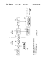
- FIGS. 1A and 1B are diagrams of a spread spectrum radio transmitting and receiving system that rejects narrow-band interference.
- FIGS. 2 , 13 and 14 are diagrams of synchronization and demodulation methods that reject narrow-band interference in a spread spectrum radio receiver.
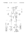
- FIGS. 3 , 5 , 6 and 7 are diagrams of frequency domain synchronization methods that reject narrow-band interference in a spread spectrum radio receiver.
- FIG. 4 is a diagram of a frequency domain narrow-band interference rejection method in a spread spectrum radio receiver.
- FIGS. 8 through 11 are diagrams of frequency domain to time domain conversion methods that reject narrow-band interference in a spread spectrum radio receiver.
- FIG. 12 is a diagram of a time domain despreading method that rejects narrow-band interference in a spread spectrum radio receiver.
- FIGS. 15 through 18 are diagrams of frequency domain despreading methods that reject narrow-band interference in a spread spectrum radio receiver.
- the present invention resolves both frequency difference between a receiver and a transmitter and the spreading code delay (time difference) between a receiver and a transmitter.
- a transmitter is shown in FIG. 1A where a carrier wave generated by a frequency source 102 is modulated 104 by a message 106 . The resultant signal is then modulated 108 by a spreading code 110 to achieve the benefits of spread spectrum communications. This signal is then amplified at amplifier 112 prior to transmission via antenna 114 . Frequency source 102 will generate the carrier wave as well as control the timing of both the message 106 and the timing of the spreading code generator 110 .
- the spread spectrum transmitter that works in conjunction with the receiver in the preferred embodiment of the present invention has a crystal controlled frequency source. This invention enables an inexpensive transmitter frequency source having an accuracy of ⁇ 50 parts per million (ppm) in the preferred embodiment.
- the receiver of the present invention is shown in FIG. 1B where diversity antennas 120 and 122 (and, alternately, additional antennas) provide an RF signal to analog front-end 124 .
- This front end may convert the RF signal either to an intermediate frequency (IF) signal or directly to baseband.
- the downconverted signal is digitized at the analog to digital converter (ADC) 126 .
- the digitized signal is sent to the digital signal processing (DSP) section 128 .
- Frequency source 130 provides one or more downconversion frequencies to the analog front end 124 , a sampling clock to ADC 126 , and a processor clock to DSP 128 .
- the receiver in the preferred embodiment of the present invention has a crystal controlled frequency source with an accuracy of ⁇ 15 ppm.
- the total system frequency error is the sum of the errors from both the transmitter and the receiver.
- the overall frequency accuracy of the system in the preferred embodiment is about ⁇ 65 ppm.
- the center frequency of the transmitted signal is about 915 MHz.
- the receiver must be able to resolve a signal with about ⁇ 60 kHz of frequency error.
- the present invention is not dependent on a particular method of message (information) modulation.
- the in-phase (I) and quadrature (Q) values of the message symbols in the following disclosure may represent any analog (AM, PM, FM or other) or digital (ASK, PSK, FSK, QAM or other) information modulation method.
- the present invention is directed to the digital signal processing portion of a spread spectrum receiver.
- DSP digital signal processor
- FFT Fast Fourier Transform
- Any digital signal processing apparatus such as a digital signal processor (DSP) integrated circuit (IC), a general purpose micro-controller ( ⁇ C) IC, general purpose digital logic, or a custom digital IC or any combination of these can execute the disclosed methods.
- DSP digital signal processor
- IC integrated circuit
- ⁇ C general purpose micro-controller
- a DSP or ⁇ C executes the method as a stored program (software).
- General purpose digital logic or a custom digital IC execute the method by circuit arrangement (hardware).
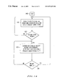
- FIG. 2 The method of the present invention is shown in FIG. 2 where the process starts at block 205 .
- a desired signal search is performed in block 210 where a frequency domain method performs narrow-band interference rejection.
- Decision block 215 determines whether or not a desired signal has been detected (synchronization has occurred), and returns to block 210 if no signal is present.
- the process proceeds to block 220 where matched filter coefficients are computed that both 1) despread the desired spread spectrum signal and 2) reject narrowband jammers (interference) by including a notch in the filter frequency response for each jammer.
- the method then proceeds to the time domain where blocks 225 and 230 despread and demodulate the received message using matched filters calculated in block 220 .
- the demodulation process continues until the message is complete.
- search mode resumes at block 210 using the frequency domain method.
- the matched filter computations of block 225 are less than one-sixth of the computations of the FFT alone of block 210 .
- This method thus minimizes overall computation compared to prior art.
- the prior art computes an FFT and an inverse FFT for each demodulated message bit.
- the narrowband interference remains stationary over the message duration for this technique to be maximally effective. This technique detects narrowband (NB) interference only once, at the beginning of a message.
- NB narrowband
- a digitally sampled signal record 302 of M spreading code periods is multiplied 304 by a data taper window 306 , also of M spreading code periods.
- the data taper window suppresses spectral leakage of narrow-band interference. (See Gumas as cited above.)
- the signal record 302 is sampled at K samples per code chip.
- the output of multiplier 304 is converted into the frequency domain by a Fast Fourier Transform (FT) 308 .
- FT Fast Fourier Transform
- the prime factor FFT is used as disclosed in the above cross-referenced U.S. patent application Ser. No. 08/929,891.
- the frequency of any narrowband jammers is determined and they are excised (magnitude set to zero) in block 314 .
- the frequencies of the excised spectral lines (if any) are recorded in block 316 .
- a time-frequency correlation process 320 is performed, followed by a synchronization (desired signal present) process 322 .
- the result of the synchronization process is a code delay ⁇ 326 and a frequency error ⁇ 328 (transmitter-receiver frequency difference, i.e., a frequency channel).
- Steps 308 , 320 , and 322 are disclosed in patent application Ser. No. 08/929,891 as cited above.
- the method 314 for interference rejection is further explained in FIG. 4 where the process begins in block 405 .
- An initial signal power in all frequency bins is computed in block 410 prior to block 415 where the spectral line with the largest magnitude is selected.
- Block 420 then computes a second signal power in all frequency bins with the selected line removed from the power computation.
- the process proceeds to decision block 425 which computes the difference between the two power calculations. If the difference is less than a predetermined amount delta between the two power calculations, then it is determined that the removed spectral line (from step 415 ) is from a desired spread spectrum signal, and the process exits through block 430 . In the preferred embodiment of the present invention, this delta value is equal to 0.4 dB.
- a system with a different configuration requires a different value for delta.
- the difference between the two power calculations is greater than the predetermined delta value, then it is determined that the removed spectral line is from a narrowband jammer. This is due to the fact that a NB jammer will appear with its energy concentrated in one or a few spectral lines. In contrast, the desired signal will appear with its energy divided among all spectral lines.
- the spectral line is excised (magnitude set to zero) in block 435 , and then block 440 enters this spectral line into a list of spectral lines that are to be removed by subsequent operations.
- Block 445 re-labels the power calculation from block 420 as the initial signal power value, and then returns process flow to block 415 . This process continues until the condition in block 425 is satisfied and spectral lines from narrow band jammers are excised and listed. These excised lines are recorded in step 316 of FIG. 3 . This is the preferred embodiment of block 314 .
- the prior art discloses setting the magnitude of all spectral lines to one thereby retaining only the phase information of the received signal. This suppresses a narrowband interference with a frequency domain limiter.
- a modified approach discards the magnitude information and replaces it with a normalized magnitude of the desired signal.
- the method 314 of FIG. 3 which is the preferred embodiment of the present invention, produces a higher desired signal to jammer ratio than prior art methods by discarding all of the jammer energy.
- the steps in FIG. 3 represent the minimum number of steps in a narrow-band interference rejecting synchronizer of the present invention. Additional steps are available to decrease computational loading of the DSP device. The first of these steps is shown in block 510 of FIG. 5 .
- This downsampling step reduces the computational load on the DSP by a factor of M, the number of code periods in the data record. M is equal to 3 in the preferred embodiment of the present invention.
- the data taper window is a member of the three frequency term window family of which the Blackman window is an example.
- M can take on the value of one, two, or more.
- a message preamble of constant symbols for receiver synchronization followed by message information symbols is transmitted in the preferred embodiment of the present invention.
- This downsampling step does not degrade the desired signal energy of the message preamble because the signal energy of constant symbols is zero in the cast off samples.
- a band-limiting step 612 is shown in FIG. 6 that retains only the center 1/K data points of the desired signal frequency spectrum. This reduces the computational load on the DSP device by a factor of K. K is equal to 4 in the preferred embodiment of the present invention. One skilled in the art recognizes that K can take on the value of one, two, or more. This band-limiting step does not degrade the desired signal energy if the corresponding transmitter is similarly band-limited.
- the preferred embodiment of the present invention is shown in FIG. 7 . It contains all of the aforementioned techniques to reduce computational loading.
- the preferred embodiment includes the downsampler 710 and the band-limiting block 712 to reduce the computational loading from (M*K*L) to L.
- L is the number of chips in the spreading code, which represents the minimum number of data points necessary to calculate a full process gain code delay correlation in a spread spectrum receiver.
- the order of blocks 710 and 712 is interchangeable.
- FIGS. 3 through 7 One result of the methods in FIGS. 3 through 7 is to determine signal detection (desired signal present) and a synchronization condition.
- an additional result of the process from FIGS. 3 through 7 is a list of spectral lines that were the result of narrowband jammers (interference). This list, which is stored in memory, is used to generate a set of I/Q matched filter coefficients that will jointly 1) reject the detected narrowband interference, 2) despread the received spread spectrum signal, and alternately 3) downconvert the signal from a near-baseband signal to baseband, 4) band limit the signal, and 5) channelize (remove the transmitter/receiver frequency error) the signal.
- the method 220 for generating the I/Q matched filter coefficients is explained in FIG. 8 .
- M periods of the spreading code digitized at K samples per chip 832 are converted into the frequency domain by FFT block 838 .
- Block 840 performs a complex conjugate operation on the output of block 838 .
- the frequency error ⁇ 328 is used by the frequency shift block 818 to frequency shift the output of complex conjugate block 840 .
- This is a data indexing process and does not add computational complexity to the signal processing method. In the most elementary receivers frequency error removal is not performed.
- the spectral lines from block 816 are excised by setting the magnitude to zero in block 814 .
- the interference rejection block 814 uses the list of spectral lines from block 816 .
- the list of interfering lines 816 corresponds to block 316 of FIG. 3 .
- Inverse FFT block 848 converts this data set into the time domain.
- the complex output inverse FFT produces I (real part) and Q (complex part) sequences.
- the resulting signal is combined with data taper window 806 (similar to the data taper window 306 from FIG. 3 ) in multiplier 850 .
- the result is the set of I/Q filter coefficients 852 . These coefficients are uniquely generated each time the receiver locks onto a desired spread spectrum signal. Step 838 is disclosed in patent application Ser. No. 08/929,891 above cross-referenced.
- FIG. 8 represents the minimum number of steps required to calculate the matched filter I/Q coefficients. Additional steps may be added to increase the computational efficiency of the DSP device.
- FIG. 9 requires only one period of the spreading code 932 , but adds the up-sampling step 946 to replicate M code periods in the matched filter coefficients. (The upsampling by a factor of M adds M-1 zeroes between the existing data points.)
- the list of interfering lines 916 corresponds to block 516 of FIG. 5 .
- FIG. 10 requires M periods of the spreading code 1032 .
- the band-limiting step 1042 and zero pad step 1044 are added to reduce the computational loading of the center part of the method.
- the zero pad function block 1044 appends [(K ⁇ 1)*L] zero values beyond the Nyquist frequency of the data points from 1014 to bring the number of data points up to (M*K*L). This produces an ideal band-limited reference code at K samples per code chip.
- the list of interfering lines 1016 corresponds to block 616 of FIG. 6 .
- FIG. 11 The preferred embodiment of the present invention is depicted in FIG. 11 .
- This Figure shows one period of the spreading code in block 1132 , a band-limiting step 1142 , a zero pad step 1144 , and an up-sampling step 1146 . This provides highest computational efficiency.
- the list of interfering lines 1116 corresponds to block 716 of FIG. 7 .
- the order of blocks 1144 and 1146 is interchangeable.
- Block 1202 shows a signal record of M code periods in length. This signal record is obtained similarly to block 302 from FIG. 3 . It is sampled at delay ⁇ 326 as determined by the synchronization method to align the transmitter and receiver codes in time.
- the in-phase and quadrature (I and Q) portions of the message signal are extracted by matched filter 1254 .
- the matched filter coefficients are the output 852 , 952 , 1052 or 1152 of FIG. 8 , 9 , 10 or 11 respectively.
- the frequency response of the matched filter includes a notch for each jammer.
- the output of block 1254 contains information from M code periods of the message.
- IIR filter 1262 removes the inter-symbol interference (symbol-smearing effect) and extracts the present message symbol I and Q values for demodulator block 1264 .
- FIG. 13 An alternative to the method of FIG. 2 is shown in FIG. 13 .
- the method of FIG. 2 maintains the same set of matched coefficients throughout the lifetime of the message.
- narrowband jammers can appear and disappear more often. This may be due to pulsed narrowband transmitters or a slow frequency hopping transmitter residing in the same frequency band as the spread spectrum receiver.
- steps 1335 and 1340 are added to the method of FIG. 2 .
- Block 1335 performs a frequency domain search for narrowband jammers.
- the method of block 1335 is explained by the block diagram of FIG. 3 . Note that since the receiver has already achieved a synchronization condition, blocks 320 and 322 are not executed as part of block 1335 .
- the list of interfering spectral lines 316 is the only output of interest from the execution of block 1335 . This list is used to update the matched filter coefficients. Depending on the configuration of the receiver, block 1335 may operate in parallel with the demodulation block 1325 . Decision block 1340 tests whether or not the jammer rejection list has been completed. If a new jammer rejection list has been completed, then the process proceeds to block 1320 ; otherwise, the process proceeds to block 1325 .
- Block 1335 has corresponding explanations in the block diagrams of FIGS. 5 , 6 , and 7 .
- the method of FIG. 14 may be required in highly dynamic environments. If it is necessary to update the interfering spectral line list every message symbol, the most computationally efficient approach is depicted in FIG. 14 where the entire process takes place in the frequency domain.
- the process starts in block 1405 and then proceeds to block 1410 where a frequency domain method as disclosed above ( 210 ) performs signal acquisition with narrow-band interference rejection.
- Decision block 1415 determines whether or not a desired signal has been detected, and returns to block 1410 if no signal is present. Once a desired signal has been detected, the process proceeds to block 1425 where a frequency domain method is executed that both 1 ) despreads the desired spread spectrum signal and 2) rejects narrowband jammers (interference) by excising the jammer spectral lines.
- Block 1425 then demodulates the message symbol. If the message is not complete, decision block 1430 proceeds to block 1425 to 1 ) identify and excise narrowband jammers, 2) matched filter despread, and 3) demodulate another message symbol. If the message is complete, block 1430 proceeds to block 1410 to resume search mode.
- the method 1425 of FIG. 14 is explained in FIG. 15 .
- M periods of the spreading code are applied to FFT 1538 and then to complex conjugate block 1540 , to produce the reference code signal 1556 .
- This reference code can be pre-computed and stored in memory to alleviate the real-time computing resources of the DSP device.
- the input signal record of M code periods 1502 is multiplied 1504 by a data taper window of length M code periods 1506 .
- the result is converted into the frequency domain by FFT 1508 and then the narrowband jammers are removed in block 1514 similarly to block 314 of FIG. 3 .
- Block 1518 performs a frequency shift.
- the reference code 1556 consisting of M periods of code, is multiplied 1558 by the M periods of interference excised data (output of block 1518 ). This signal is then summed in 1560 producing the I (in-phase) and Q (quadrature) message symbol components.
- block 1560 is replaced by an inverse FFT.
- One output point of the prior art inverse FFT is the despread desired signal. By sampling the received signal at delay ⁇ as in block 1502 , the despread signal appears in the center output point of the prior art inverse FFT.
- the center point of an inverse FFT is the average of the input points.
- a summation of the input points is shown in block 1560 (a summation is a scaled average). This replaces the prior art inverse FFT with a simpler computation.
- the output of block 1560 contains information from M code periods of the message.
- IIR filter 1562 removes the inter-symbol interference (symbol-smearing effect) and extracts the present message symbol I and Q values for demodulator block 1564 .
- the steps in FIG. 15 represent the minimum number of steps in a frequency domain narrow-band interference rejecting despreader of the present invention. Additional steps are available to decrease computational loading of the DSP device. The first of these steps is shown in block 1610 of FIG. 16 .
- This downsampling step reduces the computational load on the DSP by a factor of M, the number of code periods in the data record. M is equal to 3 in the preferred embodiment of the present invention.
- M can take on the value of one, two, or more. This also allows one period of code 1632 to be input into the process instead of the M periods of code 1532 from FIG. 15 .
- band-limiting steps 1742 and 1712 are shown in FIG. 17 that retain only the center 1/K data points from both the code reference thread (blocks 1732 , 1738 , 1740 , 1742 , and 1756 ) and the desired signal input thread (blocks 1702 , 1704 , 1706 , 1708 , 1712 , and 1718 ) in the frequency spectrum.
- K is equal to 4 in the preferred embodiment of the present invention.
- K can take on the value of one, two, or more. This band-limiting step does not degrade the desired signal energy if the corresponding transmitter is similarly band-limited.
- FIG. 18 shows one period of the spreading code in block 1832 , downsampling step 1810 , and band-limiting steps 1842 and 1812 . This provides highest efficiency by reducing the computational loading from (M*K*L) to L.
- L is the number of chips in the spreading code, which represents the minimum number of data points required by a spread spectrum receiver to demodulate a message symbol with full process gain.
- the order of blocks 1810 and 1812 is interchangeable.
- the invention may also be implemented by the preparation of application specific integrated circuits or by interconnecting an appropriate network of conventional component circuits, as will be readily apparent to those skilled in the art.
- the present invention includes a computer program product which is a storage medium including instructions which can be used to program a computer to perform processes of the invention.
- the storage medium can include, but is not limited to, any type of disk including floppy disks, optical discs, CD-ROMs, and magneto-optical disks, ROMs, RAMs, EPROMs, EEPROMs, magnetic or optical cards, or any type of media, including hard drives, suitable for storing electronic instructions.
Landscapes
- Engineering & Computer Science (AREA)
- Computer Networks & Wireless Communication (AREA)
- Signal Processing (AREA)
- Radar, Positioning & Navigation (AREA)
- Remote Sensing (AREA)
- Noise Elimination (AREA)
Abstract
Description
Claims (29)
Priority Applications (1)
| Application Number | Priority Date | Filing Date | Title |
|---|---|---|---|
| US09/720,270 US6975673B1 (en) | 1998-07-14 | 1999-07-14 | Narrow-band interference rejecting spread spectrum radio system and method |
Applications Claiming Priority (3)
| Application Number | Priority Date | Filing Date | Title |
|---|---|---|---|
| US9283998P | 1998-07-14 | 1998-07-14 | |
| US09/720,270 US6975673B1 (en) | 1998-07-14 | 1999-07-14 | Narrow-band interference rejecting spread spectrum radio system and method |
| PCT/US1999/014146 WO2000004657A1 (en) | 1998-07-14 | 1999-07-14 | Narrow-band interference rejecting spread spectrum radio system and method |
Publications (1)
| Publication Number | Publication Date |
|---|---|
| US6975673B1 true US6975673B1 (en) | 2005-12-13 |
Family
ID=35452637
Family Applications (1)
| Application Number | Title | Priority Date | Filing Date |
|---|---|---|---|
| US09/720,270 Expired - Lifetime US6975673B1 (en) | 1998-07-14 | 1999-07-14 | Narrow-band interference rejecting spread spectrum radio system and method |
Country Status (1)
| Country | Link |
|---|---|
| US (1) | US6975673B1 (en) |
Cited By (52)
| Publication number | Priority date | Publication date | Assignee | Title |
|---|---|---|---|---|
| US20030021367A1 (en) * | 2001-05-15 | 2003-01-30 | Smith Francis J. | Radio receiver |
| US20040218576A1 (en) * | 2001-07-27 | 2004-11-04 | Yasumi Imagawa | Receiver and communication terminal |
| US20050047487A1 (en) * | 2003-09-01 | 2005-03-03 | Gcomm Corporation | Spread spectrum communication system receiving device |
| US20060029142A1 (en) * | 2004-07-15 | 2006-02-09 | Oren Arad | Simplified narrowband excision |
| US20060176965A1 (en) * | 2005-02-07 | 2006-08-10 | Harris Corporation | System and method for removing interfering narrowband signals from wide bandwidth receive signal |
| US20070082633A1 (en) * | 2005-10-06 | 2007-04-12 | Staccato Communications, Inc. | Avoidance of wireless devices |
| US20070080800A1 (en) * | 2005-10-06 | 2007-04-12 | Staccato Communications, Inc. | Creation of environments to detect wireless devices |
| US20070147410A1 (en) * | 2005-11-29 | 2007-06-28 | Staccato Communications, Inc. | Detecting wireless devices to inform about a quiet period |
| US20070165586A1 (en) * | 2005-11-29 | 2007-07-19 | Staccato Communications, Inc. | Quiet periods for detecting wireless devices |
| US7277475B1 (en) * | 2003-09-26 | 2007-10-02 | United States Of America As Represented By The Secretary Of The Navy | Narrowband interference excision device |
| US20080019420A1 (en) * | 2006-03-21 | 2008-01-24 | Staccato Communications, Inc. | Exchange of detection and avoidance information |
| US20080069184A1 (en) * | 2001-10-19 | 2008-03-20 | Shinichiro Ohmi | System and method for spread spectrum communication |
| US7366243B1 (en) * | 2003-10-29 | 2008-04-29 | Itt Manufacturing Enterprises, Inc. | Methods and apparatus for transmitting non-contiguous spread spectrum signals for communications and navigation |
| US20080268779A1 (en) * | 2007-03-29 | 2008-10-30 | Staccato Communications, Inc. | DAA concept with uplink detection: frequency domain quiet periods |
| US20090010366A1 (en) * | 2005-03-01 | 2009-01-08 | Huawei Technologies Co., Ltd. | Method and device for suppressing narrowband interference |
| US20090028223A1 (en) * | 2007-07-27 | 2009-01-29 | Mediatek Inc. | Signal receiver and method for estimating residual doppler frequencies of signals thereof |
| US7518524B1 (en) | 2005-10-06 | 2009-04-14 | Staccato Communications, Inc. | Announcements to facilitate detection of wireless devices |
| US20090096668A1 (en) * | 2007-10-11 | 2009-04-16 | Mediatek Inc. | Signal acquisition/tracking method and correlator for the same |
| US20100195775A1 (en) * | 2009-02-03 | 2010-08-05 | Harris Corporation | Communications device including a filter for notching wideband receive signals and associated methods |
| US20100302087A1 (en) * | 2009-05-28 | 2010-12-02 | Lockheed Martin Corporation | Smart Signal Jammer |
| US20100304681A1 (en) * | 2009-06-01 | 2010-12-02 | Ghassemzadeh Saeed S | Narrowband interference rejection for ultra-wideband systems |
| US20110105037A1 (en) * | 2009-10-30 | 2011-05-05 | Qualcomm Incorporated | Methods and systems for interference cancellation in multi-mode coexistence modems |
| US20110103431A1 (en) * | 2009-10-30 | 2011-05-05 | Qualcomm Incorporated | Methods and systems for interference cancellation in multi-mode coexistence modems |
| EP2408117A1 (en) * | 2010-07-13 | 2012-01-18 | ST-Ericsson SA | Synchronizing and detecting interference in wireless receiver |
| US20120295565A1 (en) * | 2011-05-16 | 2012-11-22 | Raytheon Company | System and method for analog interference suppression in pulsed signal processing |
| US8614940B1 (en) * | 2012-11-14 | 2013-12-24 | The Aerospace Corporation | Systems and methods for reducing narrow bandwidth interference contained in broad bandwidth signals |
| US20140256342A1 (en) * | 2008-11-11 | 2014-09-11 | Isco International, Llc | Method and apparatus for an adaptive filter architecture |
| US20150222322A1 (en) * | 2014-01-31 | 2015-08-06 | Harris Corporation | Communication system with narrowband interference mitigation and related methods |
| US9118401B1 (en) * | 2014-10-28 | 2015-08-25 | Harris Corporation | Method of adaptive interference mitigation in wide band spectrum |
| US9198055B2 (en) | 1999-02-02 | 2015-11-24 | Isco International, Llc | Method and device for maintaining the performance quality of a communication system in the presence of narrow band interference |
| US9276797B2 (en) | 2014-04-16 | 2016-03-01 | Digi International Inc. | Low complexity narrowband interference suppression |
| US9313680B2 (en) | 2013-03-15 | 2016-04-12 | Isco International, Llc | Method and apparatus for signal interference processing |
| US9628122B1 (en) * | 2016-07-25 | 2017-04-18 | The Aerospace Corporation | Circuits and methods for reducing interference that spectrally overlaps a desired signal based on dynamic gain control and/or equalization |
| US9647719B2 (en) * | 2015-02-16 | 2017-05-09 | Federated Wireless, Inc. | Method, system, and apparatus for spectrum sensing of radar signals |
| US9743293B1 (en) | 2016-07-25 | 2017-08-22 | Samsung Electronics Co., Ltd. | System and method for local spreading code manipulation for interference mitigation |
| US9775116B2 (en) | 2014-05-05 | 2017-09-26 | Isco International, Llc | Method and apparatus for increasing performance of communication links of cooperative communication nodes |
| US9912503B2 (en) * | 2015-12-30 | 2018-03-06 | Abov Semiconductor Co., Ltd. | Bluetooth signal receiving method and device using improved carrier frequency offset compensation |
| US10056675B1 (en) | 2017-08-10 | 2018-08-21 | The Aerospace Corporation | Systems and methods for reducing directional interference based on adaptive excision and beam repositioning |
| US10652835B2 (en) | 2016-06-01 | 2020-05-12 | Isco International, Llc | Signal conditioning to mitigate interference impacting wireless communication links in radio access networks |
| US10687284B2 (en) | 2014-05-05 | 2020-06-16 | Isco International, Llc | Method and apparatus for increasing performance of communication paths for communication nodes |
| US10833783B2 (en) | 2017-08-09 | 2020-11-10 | Isco International, Llc | Method and apparatus for monitoring, detecting, testing, diagnosing and/or mitigating interference in a communication system |
| US20200371247A1 (en) * | 2017-12-20 | 2020-11-26 | Centre National D'etudes Spatiales | Receiver-independent spoofing detection device |
| US10879945B2 (en) | 2017-04-05 | 2020-12-29 | Isco International, Llc | Methods, systems and devices to improve channel utilization |
| US11101843B1 (en) * | 2020-02-28 | 2021-08-24 | Amazon Technologies, Inc. | Selective narrowband interference cancellation |
| US11212015B2 (en) | 2020-05-19 | 2021-12-28 | The Aerospace Corporation | Interference suppression using machine learning |
| CN114200486A (en) * | 2021-12-24 | 2022-03-18 | 中电科星河北斗技术(西安)有限公司 | Transform domain filtering narrow-band interference suppression method and device |
| US11362693B2 (en) | 2017-08-09 | 2022-06-14 | Isco International, Llc | Method and apparatus for detecting and analyzing passive intermodulation interference in a communication system |
| CN114915316A (en) * | 2022-03-31 | 2022-08-16 | 中国人民解放军战略支援部队航天工程大学 | Band-limited direct sequence spread spectrum signal digital code tracking method based on frequency domain processing |
| WO2023249842A1 (en) * | 2022-06-24 | 2023-12-28 | Atc Technologies, Llc | Intelligent packet repetition in mobile satellite service (mss) links to overcome channel blockages |
| CN117792432A (en) * | 2023-12-29 | 2024-03-29 | 电子科技大学 | A synchronization acquisition method based on frequency hopping pulse merging |
| CN119030567A (en) * | 2024-07-18 | 2024-11-26 | 中国电子科技集团公司第五十四研究所 | A receiving device for resisting narrowband interference in direct sequence spread spectrum communication system |
| US12255698B2 (en) | 2020-03-25 | 2025-03-18 | Atc Technologies, Llc | Intelligent packet repetition in mobile satellite service (MSS) links to overcome channel blockages |
Citations (8)
| Publication number | Priority date | Publication date | Assignee | Title |
|---|---|---|---|---|
| US4613978A (en) | 1984-06-14 | 1986-09-23 | Sperry Corporation | Narrowband interference suppression system |
| US5271038A (en) * | 1990-09-10 | 1993-12-14 | Hughes Aircraft Company | Distortion suppression using thresholding techniques |
| US5377223A (en) | 1993-08-30 | 1994-12-27 | Interdigital Technology Corporation | Notch filtering a spread spectrum signal using fourier series coefficients |
| US5612978A (en) | 1995-05-30 | 1997-03-18 | Motorola, Inc. | Method and apparatus for real-time adaptive interference cancellation in dynamic environments |
| US5640416A (en) | 1995-06-07 | 1997-06-17 | Comsat Corporation | Digital downconverter/despreader for direct sequence spread spectrum communications system |
| US5671247A (en) | 1995-10-24 | 1997-09-23 | Motorola, Inc. | Method and apparatus for interference suppression in spread spectrum signals |
| US5852630A (en) * | 1997-07-17 | 1998-12-22 | Globespan Semiconductor, Inc. | Method and apparatus for a RADSL transceiver warm start activation procedure with precoding |
| US5999561A (en) * | 1997-05-20 | 1999-12-07 | Sanconix, Inc. | Direct sequence spread spectrum method, computer-based product, apparatus and system tolerant to frequency reference offset |
-
1999
- 1999-07-14 US US09/720,270 patent/US6975673B1/en not_active Expired - Lifetime
Patent Citations (8)
| Publication number | Priority date | Publication date | Assignee | Title |
|---|---|---|---|---|
| US4613978A (en) | 1984-06-14 | 1986-09-23 | Sperry Corporation | Narrowband interference suppression system |
| US5271038A (en) * | 1990-09-10 | 1993-12-14 | Hughes Aircraft Company | Distortion suppression using thresholding techniques |
| US5377223A (en) | 1993-08-30 | 1994-12-27 | Interdigital Technology Corporation | Notch filtering a spread spectrum signal using fourier series coefficients |
| US5612978A (en) | 1995-05-30 | 1997-03-18 | Motorola, Inc. | Method and apparatus for real-time adaptive interference cancellation in dynamic environments |
| US5640416A (en) | 1995-06-07 | 1997-06-17 | Comsat Corporation | Digital downconverter/despreader for direct sequence spread spectrum communications system |
| US5671247A (en) | 1995-10-24 | 1997-09-23 | Motorola, Inc. | Method and apparatus for interference suppression in spread spectrum signals |
| US5999561A (en) * | 1997-05-20 | 1999-12-07 | Sanconix, Inc. | Direct sequence spread spectrum method, computer-based product, apparatus and system tolerant to frequency reference offset |
| US5852630A (en) * | 1997-07-17 | 1998-12-22 | Globespan Semiconductor, Inc. | Method and apparatus for a RADSL transceiver warm start activation procedure with precoding |
Non-Patent Citations (2)
| Title |
|---|
| Kohri, T. (Spread Spectrum Techniques and Applications, 994. IEEE ISSSTA '94, IEEE Third International Symposium on, Jul. 4-6, 1994 pp.: 521-525 vol.2). * |
| Laster et al. (Interference Rejection in Digital wireless communications, IEEE signal processing magazine, May 1997). * |
Cited By (179)
| Publication number | Priority date | Publication date | Assignee | Title |
|---|---|---|---|---|
| US9247553B2 (en) | 1999-02-02 | 2016-01-26 | Isco International, Llc | Method and device for maintaining the performance quality of a communication system in the presence of narrow band interference |
| US9232423B2 (en) | 1999-02-02 | 2016-01-05 | Isco International, Llc | Method and device for maintaining the performance quality of a communication system in the presence of narrow band interference |
| US9894662B2 (en) | 1999-02-02 | 2018-02-13 | Isco International, Llc | Method and device for maintaining the performance quality of a communication system in the presence of narrow band interference |
| US9788331B2 (en) | 1999-02-02 | 2017-10-10 | Isco International, Llc | Method and device for maintaining the performance quality of a communication system in the presence of narrow band interference |
| US10039117B2 (en) | 1999-02-02 | 2018-07-31 | Isco International, Llc | Method and device for maintaining the performance quality of a communication system in the presence of narrow band interference |
| US9198055B2 (en) | 1999-02-02 | 2015-11-24 | Isco International, Llc | Method and device for maintaining the performance quality of a communication system in the presence of narrow band interference |
| US9215723B2 (en) | 1999-02-02 | 2015-12-15 | Isco International, Llc | Method and device for maintaining the performance quality of a communication system in the presence of narrow band interference |
| US9706559B2 (en) | 1999-02-02 | 2017-07-11 | Isco International, Llc | Method and device for maintaining the performance quality of a communication system in the presence of narrow band interference |
| US9215719B2 (en) | 1999-02-02 | 2015-12-15 | Isco International, Llc | Method and device for maintaining the performance quality of a communication system in the presence of narrow band interference |
| US9451495B2 (en) | 1999-02-02 | 2016-09-20 | Isco International, Llc | Method and device for maintaining the performance quality of a communication system in the presence of narrow band interference |
| US7346134B2 (en) * | 2001-05-15 | 2008-03-18 | Finesse Wireless, Inc. | Radio receiver |
| US20030021367A1 (en) * | 2001-05-15 | 2003-01-30 | Smith Francis J. | Radio receiver |
| US20040218576A1 (en) * | 2001-07-27 | 2004-11-04 | Yasumi Imagawa | Receiver and communication terminal |
| US8325780B2 (en) * | 2001-10-19 | 2012-12-04 | Panasonic Corporation | System and method for spread spectrum communication |
| US20080069184A1 (en) * | 2001-10-19 | 2008-03-20 | Shinichiro Ohmi | System and method for spread spectrum communication |
| US20050047487A1 (en) * | 2003-09-01 | 2005-03-03 | Gcomm Corporation | Spread spectrum communication system receiving device |
| US7277475B1 (en) * | 2003-09-26 | 2007-10-02 | United States Of America As Represented By The Secretary Of The Navy | Narrowband interference excision device |
| US7366243B1 (en) * | 2003-10-29 | 2008-04-29 | Itt Manufacturing Enterprises, Inc. | Methods and apparatus for transmitting non-contiguous spread spectrum signals for communications and navigation |
| US7573947B2 (en) * | 2004-07-15 | 2009-08-11 | Terayon Communication Systems, Inc. | Simplified narrowband excision |
| US20060029142A1 (en) * | 2004-07-15 | 2006-02-09 | Oren Arad | Simplified narrowband excision |
| US20080069258A1 (en) * | 2004-07-15 | 2008-03-20 | Oren Arad | Simplified narrowband excision |
| US20060176965A1 (en) * | 2005-02-07 | 2006-08-10 | Harris Corporation | System and method for removing interfering narrowband signals from wide bandwidth receive signal |
| US7512197B2 (en) * | 2005-02-07 | 2009-03-31 | Harris Corporation | System and method for removing interfering narrowband signals from wide bandwidth receive signal |
| US20090010366A1 (en) * | 2005-03-01 | 2009-01-08 | Huawei Technologies Co., Ltd. | Method and device for suppressing narrowband interference |
| US7957495B2 (en) * | 2005-03-01 | 2011-06-07 | Huawei Technologies Co., Ltd. | Method and device for suppressing narrowband interference |
| US7589627B2 (en) | 2005-10-06 | 2009-09-15 | Staccato Communications, Inc. | Creation of environments to detect wireless devices |
| US7518524B1 (en) | 2005-10-06 | 2009-04-14 | Staccato Communications, Inc. | Announcements to facilitate detection of wireless devices |
| US20070080800A1 (en) * | 2005-10-06 | 2007-04-12 | Staccato Communications, Inc. | Creation of environments to detect wireless devices |
| US20070082633A1 (en) * | 2005-10-06 | 2007-04-12 | Staccato Communications, Inc. | Avoidance of wireless devices |
| US20070165586A1 (en) * | 2005-11-29 | 2007-07-19 | Staccato Communications, Inc. | Quiet periods for detecting wireless devices |
| US20070147410A1 (en) * | 2005-11-29 | 2007-06-28 | Staccato Communications, Inc. | Detecting wireless devices to inform about a quiet period |
| US20080019420A1 (en) * | 2006-03-21 | 2008-01-24 | Staccato Communications, Inc. | Exchange of detection and avoidance information |
| US20080268779A1 (en) * | 2007-03-29 | 2008-10-30 | Staccato Communications, Inc. | DAA concept with uplink detection: frequency domain quiet periods |
| US20110142170A1 (en) * | 2007-07-27 | 2011-06-16 | Mediatek Inc. | Signal Receiver and Method for Estimating Residual Doppler Frequencies of Signals Thereof |
| US20090028223A1 (en) * | 2007-07-27 | 2009-01-29 | Mediatek Inc. | Signal receiver and method for estimating residual doppler frequencies of signals thereof |
| US8149937B2 (en) | 2007-07-27 | 2012-04-03 | Mediatek Inc. | Signal receiver and method for estimating residual doppler frequencies of signals thereof |
| US7899126B2 (en) | 2007-07-27 | 2011-03-01 | Mediatek Inc. | Signal receiver and method for estimating residual doppler frequencies of signals thereof |
| US7916078B2 (en) | 2007-10-11 | 2011-03-29 | Mediatek Inc. | Signal acquisition/tracking method and correlator for the same |
| US20090096668A1 (en) * | 2007-10-11 | 2009-04-16 | Mediatek Inc. | Signal acquisition/tracking method and correlator for the same |
| US7800536B2 (en) | 2007-10-11 | 2010-09-21 | Mediatek, Inc. | Signal acquisition/tracking method and correlator for the same |
| US20100309960A1 (en) * | 2007-10-11 | 2010-12-09 | Kun-Tso Chen | Signal acquisition/tracking method and correlator for the same |
| US10461802B2 (en) | 2008-11-11 | 2019-10-29 | Isco International, Llc | Method and apparatus for an adaptive filter architecture |
| US9647720B2 (en) | 2008-11-11 | 2017-05-09 | Isco International, Llc | Method and apparatus for an adaptive filter architecture |
| US9654170B2 (en) | 2008-11-11 | 2017-05-16 | Isco International, Llc | Method and apparatus for an adaptive filter architecture |
| US20140256342A1 (en) * | 2008-11-11 | 2014-09-11 | Isco International, Llc | Method and apparatus for an adaptive filter architecture |
| US10097235B2 (en) | 2008-11-11 | 2018-10-09 | Isco International, Llc | Method and apparatus for an adaptive filter architecture |
| US9294144B2 (en) | 2008-11-11 | 2016-03-22 | Isco International, Llc | Method and apparatus for an adaptive filter architecture |
| US9281864B2 (en) * | 2008-11-11 | 2016-03-08 | Isco International, Llc | Method and apparatus for an adaptive filter architecture |
| US9231650B2 (en) | 2008-11-11 | 2016-01-05 | Isco International, Llc | Method and apparatus for an adaptive filter architecture |
| US8098782B2 (en) * | 2009-02-03 | 2012-01-17 | Harris Corporation | Communications device including a filter for notching wideband receive signals and associated methods |
| US20100195775A1 (en) * | 2009-02-03 | 2010-08-05 | Harris Corporation | Communications device including a filter for notching wideband receive signals and associated methods |
| US20100302087A1 (en) * | 2009-05-28 | 2010-12-02 | Lockheed Martin Corporation | Smart Signal Jammer |
| US7982654B2 (en) | 2009-05-28 | 2011-07-19 | Lockheed Martin Corporation | Smart signal jammer |
| US8406278B2 (en) * | 2009-06-01 | 2013-03-26 | At&T Intellectual Property I, L.P. | Narrowband interference rejection for ultra-wideband systems |
| US20100304681A1 (en) * | 2009-06-01 | 2010-12-02 | Ghassemzadeh Saeed S | Narrowband interference rejection for ultra-wideband systems |
| US8687672B2 (en) | 2009-06-01 | 2014-04-01 | At&T Intellectual Property I, L.P. | Narrowband interference rejection for ultra-wideband systems |
| US8576965B2 (en) * | 2009-10-30 | 2013-11-05 | Qualcomm Incorporated | Methods and systems for interference cancellation in multi-mode coexistence modems |
| US20110105037A1 (en) * | 2009-10-30 | 2011-05-05 | Qualcomm Incorporated | Methods and systems for interference cancellation in multi-mode coexistence modems |
| US20110103431A1 (en) * | 2009-10-30 | 2011-05-05 | Qualcomm Incorporated | Methods and systems for interference cancellation in multi-mode coexistence modems |
| US9100084B2 (en) | 2010-07-13 | 2015-08-04 | St-Ericsson Sa | Synchronizing and detecting interference in wireless receiver |
| WO2012007278A1 (en) * | 2010-07-13 | 2012-01-19 | St-Ericsson Sa | Synchronizing and detecting interference in wireless receiver |
| EP2408117A1 (en) * | 2010-07-13 | 2012-01-18 | ST-Ericsson SA | Synchronizing and detecting interference in wireless receiver |
| US20120295565A1 (en) * | 2011-05-16 | 2012-11-22 | Raytheon Company | System and method for analog interference suppression in pulsed signal processing |
| US9065521B1 (en) | 2012-11-14 | 2015-06-23 | The Aerospace Corporation | Systems and methods for reducing narrow bandwidth and directional interference contained in broad bandwidth signals |
| US8614940B1 (en) * | 2012-11-14 | 2013-12-24 | The Aerospace Corporation | Systems and methods for reducing narrow bandwidth interference contained in broad bandwidth signals |
| US10079667B2 (en) | 2013-03-15 | 2018-09-18 | Isco International, Llc | Method and apparatus for signal interference processing |
| US11950270B2 (en) | 2013-03-15 | 2024-04-02 | Isco International, Llc | Method and apparatus for collecting and processing interference information |
| US9634819B2 (en) | 2013-03-15 | 2017-04-25 | Isco International, Llc | Method and apparatus for signal interference processing |
| US9729196B2 (en) | 2013-03-15 | 2017-08-08 | Isco International, Llc | Method and apparatus for avoiding interference |
| US9729301B2 (en) | 2013-03-15 | 2017-08-08 | Isco International, Llc | Method and apparatus for mitigating signal interference in a feedback system |
| US9742547B2 (en) | 2013-03-15 | 2017-08-22 | Isco International, Llc | Method and apparatus for signal interference processing |
| US11445517B2 (en) | 2013-03-15 | 2022-09-13 | Isco International, Llc | Method and apparatus for signal interference processing |
| US11375516B2 (en) | 2013-03-15 | 2022-06-28 | Isco International, Llc | Method and apparatus for signal interference avoidance |
| US11582763B2 (en) | 2013-03-15 | 2023-02-14 | Isco International, Llc | Creating library of interferers |
| US11304204B2 (en) | 2013-03-15 | 2022-04-12 | Isco International, Llc | Method and apparatus for signal interference processing |
| US9832000B2 (en) | 2013-03-15 | 2017-11-28 | Isco International, Llc | Method and apparatus for signal interference processing |
| US10667275B2 (en) | 2013-03-15 | 2020-05-26 | Isco International, Llc | Method and apparatus for signal interference avoidance |
| US11638268B2 (en) | 2013-03-15 | 2023-04-25 | Isco International, Llc | Method and apparatus for interference mitigation utilizing antenna pattern adjustments |
| US11653374B2 (en) | 2013-03-15 | 2023-05-16 | Isco International, Llc | Method and apparatus for signal interference processing |
| US9961691B2 (en) | 2013-03-15 | 2018-05-01 | Isco International, Llc | Method and apparatus for avoiding interference |
| US11191086B2 (en) | 2013-03-15 | 2021-11-30 | Isco International, Llc | Method and apparatus for mitigating signal interference in a feedback system |
| US9992008B2 (en) | 2013-03-15 | 2018-06-05 | Isco International, Llc | Creating library of interferers |
| US11711839B2 (en) | 2013-03-15 | 2023-07-25 | Isco International, Llc | Method and apparatus for avoiding interference |
| US9313680B2 (en) | 2013-03-15 | 2016-04-12 | Isco International, Llc | Method and apparatus for signal interference processing |
| US10050763B2 (en) | 2013-03-15 | 2018-08-14 | Isco International, Llc | Method and apparatus for signal interference avoidance |
| US12507270B2 (en) | 2013-03-15 | 2025-12-23 | Isco International, Llc | Creating library of interferers |
| US10063361B2 (en) | 2013-03-15 | 2018-08-28 | Isco International, Llc | Method and apparatus for signal interference processing |
| US11166288B2 (en) | 2013-03-15 | 2021-11-02 | Isco International, Llc | Method and apparatus for collecting and processing interference information |
| US11134502B2 (en) | 2013-03-15 | 2021-09-28 | Isco International, Llc | Method and apparatus for interference mitigation utilizing antenna pattern adjustments |
| US11115988B2 (en) | 2013-03-15 | 2021-09-07 | Isco International, Llc | Method and apparatus for avoiding interference |
| US10798718B2 (en) | 2013-03-15 | 2020-10-06 | Isco International, Llc | Method and apparatus for collecting and processing interference information |
| US10129003B2 (en) | 2013-03-15 | 2018-11-13 | Isco International, Llc | Method and apparatus for interference mitigation utilizing antenna pattern adjustments |
| US12022502B2 (en) | 2013-03-15 | 2024-06-25 | Isco International, Llc | Creating library of interferers |
| US10187190B2 (en) | 2013-03-15 | 2019-01-22 | Isco International, Llc | Method and apparatus for collecting and processing interference information |
| US10225063B2 (en) | 2013-03-15 | 2019-03-05 | Isco International, Llc | Method and apparatus for avoiding interference |
| US12219588B2 (en) | 2013-03-15 | 2025-02-04 | Isco International, Llc | Method and apparatus for interference mitigation utilizing antenna pattern adjustments |
| US10945271B2 (en) | 2013-03-15 | 2021-03-09 | Isco International, Llc | Creating library of interferers |
| US10278192B2 (en) | 2013-03-15 | 2019-04-30 | Isco International, Llc | Method and apparatus for signal interference processing |
| US10327255B2 (en) | 2013-03-15 | 2019-06-18 | Isco International, Llc | Method and apparatus for signal interference processing |
| US10420114B2 (en) | 2013-03-15 | 2019-09-17 | Isco International, Llc | Method and apparatus for signal interference processing |
| US10419195B2 (en) | 2013-03-15 | 2019-09-17 | Isco International, Llc | Creating library of interferers |
| US10904890B2 (en) | 2013-03-15 | 2021-01-26 | Isco International, Llc | Method and apparatus for signal interference processing |
| US10805937B2 (en) | 2013-03-15 | 2020-10-13 | Isco International, Llc | Method and apparatus for avoiding interference |
| US10880902B2 (en) | 2013-03-15 | 2020-12-29 | Isco International, Llc | Method and apparatus for signal interference processing |
| US10880901B2 (en) | 2013-03-15 | 2020-12-29 | Isco International, Llc | Method and apparatus for mitigating signal interference in a feedback system |
| US10517101B2 (en) | 2013-03-15 | 2019-12-24 | Isco International, Llc | Method and apparatus for mitigating signal interference in a feedback system |
| US10560952B2 (en) | 2013-03-15 | 2020-02-11 | Isco International, Llc | Creating library of interferers |
| US12317304B2 (en) | 2013-03-15 | 2025-05-27 | Isco International, Llc | Method and apparatus for collecting and processing interference information |
| US10582511B2 (en) | 2013-03-15 | 2020-03-03 | Isco International, Llc | Method and apparatus for signal interference processing |
| US10582510B2 (en) | 2013-03-15 | 2020-03-03 | Isco International, Llc | Method and apparatus for avoiding interference |
| US10841928B2 (en) | 2013-03-15 | 2020-11-17 | Isco International, Llc | Method and apparatus for signal interference processing |
| US10652901B2 (en) | 2013-03-15 | 2020-05-12 | Isco International, Llc | Method and apparatus for signal interference processing |
| US10652903B2 (en) | 2013-03-15 | 2020-05-12 | Isco International, Llc | Method and apparatus for interference mitigation utilizing antenna pattern adjustments |
| US20150222322A1 (en) * | 2014-01-31 | 2015-08-06 | Harris Corporation | Communication system with narrowband interference mitigation and related methods |
| US9379768B2 (en) * | 2014-01-31 | 2016-06-28 | Harris Corporation | Communication system with narrowband interference mitigation and related methods |
| US9276797B2 (en) | 2014-04-16 | 2016-03-01 | Digi International Inc. | Low complexity narrowband interference suppression |
| US10178628B2 (en) | 2014-05-05 | 2019-01-08 | Isco International, Llc | Method and apparatus for increasing performance of communication paths for communication nodes |
| US11412457B2 (en) | 2014-05-05 | 2022-08-09 | Isco International, Llc | Adjusting signal power to increase performance of communication links of communication nodes |
| US10820282B2 (en) | 2014-05-05 | 2020-10-27 | Isco International, Llc | Method and apparatus for increasing performance of a communication link of a communication node |
| US10834684B2 (en) | 2014-05-05 | 2020-11-10 | Isco International, Llc | Adjusting signal power to increase performance of communication links of communication nodes |
| US10834683B2 (en) | 2014-05-05 | 2020-11-10 | Isco International, Llc | Method and apparatus for increasing performance of communication links of communication nodes |
| US11570719B2 (en) | 2014-05-05 | 2023-01-31 | Isco International, Llc | Method and apparatus for increasing performance of communication links of cooperative communication nodes |
| US10609651B2 (en) | 2014-05-05 | 2020-03-31 | Isco International, Llc | Adjusting signal power to increase performance of communication links of communication nodes |
| US10575260B2 (en) | 2014-05-05 | 2020-02-25 | Isco International, Llc | Method and apparatus for increasing performance of communication links of cooperative communication nodes |
| US10512044B2 (en) | 2014-05-05 | 2019-12-17 | Isco International, Llc | Method and apparatus for increasing performance of communication links of communication nodes |
| US10506526B2 (en) | 2014-05-05 | 2019-12-10 | Isco International, Llc | Method and apparatus for increasing performance of a communication link of a communication node |
| US12225475B2 (en) | 2014-05-05 | 2025-02-11 | Isco International, Llc | Method and apparatus for increasing performance of communication links of cooperative communication nodes |
| US10425903B2 (en) | 2014-05-05 | 2019-09-24 | Isco International, Llc | Method and apparatus for mitigating interference |
| US10244483B2 (en) | 2014-05-05 | 2019-03-26 | Isco International, Llc | Method and apparatus for increasing performance of a communication link of a communication node |
| US9912433B2 (en) | 2014-05-05 | 2018-03-06 | Isco International, Llc | Method and apparatus for increasing performance of communication links of communication nodes |
| US10959185B2 (en) | 2014-05-05 | 2021-03-23 | Isco International, Llc | Method and apparatus for increasing performance of communication links of cooperative communication nodes |
| US10231190B2 (en) | 2014-05-05 | 2019-03-12 | Isco International, Llc | Method and apparatus for increasing performance of communication links of cooperative communication nodes |
| US9775116B2 (en) | 2014-05-05 | 2017-09-26 | Isco International, Llc | Method and apparatus for increasing performance of communication links of cooperative communication nodes |
| US10687284B2 (en) | 2014-05-05 | 2020-06-16 | Isco International, Llc | Method and apparatus for increasing performance of communication paths for communication nodes |
| US11877247B2 (en) | 2014-05-05 | 2024-01-16 | Isco International, Llc | Method and apparatus for increasing performance of communication links of cooperative communication nodes |
| US9794888B2 (en) | 2014-05-05 | 2017-10-17 | Isco International, Llc | Method and apparatus for increasing performance of a communication link of a communication node |
| US10097301B2 (en) | 2014-05-05 | 2018-10-09 | Isco International, Llc | Method and apparatus for increasing performance of communication links of communication nodes |
| US11330531B2 (en) | 2014-05-05 | 2022-05-10 | Isco International, Llc | Method and apparatus for increasing performance of communication links of communication nodes |
| US10039061B2 (en) | 2014-05-05 | 2018-07-31 | Isco International, Llc | Method and apparatus for increasing performance of communication links of cooperative communication nodes |
| US9986512B2 (en) | 2014-05-05 | 2018-05-29 | Isco International, Llc | Method and apparatus for mitigating interference |
| US11197247B2 (en) | 2014-05-05 | 2021-12-07 | Isco International, Llc | Method and apparatus for increasing performance of communication paths for communication nodes |
| US9118401B1 (en) * | 2014-10-28 | 2015-08-25 | Harris Corporation | Method of adaptive interference mitigation in wide band spectrum |
| US10128898B2 (en) | 2015-02-16 | 2018-11-13 | Federated Wireless, Inc. | Method, system, and apparatus for spectrum sensing of radar signals |
| US9647719B2 (en) * | 2015-02-16 | 2017-05-09 | Federated Wireless, Inc. | Method, system, and apparatus for spectrum sensing of radar signals |
| US9912503B2 (en) * | 2015-12-30 | 2018-03-06 | Abov Semiconductor Co., Ltd. | Bluetooth signal receiving method and device using improved carrier frequency offset compensation |
| US11277803B2 (en) | 2016-06-01 | 2022-03-15 | Isco International, Llc | Signal conditioning to mitigate interference |
| US10652835B2 (en) | 2016-06-01 | 2020-05-12 | Isco International, Llc | Signal conditioning to mitigate interference impacting wireless communication links in radio access networks |
| US10952155B2 (en) | 2016-06-01 | 2021-03-16 | Isco International, Llc | Method and apparatus for performing signal conditioning to mitigate interference detected in a communication system |
| US12445972B2 (en) | 2016-06-01 | 2025-10-14 | Isco International, Llc | Method and apparatus for performing signal conditioning to mitigate interference detected in a communication system |
| US9628122B1 (en) * | 2016-07-25 | 2017-04-18 | The Aerospace Corporation | Circuits and methods for reducing interference that spectrally overlaps a desired signal based on dynamic gain control and/or equalization |
| US9743293B1 (en) | 2016-07-25 | 2017-08-22 | Samsung Electronics Co., Ltd. | System and method for local spreading code manipulation for interference mitigation |
| US11456766B2 (en) | 2017-04-05 | 2022-09-27 | Isco International, Llc | Virtualized methods, systems and devices to mitigate channel interference |
| US12149272B2 (en) | 2017-04-05 | 2024-11-19 | Isco International, Llc | Method and apparatus for real-time monitoring and field adjustment |
| US11075660B2 (en) | 2017-04-05 | 2021-07-27 | Isco International, Llc | Managing interference in control channels and methods thereof |
| US10879945B2 (en) | 2017-04-05 | 2020-12-29 | Isco International, Llc | Methods, systems and devices to improve channel utilization |
| US11601149B2 (en) | 2017-04-05 | 2023-03-07 | Isco International, Llc | Method and apparatus for real-time monitoring and field adjustment |
| US10979092B2 (en) | 2017-04-05 | 2021-04-13 | Isco International, Llc | Method and apparatus for mitigating interference in CPRI uplink paths |
| US12166517B2 (en) | 2017-04-05 | 2024-12-10 | Isco International, Llc | Methods, systems and devices to improve channel utilization |
| US11502711B2 (en) | 2017-04-05 | 2022-11-15 | Isco International, Llc | Methods, systems and devices to improve channel utilization |
| US11855670B2 (en) | 2017-04-05 | 2023-12-26 | Isco International, Llc | Method and apparatus for real-time monitoring and field adjustment |
| US11722164B2 (en) | 2017-04-05 | 2023-08-08 | Isco International, Llc | Correlating network and physical layer activities |
| US10979093B2 (en) | 2017-04-05 | 2021-04-13 | Isco International, Llc | Method and apparatus for real-time monitoring and field adjustment |
| US11728912B2 (en) | 2017-08-09 | 2023-08-15 | Isco International, Llc | Method and apparatus for monitoring, detecting, testing, diagnosing and/or mitigating interference in a communication system |
| US11184094B2 (en) | 2017-08-09 | 2021-11-23 | Isco International, Llc | Method and apparatus for monitoring, detecting, testing, diagnosing and/or mitigating interference in a communication system |
| US10833783B2 (en) | 2017-08-09 | 2020-11-10 | Isco International, Llc | Method and apparatus for monitoring, detecting, testing, diagnosing and/or mitigating interference in a communication system |
| US12101133B2 (en) | 2017-08-09 | 2024-09-24 | Isco International, Llc | Method and apparatus for monitoring, detecting, testing, diagnosing and/or mitigating interference in a communication system |
| US11362693B2 (en) | 2017-08-09 | 2022-06-14 | Isco International, Llc | Method and apparatus for detecting and analyzing passive intermodulation interference in a communication system |
| US10056675B1 (en) | 2017-08-10 | 2018-08-21 | The Aerospace Corporation | Systems and methods for reducing directional interference based on adaptive excision and beam repositioning |
| US20200371247A1 (en) * | 2017-12-20 | 2020-11-26 | Centre National D'etudes Spatiales | Receiver-independent spoofing detection device |
| US11740362B2 (en) * | 2017-12-20 | 2023-08-29 | Centre National D'etudes Spatiales (Cnes) | Receiver-independent spoofing detection device |
| US11101843B1 (en) * | 2020-02-28 | 2021-08-24 | Amazon Technologies, Inc. | Selective narrowband interference cancellation |
| US12255698B2 (en) | 2020-03-25 | 2025-03-18 | Atc Technologies, Llc | Intelligent packet repetition in mobile satellite service (MSS) links to overcome channel blockages |
| US11212015B2 (en) | 2020-05-19 | 2021-12-28 | The Aerospace Corporation | Interference suppression using machine learning |
| CN114200486A (en) * | 2021-12-24 | 2022-03-18 | 中电科星河北斗技术(西安)有限公司 | Transform domain filtering narrow-band interference suppression method and device |
| CN114915316B (en) * | 2022-03-31 | 2023-03-24 | 中国人民解放军战略支援部队航天工程大学 | Band-limited direct sequence spread spectrum signal digital code tracking method based on frequency domain processing |
| CN114915316A (en) * | 2022-03-31 | 2022-08-16 | 中国人民解放军战略支援部队航天工程大学 | Band-limited direct sequence spread spectrum signal digital code tracking method based on frequency domain processing |
| WO2023249842A1 (en) * | 2022-06-24 | 2023-12-28 | Atc Technologies, Llc | Intelligent packet repetition in mobile satellite service (mss) links to overcome channel blockages |
| CN117792432A (en) * | 2023-12-29 | 2024-03-29 | 电子科技大学 | A synchronization acquisition method based on frequency hopping pulse merging |
| CN119030567A (en) * | 2024-07-18 | 2024-11-26 | 中国电子科技集团公司第五十四研究所 | A receiving device for resisting narrowband interference in direct sequence spread spectrum communication system |
Similar Documents
| Publication | Publication Date | Title |
|---|---|---|
| US6975673B1 (en) | Narrow-band interference rejecting spread spectrum radio system and method | |
| US5671247A (en) | Method and apparatus for interference suppression in spread spectrum signals | |
| US6005889A (en) | Pseudo-random noise detector for signals having a carrier frequency offset | |
| US5677930A (en) | Method and apparatus for spread spectrum channel estimation | |
| US6363106B1 (en) | Method and apparatus for despreading OQPSK spread signals | |
| US5164959A (en) | Digital equalization method and apparatus | |
| WO2004021580A2 (en) | System and method for cdma communications | |
| EP1114532A1 (en) | Narrow-band interference rejecting spread spectrum radio system and method | |
| US6094449A (en) | Spread spectrum communication synchronization acquisition decoding apparatus | |
| De Gaudenzi et al. | Signal recognition and signature code acquisition in CDMA mobile packet communications | |
| US7336698B2 (en) | Interference cancellation in receiver of radio system | |
| Akay et al. | Broadband interference excision in spread spectrum communication systems via fractional Fourier transform | |
| US6327298B1 (en) | Post-correlation temporal nulling | |
| US7356074B2 (en) | Estimation of multipath channel with sub-chip resolution | |
| EP1176733A1 (en) | Receiver and receiving method for spread spectrum communication | |
| WO2003052952A1 (en) | Interference suppression in a cdma radio receiver | |
| US7221696B1 (en) | Communication system and method for acquiring pseudonoise codes or carrier signals under conditions of relatively large chip rate uncertainty | |
| US6233272B1 (en) | Spread spectrum communication receiver | |
| US6690713B1 (en) | Tracking loop for a code division multiple access (CDMA) system | |
| US20040029543A1 (en) | Flexible frequency-hopped spread spectrum suppression scheme | |
| US8891698B2 (en) | First significant path detection | |
| JPH0879130A (en) | Receiver and pilot signal elimination device | |
| US7756191B2 (en) | Deconvolution searcher for wireless communication system | |
| US20010050949A1 (en) | Speed-spectrum demodulation system for suppression of interfering signals | |
| JPH0446428A (en) | Demodulator for spread spectrum communication |
Legal Events
| Date | Code | Title | Description |
|---|---|---|---|
| AS | Assignment |
Owner name: AXONN, L.L.C., LOUISIANA Free format text: ASSIGNMENT OF ASSIGNORS INTEREST;ASSIGNOR:ROUQUETTE, ROBERT E.;REEL/FRAME:011707/0160 Effective date: 20010201 |
|
| STCF | Information on status: patent grant |
Free format text: PATENTED CASE |
|
| AS | Assignment |
Owner name: ADVANCED METERING DATA SYSTEMS, L.L.C., LOUISIANA Free format text: ASSIGNMENT OF ASSIGNORS INTEREST;ASSIGNOR:AXONN L.L.C.;REEL/FRAME:017507/0596 Effective date: 20060403 |
|
| AS | Assignment |
Owner name: M&FC HOLDING, LLC,PENNSYLVANIA Free format text: ASSIGNMENT OF ASSIGNORS INTEREST;ASSIGNOR:ADVANCED METERING DATA SYSTEMS, L.L.C.;REEL/FRAME:018148/0444 Effective date: 20060706 Owner name: M&FC HOLDING, LLC, PENNSYLVANIA Free format text: ASSIGNMENT OF ASSIGNORS INTEREST;ASSIGNOR:ADVANCED METERING DATA SYSTEMS, L.L.C.;REEL/FRAME:018148/0444 Effective date: 20060706 |
|
| AS | Assignment |
Owner name: CREDIT SUISSE, CAYMAN ISLANDS BRANCH, AS COLLATERA Free format text: SECURITY AGREEMENT;ASSIGNORS:SENSUS METERING SYSTEMS (BERMUDA 2) LTD.;SENSUS METERING SYSTEMS INC.;M&FC HOLDING, LLC;AND OTHERS;REEL/FRAME:018711/0716 Effective date: 20061108 |
|
| FEPP | Fee payment procedure |
Free format text: PAT HOLDER NO LONGER CLAIMS SMALL ENTITY STATUS, ENTITY STATUS SET TO UNDISCOUNTED (ORIGINAL EVENT CODE: STOL); ENTITY STATUS OF PATENT OWNER: LARGE ENTITY |
|
| FPAY | Fee payment |
Year of fee payment: 4 |
|
| AS | Assignment |
Owner name: CREDIT SUISSE, NEW YORK Free format text: SECURITY AGREEMENT;ASSIGNORS:SENSUS USA INC.;M&FC HOLDING, LLC;REEL/FRAME:023196/0086 Effective date: 20090723 Owner name: CREDIT SUISSE,NEW YORK Free format text: SECURITY AGREEMENT;ASSIGNORS:SENSUS USA INC.;M&FC HOLDING, LLC;REEL/FRAME:023196/0086 Effective date: 20090723 |
|
| AS | Assignment |
Owner name: SENSUS USA INC., NORTH CAROLINA Free format text: RELEASE OF PATENT SECURITY INTEREST;ASSIGNOR:CREDIT SUISSE AG, CAYMAN ISLANDS BRANCH (F/K/A CREDIT SUISSE FIRST BOSTON), AS COLLATERAL AGENT;REEL/FRAME:026426/0431 Effective date: 20110509 Owner name: AXONN, L.L.C., LOUISIANA Free format text: RELEASE OF PATENT SECURITY INTEREST;ASSIGNOR:CREDIT SUISSE AG, CAYMAN ISLANDS BRANCH (F/K/A CREDIT SUISSE FIRST BOSTON), AS COLLATERAL AGENT;REEL/FRAME:026426/0431 Effective date: 20110509 Owner name: SMITH BLAIR, INC., ARKANSAS Free format text: RELEASE OF PATENT SECURITY INTEREST;ASSIGNOR:CREDIT SUISSE AG, CAYMAN ISLANDS BRANCH (F/K/A CREDIT SUISSE FIRST BOSTON), AS COLLATERAL AGENT;REEL/FRAME:026426/0431 Effective date: 20110509 Owner name: INVENSYS METERING SYSTEMS--NORTH AMERICA INC. (TO Free format text: RELEASE OF PATENT SECURITY INTEREST;ASSIGNOR:CREDIT SUISSE AG, CAYMAN ISLANDS BRANCH (F/K/A CREDIT SUISSE FIRST BOSTON), AS COLLATERAL AGENT;REEL/FRAME:026426/0431 Effective date: 20110509 Owner name: M&FC HOLDING, LLC (N/K/A SENSUS SPECTRUM LLC), NOR Free format text: RELEASE OF PATENT SECURITY INTEREST;ASSIGNOR:CREDIT SUISSE AG, CAYMAN ISLANDS BRANCH (F/K/A CREDIT SUISSE FIRST BOSTON), AS COLLATERAL AGENT;REEL/FRAME:026426/0431 Effective date: 20110509 |
|
| AS | Assignment |
Owner name: CREDIT SUISSE AG, AS FIRST LIEN COLLATERAL AGENT, Free format text: SECURITY AGREEMENT;ASSIGNORS:SENSUS USA INC.;M&FC HOLDING LLC (N/K/A SENSUS SPECTRUM LLC);REEL/FRAME:026429/0487 Effective date: 20110509 |
|
| AS | Assignment |
Owner name: CREDIT SUISSE AG, AS SECOND LIEN COLLATERAL AGENT, Free format text: SECURITY AGREEMENT;ASSIGNORS:SENSUS USA INC.;M&FC HOLDING LLC (N/K/A SENSUS SPECTRUM LLC);REEL/FRAME:026429/0896 Effective date: 20110509 |
|
| FPAY | Fee payment |
Year of fee payment: 8 |
|
| AS | Assignment |
Owner name: SENSUS SPECTRUM LLC, NORTH CAROLINA Free format text: CHANGE OF NAME;ASSIGNOR:M&FC HOLDING, LLC;REEL/FRAME:032945/0823 Effective date: 20090921 |
|
| AS | Assignment |
Owner name: CREDIT SUISSE AG, CAYMAN ISLANDS BRANCH, AS COLLATERAL AGENT, NEW YORK Free format text: SECURITY AGREEMENT;ASSIGNORS:SENSUS USA INC.;SENSUS WORLDWIDE LIMITED;SENSUS SPECTRUM LLC;AND OTHERS;REEL/FRAME:038474/0337 Effective date: 20160405 Owner name: SMITH-BLAIR, INC., ARKANSAS Free format text: RELEASE AGREEMENT;ASSIGNOR:CREDIT SUISSE AG, CAYMAN ISLANDS BRANCH, AS COLLATERAL AGENT;REEL/FRAME:038474/0418 Effective date: 20160405 Owner name: SENSUS USA INC., NORTH CAROLINA Free format text: RELEASE AGREEMENT;ASSIGNOR:CREDIT SUISSE AG, CAYMAN ISLANDS BRANCH, AS COLLATERAL AGENT;REEL/FRAME:038474/0258 Effective date: 20160405 Owner name: SMITH-BLAIR, INC., ARKANSAS Free format text: RELEASE AGREEMENT;ASSIGNOR:CREDIT SUISSE AG, CAYMAN ISLANDS BRANCH, AS COLLATERAL AGENT;REEL/FRAME:038474/0258 Effective date: 20160405 Owner name: SENSUS SPECTRUM LLC, NORTH CAROLINA Free format text: RELEASE AGREEMENT;ASSIGNOR:CREDIT SUISSE AG, CAYMAN ISLANDS BRANCH, AS COLLATERAL AGENT;REEL/FRAME:038474/0258 Effective date: 20160405 Owner name: SENSUS SPECTRUM LLC, NORTH CAROLINA Free format text: RELEASE AGREEMENT;ASSIGNOR:CREDIT SUISSE AG, CAYMAN ISLANDS BRANCH, AS COLLATERAL AGENT;REEL/FRAME:038474/0418 Effective date: 20160405 Owner name: SENSUS USA INC., NORTH CAROLINA Free format text: RELEASE AGREEMENT;ASSIGNOR:CREDIT SUISSE AG, CAYMAN ISLANDS BRANCH, AS COLLATERAL AGENT;REEL/FRAME:038474/0418 Effective date: 20160405 Owner name: CREDIT SUISSE AG, CAYMAN ISLANDS BRANCH, AS COLLAT Free format text: SECURITY AGREEMENT;ASSIGNORS:SENSUS USA INC.;SENSUS WORLDWIDE LIMITED;SENSUS SPECTRUM LLC;AND OTHERS;REEL/FRAME:038474/0337 Effective date: 20160405 |
|
| FPAY | Fee payment |
Year of fee payment: 12 |