US697384A - Type-writer. - Google Patents
Type-writer. Download PDFInfo
- Publication number
- US697384A US697384A US5837701A US1901058377A US697384A US 697384 A US697384 A US 697384A US 5837701 A US5837701 A US 5837701A US 1901058377 A US1901058377 A US 1901058377A US 697384 A US697384 A US 697384A
- Authority
- US
- United States
- Prior art keywords
- type
- levers
- key
- bar
- pivoted
- Prior art date
- Legal status (The legal status is an assumption and is not a legal conclusion. Google has not performed a legal analysis and makes no representation as to the accuracy of the status listed.)
- Expired - Lifetime
Links
- 238000010276 construction Methods 0.000 description 7
- 230000000994 depressogenic effect Effects 0.000 description 3
- 150000001875 compounds Chemical class 0.000 description 2
- 210000005069 ears Anatomy 0.000 description 1
- JCCNYMKQOSZNPW-UHFFFAOYSA-N loratadine Chemical compound C1CN(C(=O)OCC)CCC1=C1C2=NC=CC=C2CCC2=CC(Cl)=CC=C21 JCCNYMKQOSZNPW-UHFFFAOYSA-N 0.000 description 1
- 239000000463 material Substances 0.000 description 1
- 239000011295 pitch Substances 0.000 description 1
- 229920000136 polysorbate Polymers 0.000 description 1
- 230000001105 regulatory effect Effects 0.000 description 1
Images


Classifications
-
- B—PERFORMING OPERATIONS; TRANSPORTING
- B41—PRINTING; LINING MACHINES; TYPEWRITERS; STAMPS
- B41J—TYPEWRITERS; SELECTIVE PRINTING MECHANISMS, i.e. MECHANISMS PRINTING OTHERWISE THAN FROM A FORME; CORRECTION OF TYPOGRAPHICAL ERRORS
- B41J19/00—Character- or line-spacing mechanisms
- B41J19/18—Character-spacing or back-spacing mechanisms; Carriage return or release devices therefor
Definitions
- My invention relates to improvements in type-writers, and pertains to a machine of the visible-writing type and wherein the typebars are arranged in a substantially horizontal basket.
- the primary object of this invention is to provide a simple arrangement and construction of the type-bar action wherebya straight, easy, and practically uniform touch is effected.
- a further object of my invention is to so construct the shifting mechanism for the vertically-movable type-bar basket that a quickacting and easy-touch shift is provided.
- a further object of this invention relates to the construction and arrangement of the several parts of the mechanism hereinafter shown and described whereby an improved machine of the visible-writin g type is produced.
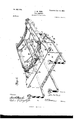
- Figure l is a central longitudinal vertical sectional view of the machine embodying my invention, the carriage and the carriage mechanism being omitted, as that forms no partof my present invention.
- Fig. 2 is a detached perspective view of the type-bar basket with only a portion of the type-bars shown in position therein to more clearly disclose the specific construction of the basket and the arrangement of the type-bars.
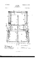
- Fig. 3 is a top plan view on line 3 3 of Fig. l, the type-basket being omitted to disclose the type-basket-shifting mechanism and the universal-frame mechanism for effecting the feed of ⁇ the carriage.
- Fig. 4 is a sectional view on the line e 4 of Fig. 3 and looking in the direction indicated by arrow. Fig.
- Fig. 5 is a sectional view on the line 5 5 of Fig. 3 and looking in .the direction indicated by arrow.
- Fig. G is a central vertical longi* tudinal sectional view through the type-bar basket, the type-bars and key-levers being 5o omitted.
- a horizontal frame A hav- Y ing at one end the vertically-arranged standard B, upon .which is supported a suitable carriage, and situated within the horizontal frame A below the carriage is a verticallyshifting type-bar basket O, in which are arranged the type-bars and the key-levers.
- one end of the type-bar basket consists of a block G, having grooves ZJ in its upper and lower sides, and located within these grooves are the type-bar division-plates c. Located between these division-plates are the type-bars H, which are'pivotally supported at their inner ends through the medium of a suitable rod d and carrying at their outer ends the type-bar block c, which contains the caps and small letters, as is well understood by those skilled in the art.
- a vertically-arranged plate I Projecting downward fromthe under side of the basket O at a point intermediate its ends is a vertically-arranged plate I, having in its under side a plurality of slots f, thus constituting a comb.
- the inner ends of the v L-shaped key-levers J rest in these slots f,
- the key-levers J are located at one side of the lower ends of the vertical portions Z of the levers M, and the key-levers are provided with laterally-projecting pins n, which project into suitable cam slots q, formed in the lowerends of the said vertical portions of the L'shaped levers M.
- the type-bars are arranged in the arc of a circle, and hence the intermediate levers M must be arranged to correspond with the type-bars. They are likewise arranged in the arc of a circle.
- the key-levers are arranged in a common horizontal plane, and owing to this arrangement of the key-levers it will be at once appreciated that the length of the vertical portionsl of the levers M will vary according to its location in order to reach 'the key-levers.
- the L-shaped intermediate levers M lying at or near the center of the type-bar basket have their vertical portions Zshort; but owing to the circular arrangement of the type-bars and these intermediate levers M it is necessary that the vertical portions Zof the levers M situated at opposite ends thereof be longer and be deected at a suitable point-for instance, at the point lr--to cause them to extend in a vertical plane.
- the form of spring consists of a doubled wire N, which passes through an opening s in the inner end of the key-lever, the ends of the said Wire passing through the openings t, formed inthe comb or plate I, the tension of the said spring serving to lift the outer free ends of the key-levers and to hold them in their normal positions.
- the means for shifting the basket vertically for the purpose of writing in caps consists of a transversely-arranged pivotal bar 2, which has rigidly secured thereto an outwardly-projecting arm 3.
- the free end of this arm 3 engages the under side of a suitable shoe 4, which is attached to the block G and extends downward and inward and has its opposite end connected with the downwardly-projecting comb or plate I and serves the additional function of assisting in supporting the plate.
- Rigidly connected to opposite ends of the said pivotal rod 2 and eX- tending forward are the arms 5, which are rigidly connected with a suitable counterweight 6.
- This counterweight 6 is here shown in the form of a flat sheet or plate of lead or similar material and serves, through the me dium of the arm 3, which is in. engagement with the inner free end of the vertically-movable type-bar basket C, to lighten the heft of the inner end of the said type-bar basket.
- shift-keys 7 Preferably I provide two shift-keys 7, the same being located at opposite sides of the machine, though, if desired, but one shift-key may be used.
- the inner ends of these shiftkeys 7 are pivotally connected to the horizontal frame A in any suitable manner at the points S and are intermediately connected with the outer ends of the arms 5 through the medium of suitable wire or other links 9.
- I provide any suitable form of locking lever or latch.
- I provide a lever 10, intermediately pivoted to the frame A, which lhas its lower end adapted to engage the upper edge of the-free end of one of thevarms 5 ofthe shifting frame, whereby when the said lever is moved inthe direction indicated by arrow in Fig. 4 it will cause a downward movement ofthe outer end of the shifting frame and 'ai corresponding upward movement of the inner end of the shifting frame, and' thus serve tobasket in the position tov lock the type-bar write in caps.
- the carriage-feed mechanism involves a universal frame, as is usual-in all type-writ ⁇ ers,fand thisuniversal frame as here shown is comprised of a pivotal rod'1 ⁇ 1, located at one end of the frame and below the carriage,v
- The'spa'ce mechanism here shown consists of a U-shaped frame 16, which has its ends ⁇ pivotally connected at the points 17 to suit-V able ears 18, which projectfrom the frame A.
- the means whereby the movement of the space-bar16'is transferred to the universal feed-frame consistsV of an arm'l20 ⁇ , which has its inner end 2l, as shown in Fig. 3,'loosely pivoted upon the rod 2 and vmovablelinde pendentthereon.
- This bar'20 curves upward and hasits outer end loosely inserted into an opening 22 of a depending arm 23, extending" be regulated relatively'to the movement ofV the key-levers, 'as some'operatorsdesire'an earlier feedof'the carriage in respect to the movement of the key-levers and the type-bar than others.
- This is ⁇ accomplished through the medium-of a bearing strip or plate 25,' which has one endf26'pivotally connected toy the said arm 20andits opposite end 26"con' structed to bevertically adjustable in respect to thesaid arm or lever 20through the mediumv of a slot and screw, as here shown at26;
- this bearingstrip orplate 25 will cause a correspondingmovement through the iengagement therewith of the barpli, constituting the inner end of the universal feeding-frame, andthu's cause acorresponding adj ustment'of the feed-dogs in relation to the carriage-rack.' Thisv vertical movement of the rod 14 willcause it to be nearer to or farther from the key-levers, thus regulatingthe period at which the feed of the carriage occurs relative to the Vmovement of the type-bars and key-levers.
- a typebaraction comprising a vsubstantially normally'horizontahy ⁇ arranged pivoted ⁇ type-bar,a key-lever located thereunder, a substantiallyhorizontallyv arranged member located between saidkey-le- .verand type-bar, the intermediate 'member operatively connected with said type-barand va direct cam connection between the'keyle verl land said horizontal member.
- a type-bar action comprising a substantially normally horizontally arranged pivoted'type-bar, having aprojectionfat its pivotal end, a keyleverlo'cated thereunder, and a rigid pivoted intermediate horizontalmemberhaving a socket at one end receiving the type-bar projection, and a connection at its opposite endY with said keylever;
- a type-bar action comprising a substantially normally horizontally arranged pivoted type-barhaving a projecytion at its pivoted end, a key-lever, and a pivoted intermediate member having at'one end a lsocketreceiving said type-bar projection, and a cam connection between its opposite end and said key-lever.
- a type-bar action comprising a substantially normally horizontally arranged pivoted type-bar, au intermediate lever located under the type-bar, the said intermediate lever having an inwardly-extendinghorizontal arm operatively connected with the pivoted end of. the type-bar, a key-lever located below the said intermediate lever, the intermediate lever having at its pivoted end a depending arm operatively connected with the key-lever.
- a type-bar action comprising a substantially normally horizontally arranged pivoted type-bar, an intermediate lever pivoted at one end near the free end of the type-bar, the free end of the intermediate lever directly operatively connected with the type-bar, and akey-lever located below the intermediate lever and directly operatively connected with the said intermediate lever.
- a type-bar action comprising a substantially normallyhorizontally arranged pivoted type-bar, an intermediate lever pivoted near but below the free end of the type-bar, the free end of the lever being operatively connected with the pivoted end of the type-bar, a key-lever below the intermediate lever and pivoted at a point below and between the end of the type-bar and the said lever, the pivoted end of the said intermediate lever being connected with the keylever at a point intermediate the ends of the latter.
- a type-bar action comprising a plurality of substantially normally horizontal pivoted type-bars arranged in the arc of a circle, a plurality of key-levers, a plurality of essentially L-shaped pivoted levers having horizontal and vertically-extending portions their horizontal portions operatively connected with the type-bars, and their vertical portions of various lengths, and cam connections of Vvarious pitches 'between the key-levers and the vertical portions of the said L-shaped levers.
- a type-bar action comprising a plurality of pivoted type-bars arranged in the arc of a circle, a plurality of pivoted L-shapcd levers located therebelowand arranged in a corresponding arc, the vertical portions of the L-shaped levers at either side of the central one increasing in length, a plurality of key-levers arranged in a common horizontal plane, and operative connections between the ends of said L-shaped levers,the type-bars and key-levers repectively.
- a type-baraction comprising a plurality of pivoted type-bars arranged in the arc of a circle, a plurality of pivoted L-shaped levers located therebelow and arranged in a corresponding arc, a plurality of key -levers located below the L- shaped levers, connections between the vertical portions of the L-shaped levers and the key-levers, all of said connections arranged in substantially the same horizontal plane, and connections between the horizontal ends of the said L-shaped levers and the type-bars.
- a type-bar action comprising a plurality of pivoted type-bars arranged in the arc of a circle, a plurality of pivoted L-shaped levers therebelow and arranged in a corresponding arc, the downwardly-projecting arms of the L-shaped levers at opposite sides of the central one being deflected and arranged in substantially a true vertical plane, a plurality of key-levers having a movement in substantially a true vertical plane, and operative connections between opposite ends of the L-shaped levers.
- a type-bar action comprising a plurality of pivoted type-bars arranged in the arc of a vertical circle, a plurality of L-shaped levers located therebelow and arranged in a corresponding arc, the said L-shaped levers pivoted at thejunction of the arms of the L, a plurality of key-levers, cam connections between the vertical arms of the L-shaped levers and the said key-levers, the cam connection consisting of cam-slots and pins engaging therein.
- a type-Writer the combination of a plurality of type-bars arranged in the arc of a vertical circle, a plurality of L-shaped levers having horizontal and vertically-projecting arms located therebelow, pivotal supports for the said levers at the junction of the arms constituting the L-shaped levers, an operative connection between the free ends of the horizontal arms and the type-bars, the vertical arms of the L-shaped levers provided with cani-shaped slots all of which are located in the same horizontal plane, and a plurality of key-levers located in a corresponding horizontal plane and provided with projections engaging the said cam-slots.
- a type-bar action comprising a frame, a plurality of type-bars pivoted therein and arranged in the arc of a vertical circle, a plurality of key-levers having their inner ends loosely connected with the said frame at a point below and between the ends of the type-bars, a plurality of L-shaped levers pivoted at the junction of the arms constituting the L-shaped levers, the said pivotal point located below and adjacent the free ends of the type-bars, and direct operative connections between the ends of the L-shapcd levers and the type-bars and key-levers respectively.
- a type-bar action comprising a vertically-movable frame, a plurality ot type-bars pivoted in one end thereof and arranged in the arc of a vertical circle, a plurality of L-shaped levers arranged in a corresponding arc and pivotally supported in the said frame at the junction of the arms constituting the L-shaped levers, the pivotal point located at a point between the ends of the said frame, a plurality of key-levers located below the L-shaped levers and having their inner ends loosely connected with the IOO ported in the same frame and having their inner ends loosely connected therewith, and a plurality of intermediate connecting members having one end connectedk with the pivotal ends of the type-bars and their opposite ends connected with the key-leversat points between the ends of the key-levers.
- a type-bar action comprising a vertically-shifting frame, a plurality of type-bars pivoted at one end of the frame and arrangedin the arc of a vertical circle, a plurality of keyleverslocated below the typebars and having their inner ends loosely supported by the said frame at a point intermediate the ends of the frame, the endV of the frame opposite the pivotal point of the typebars provided" with a depending key-leverguiding comb, and intermediate connections between the key-levers and the. type-bars.
- av substantiallyl khorizontally arranged verti cally-shifting type-bar action having a pivotalvsupport at one side of the center thereof, a key-lever for moving the said type-bar action upward, and a counterweight connected therewith and serving to assist the key-lever in moving the type-bar action upward.
- a substantially horizontal verticallyshifting type-baraction including type-bars, a pivotal connection therefor located at one side of its center, and a counterweight operatively conof the said type-bar action, and a counter-A weight operatively connected with the free end of said type-bar action, and exerting anY upward pressure thereon.
- a type-writer the combination of a substantially horizontal verticallyshifting type-bar action'pivotally supported at its outer portion, a counterweight operatively connected therewith to exert an upward tension on the free end thereof, and a compound key-lever connection for shifting the free end of said type-action.
Landscapes
- Toys (AREA)
Description
No. 697,384.' f Patented Apr. 8, |902.
J. W. PAUL.
' TYPE WRITER.'
(Application led May 1, 1901.)
("0 New 4 sheets-sheet l.
www CM... @@W
L 0 m oo, r. p A* d e t n Dv t .a P P.. mr.. .I A'. PR .W WE .w JT A". no 3, 7 9 6 0. N
(Application led May 1, 1901.)
4 Sheets-Sheet 2.
(No Model.)
Witness@ J. W. PAUL.
TYPE WRITER.
(Application led May 1, 1901,)
Patented Apr. 8, |902.
` No. 697,384. Patented Apr.8, |902.
J. W. PAUL.
TYPE WRITER.
(Applicazion med my 1, 1901.) (No Modal.) 4 Sheets-Sheet 4,
@M www UNiTEn STATES.
PATENT OFFICE.
JOHN WV. PAUL, OF KITTANNING, PENNSYLVANIA, ASSIGNOR TO PITTS- BURG IVRITING MACHINE COMPANY, OF PITTSBURG, PENNSYLVANIA.
TYPE-WRITER.
SPECFXGATIGN forming part of Letters Patent No. 697,384, dated April 8, 1902. Application filed May 1, 1901. Serial No. 58,377. (No model.)
To all whom, t may concern:
Beit known that I, JOHN W. PAUL, a citizen of the United States, residing at Kittanning, in the county of Armstrong and State of Pennsylvania, have invented new and useful Improvements in Type-Writers, of which the following is a specification.
My invention relates to improvements in type-writers, and pertains to a machine of the visible-writing type and wherein the typebars are arranged in a substantially horizontal basket. v
The primary object of this invention is to provide a simple arrangement and construction of the type-bar action wherebya straight, easy, and practically uniform touch is effected.
A further object of my invention is to so construct the shifting mechanism for the vertically-movable type-bar basket that a quickacting and easy-touch shift is provided.
A further object of this invention relates to the construction and arrangement of the several parts of the mechanism hereinafter shown and described whereby an improved machine of the visible-writin g type is produced.
In the accompanying drawings, Figure l is a central longitudinal vertical sectional view of the machine embodying my invention, the carriage and the carriage mechanism being omitted, as that forms no partof my present invention. Fig. 2 is a detached perspective view of the type-bar basket with only a portion of the type-bars shown in position therein to more clearly disclose the specific construction of the basket and the arrangement of the type-bars. Fig. 3 is a top plan view on line 3 3 of Fig. l, the type-basket being omitted to disclose the type-basket-shifting mechanism and the universal-frame mechanism for effecting the feed of `the carriage. Fig. 4 is a sectional view on the line e 4 of Fig. 3 and looking in the direction indicated by arrow. Fig. 5 is a sectional view on the line 5 5 of Fig. 3 and looking in .the direction indicated by arrow. Fig. G is a central vertical longi* tudinal sectional view through the type-bar basket, the type-bars and key-levers being 5o omitted.
In a machine of the character herein shown there is essentially a horizontal frame A, hav- Y ing at one end the vertically-arranged standard B, upon .which is supported a suitable carriage, and situated within the horizontal frame A below the carriage is a verticallyshifting type-bar basket O, in which are arranged the type-bars and the key-levers.
The combined type-bar and key-lever bas-V Referring now to the construction and ar- `rangement of the type-bar basket, the typebars, and the key-levers, it will be noticed that one end of the type-bar basket consists of a block G, having grooves ZJ in its upper and lower sides, and located within these grooves are the type-bar division-plates c. Located between these division-plates are the type-bars H, which are'pivotally supported at their inner ends through the medium of a suitable rod d and carrying at their outer ends the type-bar block c, which contains the caps and small letters, as is well understood by those skilled in the art.
Projecting downward fromthe under side of the basket O at a point intermediate its ends is a vertically-arranged plate I, having in its under side a plurality of slots f, thus constituting a comb. The inner ends of the v L-shaped key-levers J rest in these slots f,
andthe outer portions of the key-levers are guided and moved in vertically-arran ged slots g', formed in a downwardly-projecting plate K, located at the opposite or outer end of the basket to that at which the .type-bars H are pivoted.
In a type-writer ofthe character here shown it is necessary that the type-bars be arranged in the arc of a circle and radially in respect thereto, and it is the primary object of my present invention to so construct and arrange the key-levers and the intermediate mechan-j /IOO ism between the key-levers and the typebars that although the type-bars travel in radii to the arc of a circle in which they are arranged, yet the key-levers will move in a vertical plane. This result is accomplished through the medium of the intermediate essentially L-shaped levers M, carrying at their inner ends suitable sockets t', adapted to receive and act upon the pivotal ends of the type-bars in a manner which is well known to those skilled in the art and need not be specifically described. At the intersection of the vertical portion Z of the L-shaped levers M a pivotal rod or other suitable pivotal support m passes for the purpose of forming a pivotal connection for the said L-shaped levers. The key-levers J are located at one side of the lower ends of the vertical portions Z of the levers M, and the key-levers are provided with laterally-projecting pins n, which project into suitable cam slots q, formed in the lowerends of the said vertical portions of the L'shaped levers M. By means of this construction when a key-lever is depressed the pin n thereof will by its engagement with the cam-slot q of the intermediate lever M cause its inner free end to move upward, and this upward movement will cause the type-bar H to be thrown up and against the printing-roller, as will be readily understood.
As before stated,the type-bars are arranged in the arc of a circle, and hence the intermediate levers M must be arranged to correspond with the type-bars. They are likewise arranged in the arc of a circle. The key-levers are arranged in a common horizontal plane, and owing to this arrangement of the key-levers it will be at once appreciated that the length of the vertical portionsl of the levers M will vary according to its location in order to reach 'the key-levers. On account of this construction the L-shaped intermediate levers M lying at or near the center of the type-bar basket have their vertical portions Zshort; but owing to the circular arrangement of the type-bars and these intermediate levers M it is necessary that the vertical portions Zof the levers M situated at opposite ends thereof be longer and be deected at a suitable point-for instance, at the point lr--to cause them to extend in a vertical plane.
Owing to the fact that the vertical portions of the levers M are of varying lengths and the desirability of having a uniform downward movement to the key-levers the inclination of the cam-slots q in the vertical portions of the intermediate levers M must of necessity vary. For instance, by referring to Fig. 2 it will be seen that the said slot q' in the central lever M is but slightly inclined, while the slots q in the end intermediate levers M are at a considerable angle. This is so for the reason that the longer vertical portions of the intermediate levers M must travel farther than the short portions of some of the other levers M in order to give the inner free ends the key-levers and assisting in the quick return to their normal positions I provide a spring for each of the key-levers. As here shown the form of spring consists of a doubled wire N, which passes through an opening s in the inner end of the key-lever, the ends of the said Wire passing through the openings t, formed inthe comb or plate I, the tension of the said spring serving to lift the outer free ends of the key-levers and to hold them in their normal positions.
The means for shifting the basket vertically for the purpose of writing in caps consists of a transversely-arranged pivotal bar 2, which has rigidly secured thereto an outwardly-projecting arm 3. The free end of this arm 3 engages the under side of a suitable shoe 4, which is attached to the block G and extends downward and inward and has its opposite end connected with the downwardly-projecting comb or plate I and serves the additional function of assisting in supporting the plate. Rigidly connected to opposite ends of the said pivotal rod 2 and eX- tending forward are the arms 5, which are rigidly connected with a suitable counterweight 6. This counterweight 6 is here shown in the form of a flat sheet or plate of lead or similar material and serves, through the me dium of the arm 3, which is in. engagement with the inner free end of the vertically-movable type-bar basket C, to lighten the heft of the inner end of the said type-bar basket.
Preferably I provide two shift-keys 7, the same being located at opposite sides of the machine, though, if desired, but one shift-key may be used. The inner ends of these shiftkeys 7 are pivotally connected to the horizontal frame A in any suitable manner at the points S and are intermediately connected with the outer ends of the arms 5 through the medium of suitable wire or other links 9.
When t-he typefbar basket is in position, its inner end, being in engagement with the inner free end of the arm 3, lifts the outer free ends of the arms 5 and in Vturn the counterweight (5, which is rigidly connected therewith, and through the medium of the links 9 also lifts the shift-keys 7 to their normal positions. A downward pressure upon either one of the shift-keys 7 will canse a corresponding downward movement of the counterweight and the free ends of the arms 5, and this in turn will lift the inner free 'end of the arm 3 and cause the lifting of the inner free end of the vertically-shifting type-bar basket.
ICO
For the purpose of enabling the'type-bar basket to be locked in its shifted position when writing a word or asentence in caps I provide any suitable form of locking lever or latch. As here shown I provide a lever 10, intermediately pivoted to the frame A, which lhas its lower end adapted to engage the upper edge of the-free end of one of thevarms 5 ofthe shifting frame, whereby when the said lever is moved inthe direction indicated by arrow in Fig. 4 it will cause a downward movement ofthe outer end of the shifting frame and 'ai corresponding upward movement of the inner end of the shifting frame, and' thus serve tobasket in the position tov lock the type-bar write in caps.
-The carriage-feed mechanism involves a universal frame, as is usual-in all type-writ` ers,fand thisuniversal frame as here shown is comprised of a pivotal rod'1`1, located at one end of the frame and below the carriage,v
outwardly-extending armsL 12, which are rigidly connected with vthe said rod 11, and a straight horizontally-arrangedYbar 14, which extends directly under the key-levers J and adapted to be engaged thereby when the keylevers 'are 'depressed' foi` the' purpose of oscil-v lating the rod 11, to which is rigidly connected the dog-supporting Iframe v15. From this descriptionit will 'be noticed that the uni! versal feeding-'frame is of'a rectangular -character and presents a perfectly-horizontal surface to the under side ofthe key-levers J and that there is -no'lateral-'or grinding action between the key-levers and the universal frame in the movement of the type-action of the machine.
'The'spa'ce mechanismhere shown consists of a U-shaped frame 16, which has its ends` pivotally connected at the points 17 to suit-V able ears 18, which projectfrom the frame A. The means whereby the movement of the space-bar16'is transferred to the universal feed-frame consistsV of an arm'l20`, which has its inner end 2l, as shown in Fig. 3,'loosely pivoted upon the rod 2 and vmovablelinde pendentthereon. This bar'20 curves upward and hasits outer end loosely inserted into an opening 22 of a depending arm 23, extending" be regulated relatively'to the movement ofV the key-levers, 'as some'operatorsdesire'an earlier feedof'the carriage in respect to the movement of the key-levers and the type-bar than others. This is `accomplished through the medium-of a bearing strip or plate 25,' which has one endf26'pivotally connected toy the said arm 20andits opposite end 26"con' structed to bevertically adjustable in respect to thesaid arm or lever 20through the mediumv of a slot and screw, as here shown at26;
The vertical movement of this bearingstrip orplate 25 will cause a correspondingmovement through the iengagement therewith of the barpli, constituting the inner end of the universal feeding-frame, andthu's cause acorresponding adj ustment'of the feed-dogs in relation to the carriage-rack.' Thisv vertical movement of the rod 14 willcause it to be nearer to or farther from the key-levers, thus regulatingthe period at which the feed of the carriage occurs relative to the Vmovement of the type-bars and key-levers.
I do not limit'myself' to thespecilic construction and specific arrangement of the parts herein enumerated, as these may be varied'by those skilled in the art withoutmaterially. affecting the spirit or scope of myinvention. f
I-Iaving thus described myinvention, what I claimjand desire to secure by Letters-Patent, isl f Y 1. In atype-writer, a typebaraction comprising a vsubstantially normally'horizontahy `arranged pivoted` type-bar,a key-lever located thereunder, a substantiallyhorizontallyv arranged member located between saidkey-le- .verand type-bar, the intermediate 'member operatively connected with said type-barand va direct cam connection between the'keyle verl land said horizontal member.
Y2. In a type-writer, a type-bar action comprising a substantially normally horizontally arranged pivoted'type-bar, having aprojectionfat its pivotal end, a keyleverlo'cated thereunder, anda rigid pivoted intermediate horizontalmemberhaving a socket at one end receiving the type-bar projection, and a connection at its opposite endY with said keylever;
In 'a type-writer, a type-bar action comprising a substantially normally horizontally arranged pivoted type-barhaving a projecytion at its pivoted end, a key-lever, and a pivoted intermediate member having at'one end a lsocketreceiving said type-bar projection, and a cam connection between its opposite end and said key-lever. w
4'. In a type-writer, a type-bar action com` .pri'sing a substantiallynormally horizontally arranged pivoted type-bar, ka keyLlever," an essentially Lishaped Vintermedia tely-'pivot'e'dle- ICO IIO
the type-bar projection, and the vertical arm operatively connected with the key-lever.
G. In a type-writer, a type-bar action comprising a substantially normally horizontally arranged pivoted type-bar, au intermediate lever located under the type-bar, the said intermediate lever having an inwardly-extendinghorizontal arm operatively connected with the pivoted end of. the type-bar, a key-lever located below the said intermediate lever, the intermediate lever having at its pivoted end a depending arm operatively connected with the key-lever.
7. In a type-writer, a type-bar action comprising a substantially normally horizontally arranged pivoted type-bar, an intermediate lever pivoted at one end near the free end of the type-bar, the free end of the intermediate lever directly operatively connected with the type-bar, and akey-lever located below the intermediate lever and directly operatively connected with the said intermediate lever.
S. In a type-writer, a type-bar action comprising a substantially normallyhorizontally arranged pivoted type-bar, an intermediate lever pivoted near but below the free end of the type-bar, the free end of the lever being operatively connected with the pivoted end of the type-bar, a key-lever below the intermediate lever and pivoted at a point below and between the end of the type-bar and the said lever, the pivoted end of the said intermediate lever being connected with the keylever at a point intermediate the ends of the latter.
9. In a type-writer, a type-bar action comprising a plurality of substantially normally horizontal pivoted type-bars arranged in the arc of a circle, a plurality of key-levers, a plurality of essentially L-shaped pivoted levers having horizontal and vertically-extending portions their horizontal portions operatively connected with the type-bars, and their vertical portions of various lengths, and cam connections of Vvarious pitches 'between the key-levers and the vertical portions of the said L-shaped levers.
10. In a type-writer, a type-bar action comprising a plurality of pivoted type-bars arranged in the arc of a circle, a plurality of pivoted L-shapcd levers located therebelowand arranged in a corresponding arc, the vertical portions of the L-shaped levers at either side of the central one increasing in length, a plurality of key-levers arranged in a common horizontal plane, and operative connections between the ends of said L-shaped levers,the type-bars and key-levers repectively.
1l. In a type-writer, a type-baraction comprising a plurality of pivoted type-bars arranged in the arc of a circle, a plurality of pivoted L-shaped levers located therebelow and arranged in a corresponding arc, a plurality of key -levers located below the L- shaped levers, connections between the vertical portions of the L-shaped levers and the key-levers, all of said connections arranged in substantially the same horizontal plane, and connections between the horizontal ends of the said L-shaped levers and the type-bars.
12. In a type-writer, a type-bar action comprising a plurality of pivoted type-bars arranged in the arc of a circle, a plurality of pivoted L-shaped levers therebelow and arranged in a corresponding arc, the downwardly-projecting arms of the L-shaped levers at opposite sides of the central one being deflected and arranged in substantially a true vertical plane, a plurality of key-levers having a movement in substantially a true vertical plane, and operative connections between opposite ends of the L-shaped levers.
13. In a type-writer, a type-bar action comprising a plurality of pivoted type-bars arranged in the arc of a vertical circle, a plurality of L-shaped levers located therebelow and arranged in a corresponding arc, the said L-shaped levers pivoted at thejunction of the arms of the L, a plurality of key-levers, cam connections between the vertical arms of the L-shaped levers and the said key-levers, the cam connection consisting of cam-slots and pins engaging therein.
lat. In a type-Writer, the combination of a plurality of type-bars arranged in the arc of a vertical circle, a plurality of L-shaped levers having horizontal and vertically-projecting arms located therebelow, pivotal supports for the said levers at the junction of the arms constituting the L-shaped levers, an operative connection between the free ends of the horizontal arms and the type-bars, the vertical arms of the L-shaped levers provided with cani-shaped slots all of which are located in the same horizontal plane, and a plurality of key-levers located in a corresponding horizontal plane and provided with projections engaging the said cam-slots.
15. In a type-writer, a type-bar action comprising a frame, a plurality of type-bars pivoted therein and arranged in the arc of a vertical circle, a plurality of key-levers having their inner ends loosely connected with the said frame at a point below and between the ends of the type-bars, a plurality of L-shaped levers pivoted at the junction of the arms constituting the L-shaped levers, the said pivotal point located below and adjacent the free ends of the type-bars, and direct operative connections between the ends of the L-shapcd levers and the type-bars and key-levers respectively.
16. In a type-writer, a type-bar action comprising a vertically-movable frame, a plurality ot type-bars pivoted in one end thereof and arranged in the arc of a vertical circle, a plurality of L-shaped levers arranged in a corresponding arc and pivotally supported in the said frame at the junction of the arms constituting the L-shaped levers, the pivotal point located at a point between the ends of the said frame, a plurality of key-levers located below the L-shaped levers and having their inner ends loosely connected with the IOO ported in the same frame and having their inner ends loosely connected therewith, and a plurality of intermediate connecting members having one end connectedk with the pivotal ends of the type-bars and their opposite ends connected with the key-leversat points between the ends of the key-levers.
1S. In a type-writer, a type-bar action comprisinga vertically-shifting frame, a plurality of type-bars pivoted at one end of the frame and arrangedin the arc of a vertical circle, a plurality of keyleverslocated below the typebars and having their inner ends loosely supported by the said frame at a point intermediate the ends of the frame, the endV of the frame opposite the pivotal point of the typebars provided" with a depending key-leverguiding comb, and intermediate connections between the key-levers and the. type-bars.
19. In a type-writer, the combination of a vertically-shifting type-loar action,and a counterweight operatively connected therewith and of less heft than the heft of the type-bar action and serving to assistV in moving the type-bar action vertically.
20. In a type-writer, the combination of av substantiallyl khorizontally arranged verti cally-shifting type-bar action having a pivotalvsupport at one side of the center thereof, a key-lever for moving the said type-bar action upward, and a counterweight connected therewith and serving to assist the key-lever in moving the type-bar action upward.
21. In a type-writer the combination of a substantially horizontal verticallyshifting type-baraction including type-bars, a pivotal connection therefor located at one side of its center, and a counterweight operatively conof the said type-bar action, and a counter-A weight operatively connected with the free end of said type-bar action, and exerting anY upward pressure thereon.
23. In a type-writer the combination of a` Substantially i horizontal vertically shifting 'type-bar action, a counterweight connected therewith, a key-lever, `and a connection be tween the type-bar action and the key-lever at a point intermediate the latter.
24. In a type-writer the combination ofa substantially horizontal verticallyshifting type-bar action'pivotally supported at its outer portion, a counterweight operatively connected therewith to exert an upward tension on the free end thereof, and a compound key-lever connection for shifting the free end of said type-action.
25. In a type-writerthe combination of a substantially horizontal vertically shifting 'type-bar action pivotallyA supported ratits outer portion, and a compound key-lever connected therewith and constructed to lift the type-action when the key-lever is depressed.
26. In a type-writer the combination of a substantially horizontal vertically-shifting pivoted type-bar action, an intermediatelypivoted member having one end operatively connected with the freeend of said type-action, a shifting lever pivoted at one end and having aninterinediate connection with the opposite end'of said intermediately-pivoted member.
27. In a type-writer the combination of a substantially horizontal vertically shifting pivoted type-bar action, an intermediatelypivoted member having 011e end operatively vconnected with the free end of said type-bar action, an inwardly-extendingshift-lever havingits inner end-independently pivotally supported, and a connection between the opposite end of the intermediately-pivoted.member and the shift-lever at apoint intermediate the ends of the latter. Y
28. In a type-writer, the combination of a substantially horizontal vertically-shifting pivoted type-bar action, an vintermediatelypivoted member having one end operatively ,connectedwith the free end of the said typeaction,v a shift-lever pivoted at one end to an independentsupport, and a link connected to the opposite end of the intermediate mem- ICO ber and to the shift-lever ata pointintermefdiate the ends of the latter.
29. In a type-writer the combination of a substantially horizontal vertically-shifting pivoted type-bar action, an intermediatelypivoted member having one endwoperatively connectedwith the free end of said type-action, and a counterweight connected withthe opposite end ofsaid intermediately-pivoted member and serving to depress the end of said lever with which it is connected.
30. In a type-writer the combination of a substantially horizontal vertically-shifting pivoted type-action, an intermediately-pivoted member having one end operatively connected with the free end of said type-action, a counterweight in the formvof a sheet4 attached to and extending substantiallyparallel the opposite end of said intermediatelypivoted member.
31. In a type-writer the combination of a type-action including a plurality of key-levers, a universal carriage-feed member, a space-bar, and a lever pivotedatl its inner end-intermediately engaging said universah' type-bars, a universal earriagefeed member In testimony whereof I have hereunto set adapted to be engaged thereby, a space-bar my hand in the presence of two subscribing pivotally connected with said frame, a lever Witnesses.
extending over said universal feed member JOHN NV. PAUL. 5 and pivotnlly supported at its inner end, the Witnesses:
outer end of seid lever connected with the R. L. RALSTON,
space-bar. P. E. WHITNEY.
Priority Applications (1)
| Application Number | Priority Date | Filing Date | Title |
|---|---|---|---|
| US5837701A US697384A (en) | 1901-05-01 | 1901-05-01 | Type-writer. |
Applications Claiming Priority (1)
| Application Number | Priority Date | Filing Date | Title |
|---|---|---|---|
| US5837701A US697384A (en) | 1901-05-01 | 1901-05-01 | Type-writer. |
Publications (1)
| Publication Number | Publication Date |
|---|---|
| US697384A true US697384A (en) | 1902-04-08 |
Family
ID=2765920
Family Applications (1)
| Application Number | Title | Priority Date | Filing Date |
|---|---|---|---|
| US5837701A Expired - Lifetime US697384A (en) | 1901-05-01 | 1901-05-01 | Type-writer. |
Country Status (1)
| Country | Link |
|---|---|
| US (1) | US697384A (en) |
-
1901
- 1901-05-01 US US5837701A patent/US697384A/en not_active Expired - Lifetime
Similar Documents
| Publication | Publication Date | Title |
|---|---|---|
| US697384A (en) | Type-writer. | |
| US556460A (en) | Type-writing machine | |
| US966955A (en) | Type-writing machine. | |
| US626915A (en) | Type-writer | |
| US1118664A (en) | Shift-key attachment for type-writing machines. | |
| US1028214A (en) | Type-writing machine. | |
| US807449A (en) | Type-writing machine. | |
| US947253A (en) | Type-writing machine. | |
| US750572A (en) | beyerlen | |
| US415526A (en) | Type-writing machine | |
| US984654A (en) | Type-writing machine. | |
| US1768155A (en) | Typewriter | |
| US458522A (en) | davis | |
| US727607A (en) | Key-action for type-writing machines. | |
| US967916A (en) | Writing-machine. | |
| US739622A (en) | Type-writing machine. | |
| US779005A (en) | Type-writing machine. | |
| US707882A (en) | Type-writing machine. | |
| US668713A (en) | Type-writing machine. | |
| US697250A (en) | Writing-machine. | |
| US996538A (en) | Type-writing machine. | |
| US1049291A (en) | Type-writing machine. | |
| US737742A (en) | Support for links of type-writer actions. | |
| US1010852A (en) | Type-writing machine. | |
| US758982A (en) | Type-writing machine. |