US6964339B2 - Shock absorbing container - Google Patents

Shock absorbing container Download PDF

Info

Publication number
US6964339B2
US6964339B2 US10/320,010 US32001002A US6964339B2 US 6964339 B2 US6964339 B2 US 6964339B2 US 32001002 A US32001002 A US 32001002A US 6964339 B2 US6964339 B2 US 6964339B2
Authority
US
United States
Prior art keywords
container
sheet member
outer container
walls
linear
Prior art date
Legal status (The legal status is an assumption and is not a legal conclusion. Google has not performed a legal analysis and makes no representation as to the accuracy of the status listed.)
Expired - Fee Related
Application number
US10/320,010
Other versions
US20040112788A1 (en
Inventor
John S. Meyer
Current Assignee (The listed assignees may be inaccurate. Google has not performed a legal analysis and makes no representation or warranty as to the accuracy of the list.)
Seiko Epson Corp
Original Assignee
Seiko Epson Corp
Priority date (The priority date is an assumption and is not a legal conclusion. Google has not performed a legal analysis and makes no representation as to the accuracy of the date listed.)
Filing date
Publication date
Application filed by Seiko Epson Corp filed Critical Seiko Epson Corp
Priority to US10/320,010 priority Critical patent/US6964339B2/en
Assigned to EPSON PORTLAND, INC. reassignment EPSON PORTLAND, INC. ASSIGNMENT OF ASSIGNORS INTEREST (SEE DOCUMENT FOR DETAILS). Assignors: MEYER, JOHN S.
Assigned to SEIKO EPSON CORPORATION reassignment SEIKO EPSON CORPORATION ASSIGNMENT OF ASSIGNORS INTEREST (SEE DOCUMENT FOR DETAILS). Assignors: EPSON PORTLAND, INC.
Publication of US20040112788A1 publication Critical patent/US20040112788A1/en
Application granted granted Critical
Publication of US6964339B2 publication Critical patent/US6964339B2/en
Anticipated expiration legal-status Critical
Expired - Fee Related legal-status Critical Current

Links

Images

Classifications

    • BPERFORMING OPERATIONS; TRANSPORTING
    • B65CONVEYING; PACKING; STORING; HANDLING THIN OR FILAMENTARY MATERIAL
    • B65DCONTAINERS FOR STORAGE OR TRANSPORT OF ARTICLES OR MATERIALS, e.g. BAGS, BARRELS, BOTTLES, BOXES, CANS, CARTONS, CRATES, DRUMS, JARS, TANKS, HOPPERS, FORWARDING CONTAINERS; ACCESSORIES, CLOSURES, OR FITTINGS THEREFOR; PACKAGING ELEMENTS; PACKAGES
    • B65D77/00Packages formed by enclosing articles or materials in preformed containers, e.g. boxes, cartons, sacks or bags
    • B65D77/04Articles or materials enclosed in two or more containers disposed one within another
    • B65D77/0413Articles or materials enclosed in two or more containers disposed one within another the inner and outer containers being rigid or semi-rigid and the outer container being of polygonal cross-section formed by folding or erecting one or more blanks, e.g. carton
    • B65D77/042Articles or materials enclosed in two or more containers disposed one within another the inner and outer containers being rigid or semi-rigid and the outer container being of polygonal cross-section formed by folding or erecting one or more blanks, e.g. carton the inner container being of polygonal cross-section formed by folding or erecting one or more blanks, e.g. carton
    • BPERFORMING OPERATIONS; TRANSPORTING
    • B65CONVEYING; PACKING; STORING; HANDLING THIN OR FILAMENTARY MATERIAL
    • B65DCONTAINERS FOR STORAGE OR TRANSPORT OF ARTICLES OR MATERIALS, e.g. BAGS, BARRELS, BOTTLES, BOXES, CANS, CARTONS, CRATES, DRUMS, JARS, TANKS, HOPPERS, FORWARDING CONTAINERS; ACCESSORIES, CLOSURES, OR FITTINGS THEREFOR; PACKAGING ELEMENTS; PACKAGES
    • B65D81/00Containers, packaging elements, or packages, for contents presenting particular transport or storage problems, or adapted to be used for non-packaging purposes after removal of contents
    • B65D81/02Containers, packaging elements, or packages, for contents presenting particular transport or storage problems, or adapted to be used for non-packaging purposes after removal of contents specially adapted to protect contents from mechanical damage
    • B65D81/05Containers, packaging elements, or packages, for contents presenting particular transport or storage problems, or adapted to be used for non-packaging purposes after removal of contents specially adapted to protect contents from mechanical damage maintaining contents at spaced relation from package walls, or from other contents
    • YGENERAL TAGGING OF NEW TECHNOLOGICAL DEVELOPMENTS; GENERAL TAGGING OF CROSS-SECTIONAL TECHNOLOGIES SPANNING OVER SEVERAL SECTIONS OF THE IPC; TECHNICAL SUBJECTS COVERED BY FORMER USPC CROSS-REFERENCE ART COLLECTIONS [XRACs] AND DIGESTS
    • Y10TECHNICAL SUBJECTS COVERED BY FORMER USPC
    • Y10STECHNICAL SUBJECTS COVERED BY FORMER USPC CROSS-REFERENCE ART COLLECTIONS [XRACs] AND DIGESTS
    • Y10S206/00Special receptacle or package
    • Y10S206/825Recoil-type retainer

Definitions

  • the present invention relates to the field of containers and more particularly to a shock absorbing container.
  • a container When stacked or handled, a container can experience forces or shocks in the side-to-side or front-to-back (“horizontal”) direction or in the up or down (“vertical”) direction. Fragile articles stored in the container, such as circuit boards, can be damaged as a result of forces or shocks. Thus, there is a need to protect articles stored in the container from forces and shocks.
  • a cellular structure can be placed in the interior of a container, such as the exemplary cellular structure shown in FIG. 1 .
  • FIG. 2 shows the cellular structure of FIG. 1 placed within a container.
  • a number of articles may be placed in the shown cellular structure; typically, one article per cell.
  • articles are not placed in the outer cells.
  • the outer cells serve to protect articles in the inner cells from horizontal forces or shocks.
  • the cellular structure by itself, however, does not provide protection from vertical forces or shocks.
  • a polymer foam cushion may be employed at the top or the bottom of the container.
  • the cellular structure shown in FIGS. 1–2 has a recessed rectangular area that is adapted to receive a rectangular polymer foam cushion, such as the one shown in FIG. 3 .
  • FIG. 4 shows, in cross-section, the container and cellular structure of FIGS. 1–2 which additionally includes the polymer foam cushion of FIG. 3 .
  • Polymer foam is expensive.
  • recycling polymer foam is complicated and recycling facilities are not always available. Further, containers that employ polymer foam cushions may be difficult to assemble.
  • FIGS. 5–6 show another method for protecting the contents of a container from vertical forces and shocks.
  • FIG. 5 shows an exemplary folded corrugated board that may be employed inside a container.
  • FIG. 6 shows a cross-sectional view of a container having a pair of folded corrugated boards. The dashed line represents one or more articles in the container.
  • Each folded corrugated board includes a vertical section parallel to a container wall that remains stationary, an end section that projects over the article at an angle above the horizontal, and a fold or score at the junction of the two sections.
  • the end section bends inward about the fold providing cushioning.
  • the end section can contact the articles in the container. This can result in the force or shock being transferred directly to the articles.
  • containers that employ folded corrugated board may be difficult to assemble.
  • a shock absorbing container for packaging one or more articles, including an outer container, a sheet member, and an article container.
  • the outer container has a closed configuration for shipping the articles.
  • the outer container includes an inner top surface and an opposed inner bottom surface that are substantially fixedly spaced apart in a vertical axis.
  • the sheet member has a bottom surface and at least one preformed foldable portion. The preformed foldable portion is folded away from the bottom surface of the sheet member and terminates at a free distal edge. The free distal edge bears against the top surface of the outer container when receiving vertically directed forces transmitted by the top surface.
  • the article container is disposed inside the outer container and is for receiving articles.
  • the article container includes a plurality of intersecting walls so that, when receiving vertically directed forces transmitted by the sheet member at least two of the walls have upper ends bearing against the bottom surface of the sheet member and lower ends bearing against the bottom surface of the outer container.
  • the walls by intersecting with each other, support one another to maintain the walls upright so that the walls are enabled to support the vertically directed forces transmitted by the sheet member.
  • the sheet member is formed of corrugated paperboard.
  • FIG. 1 illustrates a prior art cellular structure.
  • FIG. 2 illustrates the cellular structure of FIG. 1 within a container.
  • FIG. 3 illustrates a prior art polymer foam cushion.
  • FIG. 4 is a cross-sectional view the polymer foam cushion of FIG. 3 disposed within the cellular structure and container of FIG. 2 .
  • FIG. 5 illustrates a prior art folded corrugated board.
  • FIG. 6 is a cross-sectional view of a pair of the folded corrugated boards of FIG. 5 disposed within a container.
  • FIG. 7 illustrates a shock absorbing container assembly that includes an outer container and an article container having notched and reverse notched partitions according to the present invention.
  • FIG. 8 illustrates the article container of FIG. 7 .
  • FIG. 9 shows a reverse notched partition of the article container of FIG. 8
  • FIG. 10 shows a notched partition of the article container of FIG. 8 .
  • FIG. 11 illustrates an alternative preferred embodiment of an outer container.
  • FIG. 12 illustrates a sheet member according to the present invention.
  • FIG. 13 illustrates the sheet member of FIG. 12 in a folded arrangement.
  • FIG. 14 illustrates an alternate embodiment of a sheet member according to the present invention.
  • FIG. 15 illustrates the sheet member of FIG. 14 in a folded arrangement.
  • FIG. 16 illustrates two of the sheet members of FIG. 12 disposed within an article container according to the present invention.
  • FIG. 17 is a cross-sectional view of the sheet members and article holding container of FIG. 16 .
  • FIGS. 1–6 This detailed description of a preferred embodiment is organized as follows: First, the exemplary prior art packaging methods shown in FIGS. 1–6 are described in detail. Second, the present invention is discussed with reference to FIGS. 7–17 . Finally, the meaning of some of the terms and phrases used herein are discussed.
  • FIG. 1 illustrates an exemplary cellular structure 20 .
  • FIG. 2 shows the cellular structure 20 of FIG. 1 within a container 22 .
  • a number of articles may be placed in the shown cellular structure 20 ; typically, one article per inner cell 24 .
  • articles are not placed in the outer cells 26 .
  • the cellular structure 20 does not provide protection from vertical forces or shocks.
  • FIG. 3 illustrates a polymer foam cushion 28 that may be employed at the top or the bottom of a container to protect the contents from vertical forces and shocks.
  • the cellular structure shown in FIGS. 1–2 has a recessed rectangular area 30 that is adapted to receive the polymer foam cushion 28 .
  • Polymer foam is expensive and can be difficult to recycle.
  • FIG. 4 shows, in cross-section, the cellular structure 20 , the container 22 , and the polymer foam cushion 28 disposed in recessed area 30 .
  • FIG. 5 illustrates an exemplary folded corrugated board 32 that may be employed inside a container 40 .
  • the folded corrugated board 32 includes a vertical section 34 , an end section 36 , and a fold 38 at the junction of the two sections.
  • FIG. 6 shows a cross-sectional view of a container 40 having a pair of folded corrugated boards 32 .
  • the dashed line represents an article 42 within the container.
  • the vertical sections 34 of each folded corrugated board 32 are parallel to the side walls of the container 40 .
  • the end section 36 projects over the article 42 at an angle above the horizontal. When the top side 46 receives a vertical force or shock, the end section 36 bends down about the fold 38 in the direction of arrows 48 . When the end section 36 bends down, it can contact the article 42 . If end section 36 does contact the article 42 , the vertical force or shock will be transferred to the article 42 .
  • FIGS. 7–16 preferred embodiments of a shock absorbing container assembly according to the present invention are illustrated.
  • the present invention provides protection from vertical forces and shocks without relying on polymer foam. Moreover, vertical forces or shocks are not transferred to the article.
  • the shock absorbing container assembly includes three components: an outer container, a sheet member, and an article container.
  • FIG. 7 illustrates a preferred embodiment of a shock absorbing container assembly 50 that includes one preferred embodiment of an outer container 52 having four side walls 54 , a bottom side 56 , and a lid 58 .
  • the side walls 54 define a vertical (“y”) axis.
  • the outer container 52 also includes an inner bottom surface 62 (not shown).
  • the inner bottom surface 62 is opposite bottom side 56 .
  • the shown lid 58 is removable.
  • the lid 58 may be hingedly attached to the outer container 52 .
  • the shock absorbing container assembly 50 has two configurations: a closed configuration when the lid 58 is disposed as a top side of the outer container 52 and an open configuration when the lid 58 is not so disposed. In the closed configuration, the outer container 52 additionally includes an inner top surface 60 .
  • the inner top surface 60 is opposite a top side 64 of the lid 58 .
  • the inner top surface 60 and the inner bottom surface 62 are substantially fixedly spaced apart in the vertical axis by a distance defined by the height of the side walls 54 .
  • One preferred embodiment of an article container 66 is disposed within the outer container 52 .
  • FIG. 8 illustrates the article container 66 .
  • the article container 66 has a plurality of intersecting walls. The intersection of one wall with another maintains both walls in an upright position. Each wall provides support to the other by means of the coupling provided by the intersection. For example, if a vertical force or shock is exerted on an upper end of a wall, the wall will maintain its upright position through the support provided by the intersection. Of course, there is a limit to the amount of support that can be provided and normally the intersection of two corrugated board walls will not prevent crushing should a sufficient vertical force be applied.
  • the shown article container 66 is assembled from two types of partitions that are shown in FIGS. 9–10 .
  • FIG. 9 shows a reverse notched partition 68 .
  • FIG. 10 shows a notched partition 70 .
  • an article container 66 includes two or more parallel reverse notched partitions 68 and at least two parallel notched partitions 70 .
  • Notches 72 in the reverse notched partition 68 are received in appropriate notches 74 of the notched partition 70 .
  • the reverse notched and notched partitions 68 , 70 are at right angles to each other.
  • articles are placed in cells 74 , but not in the outer cells 76 as these cells are intended to protect the articles from horizontal forces or shocks (along the x and z axis).
  • the plurality of intersecting walls of the article container 66 are contemplated.
  • a single sheet of material may be folded to form two or more intersecting walls.
  • the partitions can be formed by the use of adhesive material, such as glue.
  • the intersecting walls can be made from a plurality of parts or cut-outs.
  • the article container 66 also includes a sheet member holding recess 78 that is formed from a plurality of reverse notched partitions 68 .
  • the sheet member holding recess 78 on each reverse notched partitions 68 has an upper end 80 and a pair of inclined edges 82 .
  • An acute angle 84 defines the relation between the upper end 80 and the inclined edge 82 .
  • FIG. 11 illustrates an alternative preferred embodiment of an outer container 52 shown in cut-away.
  • the outer container 52 includes an inner top surface 60 , an inner bottom surface 62 , and side walls 54 that define a vertical (“y”) axis.
  • the inner top surface 60 and the inner bottom surface 62 are substantially fixedly spaced apart in the vertical axis as defined by the height of the side walls 54 .
  • the outer container 52 may have an open and closed configuration that is provided by a side wall 54 that is removable.
  • FIGS. 12–13 illustrate two views of a sheet member 86 .
  • the sheet member 86 is in the form of a corrugated board blank having two fold lines 88 .
  • the fold lines 88 define a bottom surface 90 and two preformed foldable portions 92 .
  • the fold lines 88 may be lines on or scores in the corrugated board blank.
  • each preformed foldable portion 92 has a free distal edge 94 .
  • FIG. 13 illustrates the sheet member 86 in an arrangement in which each preformed foldable portion 92 has been folded upward along its respective adjacent fold line 88 .
  • each preformed foldable portions 92 projects away from the bottom surface 90 at an angle 96 of approximately 30 degrees.
  • the shown angle 96 is exemplary and any angle between 1 and 89 degrees is contemplated.
  • the fold lines 88 are preferably provided at the location shown in FIGS. 12 , 13 . However, the fold lines 88 may be closer to or farther away from the free distal edge 94 . The location of the fold line 88 is defined by the length “1” of the preformed foldable portion 92 . In addition, while it is essential that the sheet member have at least one pre-folded portion, it is preferable that the sheet member have at least two pre-folded portions.
  • FIGS. 14 , 15 illustrate a sheet member 98 having an alternative embodiment of the preformed foldable portion 100 .
  • the preformed foldable portion 100 is defined within the sheet member 98 .
  • the sheet member 98 has three cut lines 102 that are cut into it and a transverse fold line 104 . The material is separated along the cut lines 102 and folded about the fold line 104 to create a preformed foldable portion 100 , as shown in FIG. 15 .
  • FIG. 16 illustrates the sheet member 86 disposed within the sheet member holding recess 78 of an article container 66 .
  • the sheet member holding recess 78 captures the sheet member 86 thereby preventing side-to-side movement of the sheet member with respect to the article container 66 .
  • the sheet member holding recess 78 is preferably provided with an upper end 80 , inclined edges 82 , and acute angles 84 that define the relation between the upper end 80 and the inclined edges 82 .
  • the inclined edges 82 confine the preformed foldable portions 92 with respect to vertical movement.
  • the bottom surface 90 of the sheet member 86 contacts the upper end 80 of the reverse notched partition 68 .
  • the article container 66 also has a plurality of lower ends that contact the bottom surface of the outer container 52 when the article container 66 is positioned within the outer container 52 .
  • the article container 66 has an optional second sheet member 86 disposed within a lower sheet member holding recess 108 .
  • the second sheet member holding recess 108 and the second sheet member 86 will be disposed adjacent to the inner bottom surface 58 of the outer container 52 .
  • This optional configuration protects against vertical forces and shocks from below the shock absorbing container assembly 50 .
  • FIG. 17 shows, in cross-section, the article holding container 66 together with the two of the sheet members 86 of FIG. 16 disposed in an outer container 54 .
  • the free distal edges 94 may be in direct contact or close proximity to the inner top surface 60 .
  • the inner top surface 60 contacts the free distal edges 94 and the preformed foldable portions 92 bend inward about fold line 88 providing cushioning.
  • the preformed foldable portion 92 and the fold line 88 together effectively act as a spring.
  • the strength of the spring is proportional to the length “l” of the preformed foldable portion 92 .
  • sheet member 86 , 98 refers to both the flat blank arrangements shown in FIGS. 12 , 14 and the folded arrangements shown in FIGS. 13 , 15 .
  • the sheet member can be shipped and stored in the flat blank arrangement for later assembly into the folded arrangement when needed. While the shown sheet member 86 is preferably made of corrugated board, it may be made from plastics, composites, or other materials.
  • article holding container refers to both the partitions shown in FIGS. 9–10 and the assembled article containers, such as those shown in FIGS. 8 and 16 .
  • the article holding container can be shipped and stored as unassembled partitions for later assembly into the article containers of FIGS. 8 and 16 when needed.
  • free distal end 94 with reference to the termination point of the pre-folded portion of the sheet member, means that the free distal end has enough freedom of movement to provide shock absorption. Complete freedom of movement of the pre-folded portion is not required. Any range of motion sufficient that allows the free distal end 94 to move in response to a shock is sufficient.
  • shipment refers to any situation in which the container assembly may be subjected to forces or shocks.
  • the phrase “fixedly spaced apart,” with reference to the inner top surface and the inner bottom surface of the outer container, means that the top and bottom surfaces are spaced apart by a defined distance that does not vary in a substantial way under normal conditions.
  • the phrase is not intended to contemplate that the surfaces are spaced apart by a precisely defined distance at all times.
  • a vertical force exerted downward on the lid 58 may cause it to bend.
  • a vertical force exerted downward on the lid 58 may result in a deformation, e.g., a dent.
  • an inner top or bottom surface may bend or be deformed and still be “fixedly spaced apart” from each other as this phrase is used herein.

Abstract

A shock absorbing container assembly for packaging articles, including an outer container, a sheet member, and an article container. In the closed configuration, the outer container includes an inner top surface and an opposed inner bottom surface that are substantially fixedly spaced apart in a vertical axis. The sheet member has a bottom surface and at least one preformed foldable portion that is folded away from the bottom surface terminating at a free distal edge. The free distal edge bears against the top surface of the outer container when receiving vertically directed forces transmitted by the top surface. The article container for receiving articles is disposed inside the outer container and includes a plurality of intersecting walls. Vertically directed forces transmitted by the sheet member are received by at least two of the walls that have upper ends bearing against the bottom surface of the sheet member and lower ends bearing against the bottom surface of the outer container. The walls, by intersecting with each other, support one another to maintain the walls upright so that the walls are enabled to support the vertically directed forces transmitted by the sheet member.

Description

FIELD OF INVENTION
The present invention relates to the field of containers and more particularly to a shock absorbing container.
BACKGROUND OF INVENTION
When stacked or handled, a container can experience forces or shocks in the side-to-side or front-to-back (“horizontal”) direction or in the up or down (“vertical”) direction. Fragile articles stored in the container, such as circuit boards, can be damaged as a result of forces or shocks. Thus, there is a need to protect articles stored in the container from forces and shocks.
To protect articles, a cellular structure can be placed in the interior of a container, such as the exemplary cellular structure shown in FIG. 1. FIG. 2 shows the cellular structure of FIG. 1 placed within a container. A number of articles may be placed in the shown cellular structure; typically, one article per cell. Generally, articles are not placed in the outer cells. The outer cells serve to protect articles in the inner cells from horizontal forces or shocks. The cellular structure by itself, however, does not provide protection from vertical forces or shocks.
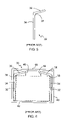
In order to protect the contents from vertical forces and shocks, a polymer foam cushion may be employed at the top or the bottom of the container. The cellular structure shown in FIGS. 1–2 has a recessed rectangular area that is adapted to receive a rectangular polymer foam cushion, such as the one shown in FIG. 3. FIG. 4 shows, in cross-section, the container and cellular structure of FIGS. 1–2 which additionally includes the polymer foam cushion of FIG. 3. Polymer foam, however, is expensive. In addition, recycling polymer foam is complicated and recycling facilities are not always available. Further, containers that employ polymer foam cushions may be difficult to assemble.
FIGS. 5–6 show another method for protecting the contents of a container from vertical forces and shocks. FIG. 5 shows an exemplary folded corrugated board that may be employed inside a container. FIG. 6 shows a cross-sectional view of a container having a pair of folded corrugated boards. The dashed line represents one or more articles in the container. Each folded corrugated board includes a vertical section parallel to a container wall that remains stationary, an end section that projects over the article at an angle above the horizontal, and a fold or score at the junction of the two sections. When the lid experiences a vertical force or shock, the end section bends inward about the fold providing cushioning. As the shown folded corrugated board bends down, however, the end section can contact the articles in the container. This can result in the force or shock being transferred directly to the articles. Moreover, containers that employ folded corrugated board may be difficult to assemble.
Accordingly, there is a need for shock absorbing container in which articles packaged within the container are protected from vertical forces and shocks.
BRIEF SUMMARY OF THE INVENTION
Disclosed herein is a shock absorbing container. Within the scope of the invention is a shock absorbing container assembly for packaging one or more articles, including an outer container, a sheet member, and an article container. The outer container has a closed configuration for shipping the articles. In the closed configuration, the outer container includes an inner top surface and an opposed inner bottom surface that are substantially fixedly spaced apart in a vertical axis. The sheet member has a bottom surface and at least one preformed foldable portion. The preformed foldable portion is folded away from the bottom surface of the sheet member and terminates at a free distal edge. The free distal edge bears against the top surface of the outer container when receiving vertically directed forces transmitted by the top surface. The article container is disposed inside the outer container and is for receiving articles. The article container includes a plurality of intersecting walls so that, when receiving vertically directed forces transmitted by the sheet member at least two of the walls have upper ends bearing against the bottom surface of the sheet member and lower ends bearing against the bottom surface of the outer container. The walls, by intersecting with each other, support one another to maintain the walls upright so that the walls are enabled to support the vertically directed forces transmitted by the sheet member.
In one preferred embodiment, the sheet member is formed of corrugated paperboard.
The foregoing and other objectives, features, and advantages of the invention will be more readily understood upon consideration of the following detailed description of the invention, taken in conjunction with the accompanying drawings.
BRIEF DESCRIPTION OF THE SEVERAL VIEWS OF THE DRAWINGS
FIG. 1 illustrates a prior art cellular structure.
FIG. 2 illustrates the cellular structure of FIG. 1 within a container.
FIG. 3 illustrates a prior art polymer foam cushion.
FIG. 4 is a cross-sectional view the polymer foam cushion of FIG. 3 disposed within the cellular structure and container of FIG. 2.
FIG. 5 illustrates a prior art folded corrugated board.
FIG. 6 is a cross-sectional view of a pair of the folded corrugated boards of FIG. 5 disposed within a container.
FIG. 7 illustrates a shock absorbing container assembly that includes an outer container and an article container having notched and reverse notched partitions according to the present invention.
FIG. 8 illustrates the article container of FIG. 7.
FIG. 9 shows a reverse notched partition of the article container of FIG. 8
FIG. 10 shows a notched partition of the article container of FIG. 8.
FIG. 11 illustrates an alternative preferred embodiment of an outer container.
FIG. 12 illustrates a sheet member according to the present invention.
FIG. 13 illustrates the sheet member of FIG. 12 in a folded arrangement.
FIG. 14 illustrates an alternate embodiment of a sheet member according to the present invention.
FIG. 15 illustrates the sheet member of FIG. 14 in a folded arrangement.
FIG. 16 illustrates two of the sheet members of FIG. 12 disposed within an article container according to the present invention.
FIG. 17 is a cross-sectional view of the sheet members and article holding container of FIG. 16.
DETAILED DESCRIPTION OF A PREFERRED EMBODIMENT
This detailed description of a preferred embodiment is organized as follows: First, the exemplary prior art packaging methods shown in FIGS. 1–6 are described in detail. Second, the present invention is discussed with reference to FIGS. 7–17. Finally, the meaning of some of the terms and phrases used herein are discussed.
FIG. 1 illustrates an exemplary cellular structure 20. FIG. 2 shows the cellular structure 20 of FIG. 1 within a container 22. A number of articles may be placed in the shown cellular structure 20; typically, one article per inner cell 24. Generally, articles are not placed in the outer cells 26. The cellular structure 20 does not provide protection from vertical forces or shocks.
FIG. 3 illustrates a polymer foam cushion 28 that may be employed at the top or the bottom of a container to protect the contents from vertical forces and shocks. The cellular structure shown in FIGS. 1–2 has a recessed rectangular area 30 that is adapted to receive the polymer foam cushion 28. Polymer foam is expensive and can be difficult to recycle.
FIG. 4 shows, in cross-section, the cellular structure 20, the container 22, and the polymer foam cushion 28 disposed in recessed area 30.
FIG. 5 illustrates an exemplary folded corrugated board 32 that may be employed inside a container 40. The folded corrugated board 32 includes a vertical section 34, an end section 36, and a fold 38 at the junction of the two sections.
FIG. 6 shows a cross-sectional view of a container 40 having a pair of folded corrugated boards 32. The dashed line represents an article 42 within the container. The vertical sections 34 of each folded corrugated board 32 are parallel to the side walls of the container 40. The end section 36 projects over the article 42 at an angle above the horizontal. When the top side 46 receives a vertical force or shock, the end section 36 bends down about the fold 38 in the direction of arrows 48. When the end section 36 bends down, it can contact the article 42. If end section 36 does contact the article 42, the vertical force or shock will be transferred to the article 42.
Turning now to FIGS. 7–16, preferred embodiments of a shock absorbing container assembly according to the present invention are illustrated. The present invention provides protection from vertical forces and shocks without relying on polymer foam. Moreover, vertical forces or shocks are not transferred to the article. The shock absorbing container assembly includes three components: an outer container, a sheet member, and an article container.
FIG. 7 illustrates a preferred embodiment of a shock absorbing container assembly 50 that includes one preferred embodiment of an outer container 52 having four side walls 54, a bottom side 56, and a lid 58. The side walls 54 define a vertical (“y”) axis. The outer container 52 also includes an inner bottom surface 62 (not shown). The inner bottom surface 62 is opposite bottom side 56. The shown lid 58 is removable. Alternatively, the lid 58 may be hingedly attached to the outer container 52. As such, the shock absorbing container assembly 50 has two configurations: a closed configuration when the lid 58 is disposed as a top side of the outer container 52 and an open configuration when the lid 58 is not so disposed. In the closed configuration, the outer container 52 additionally includes an inner top surface 60. The inner top surface 60 is opposite a top side 64 of the lid 58. The inner top surface 60 and the inner bottom surface 62 are substantially fixedly spaced apart in the vertical axis by a distance defined by the height of the side walls 54. One preferred embodiment of an article container 66 is disposed within the outer container 52.
FIG. 8 illustrates the article container 66. The article container 66 has a plurality of intersecting walls. The intersection of one wall with another maintains both walls in an upright position. Each wall provides support to the other by means of the coupling provided by the intersection. For example, if a vertical force or shock is exerted on an upper end of a wall, the wall will maintain its upright position through the support provided by the intersection. Of course, there is a limit to the amount of support that can be provided and normally the intersection of two corrugated board walls will not prevent crushing should a sufficient vertical force be applied.
The shown article container 66 is assembled from two types of partitions that are shown in FIGS. 9–10. FIG. 9 shows a reverse notched partition 68. FIG. 10 shows a notched partition 70. Generally, an article container 66 includes two or more parallel reverse notched partitions 68 and at least two parallel notched partitions 70. Notches 72 in the reverse notched partition 68 are received in appropriate notches 74 of the notched partition 70. When assembled, the reverse notched and notched partitions 68, 70 are at right angles to each other. There is generally one more reverse notched partition 68 than the total number of articles. Referring to FIG. 8, articles are placed in cells 74, but not in the outer cells 76 as these cells are intended to protect the articles from horizontal forces or shocks (along the x and z axis).
Other embodiments for forming the plurality of intersecting walls of the article container 66 are contemplated. In an alternative embodiment, a single sheet of material may be folded to form two or more intersecting walls. In yet another embodiment, the partitions can be formed by the use of adhesive material, such as glue. Moreover, the intersecting walls can be made from a plurality of parts or cut-outs.
The article container 66 also includes a sheet member holding recess 78 that is formed from a plurality of reverse notched partitions 68. Referring to FIG. 9, the sheet member holding recess 78 on each reverse notched partitions 68 has an upper end 80 and a pair of inclined edges 82. An acute angle 84 defines the relation between the upper end 80 and the inclined edge 82.
FIG. 11 illustrates an alternative preferred embodiment of an outer container 52 shown in cut-away. The outer container 52 includes an inner top surface 60, an inner bottom surface 62, and side walls 54 that define a vertical (“y”) axis. The inner top surface 60 and the inner bottom surface 62 are substantially fixedly spaced apart in the vertical axis as defined by the height of the side walls 54. The outer container 52 may have an open and closed configuration that is provided by a side wall 54 that is removable.
FIGS. 12–13 illustrate two views of a sheet member 86. In FIG. 12, the sheet member 86 is in the form of a corrugated board blank having two fold lines 88. The fold lines 88 define a bottom surface 90 and two preformed foldable portions 92. The fold lines 88 may be lines on or scores in the corrugated board blank. Additionally, each preformed foldable portion 92 has a free distal edge 94. FIG. 13 illustrates the sheet member 86 in an arrangement in which each preformed foldable portion 92 has been folded upward along its respective adjacent fold line 88. As shown, each preformed foldable portions 92 projects away from the bottom surface 90 at an angle 96 of approximately 30 degrees. The shown angle 96 is exemplary and any angle between 1 and 89 degrees is contemplated.
The fold lines 88 are preferably provided at the location shown in FIGS. 12, 13. However, the fold lines 88 may be closer to or farther away from the free distal edge 94. The location of the fold line 88 is defined by the length “1” of the preformed foldable portion 92. In addition, while it is essential that the sheet member have at least one pre-folded portion, it is preferable that the sheet member have at least two pre-folded portions.
FIGS. 14, 15 illustrate a sheet member 98 having an alternative embodiment of the preformed foldable portion 100. In the shown embodiment, the preformed foldable portion 100 is defined within the sheet member 98. In FIG. 14, the sheet member 98 has three cut lines 102 that are cut into it and a transverse fold line 104. The material is separated along the cut lines 102 and folded about the fold line 104 to create a preformed foldable portion 100, as shown in FIG. 15.
FIG. 16 illustrates the sheet member 86 disposed within the sheet member holding recess 78 of an article container 66. The sheet member holding recess 78 captures the sheet member 86 thereby preventing side-to-side movement of the sheet member with respect to the article container 66. Referring to FIGS. 9 and 16, the sheet member holding recess 78 is preferably provided with an upper end 80, inclined edges 82, and acute angles 84 that define the relation between the upper end 80 and the inclined edges 82. The inclined edges 82 confine the preformed foldable portions 92 with respect to vertical movement. The bottom surface 90 of the sheet member 86 contacts the upper end 80 of the reverse notched partition 68. The article container 66 also has a plurality of lower ends that contact the bottom surface of the outer container 52 when the article container 66 is positioned within the outer container 52.
The article container 66 has an optional second sheet member 86 disposed within a lower sheet member holding recess 108. When the article container 66 is positioned within the outer container 52, the second sheet member holding recess 108 and the second sheet member 86 will be disposed adjacent to the inner bottom surface 58 of the outer container 52. This optional configuration protects against vertical forces and shocks from below the shock absorbing container assembly 50.
FIG. 17 shows, in cross-section, the article holding container 66 together with the two of the sheet members 86 of FIG. 16 disposed in an outer container 54.
When the article container 66 is disposed in the outer container 52 the free distal edges 94 may be in direct contact or close proximity to the inner top surface 60. When the outer container experiences a vertical force or shock, the inner top surface 60 contacts the free distal edges 94 and the preformed foldable portions 92 bend inward about fold line 88 providing cushioning. The preformed foldable portion 92 and the fold line 88 together effectively act as a spring. The strength of the spring is proportional to the length “l” of the preformed foldable portion 92.
The intended meaning of some of the terms and phrases used herein is discussed below.
The phrase “sheet member” 86, 98 refers to both the flat blank arrangements shown in FIGS. 12, 14 and the folded arrangements shown in FIGS. 13, 15. The sheet member can be shipped and stored in the flat blank arrangement for later assembly into the folded arrangement when needed. While the shown sheet member 86 is preferably made of corrugated board, it may be made from plastics, composites, or other materials.
The phrase “article holding container” refers to both the partitions shown in FIGS. 9–10 and the assembled article containers, such as those shown in FIGS. 8 and 16. The article holding container can be shipped and stored as unassembled partitions for later assembly into the article containers of FIGS. 8 and 16 when needed.
The phrase “free distal end” 94, with reference to the termination point of the pre-folded portion of the sheet member, means that the free distal end has enough freedom of movement to provide shock absorption. Complete freedom of movement of the pre-folded portion is not required. Any range of motion sufficient that allows the free distal end 94 to move in response to a shock is sufficient.
The word “vertical” is used herein only to provide a frame of reference for describing the invention. It will be appreciated that the invention can be easily adapted to provide shock absorption against a force or shock originating in any direction. For example, an article container with a sheet member holding recess (and a sheet member disposed therein) in a side wall will provide shock absorption in the horizontal direction.
The word “shipping,” with reference to the outer container 52 in a closed configuration, refers to any situation in which the container assembly may be subjected to forces or shocks.
The phrase “fixedly spaced apart,” with reference to the inner top surface and the inner bottom surface of the outer container, means that the top and bottom surfaces are spaced apart by a defined distance that does not vary in a substantial way under normal conditions. The phrase is not intended to contemplate that the surfaces are spaced apart by a precisely defined distance at all times. For example, a vertical force exerted downward on the lid 58 may cause it to bend. Similarly, a vertical force exerted downward on the lid 58 may result in a deformation, e.g., a dent. It is contemplated that an inner top or bottom surface may bend or be deformed and still be “fixedly spaced apart” from each other as this phrase is used herein.
The terms and expressions that have been employed in the foregoing specification are used as terms of description and not of limitation, and are not intended to exclude equivalents of the features shown and described or portions of them. The scope of the invention is defined and limited only by the claims that follow.

Claims (12)

1. A shock absorbing container assembly for packaging one or more articles, comprising:
an outer container;
an inner container defining at least one cellular compartment for disposition inside said outer container, said compartment for receiving at least one of the articles and said outer container for completing an enclosure therefor; and
a sheet member for disposition between said inner and outer containers, said sheet member comprising a substantially flat bottom portion for bearing on said inner container over a flat face of said bottom portion and a first, substantially flat foldable portion foldably connected to said bottom portion along a first linear line for folding away from said bottom portion and bearing on said outer container along a free distal edge of said first foldable portion;
wherein said free distal edge is substantially linear;
wherein said sheet member includes a second, substantially flat foldable portion hingedly connected to said bottom portion along a second linear line for folding away from said bottom portion and bearing on said outer container along a free distal edge of said second foldable portion, said first and second lines being substantially parallel;
wherein said inner container includes a plurality of said compartments for receiving a corresponding plurality of the articles;
wherein said inner container comprises a plurality of slotted, intersecting walls defining said compartments and at least two of said walls include cut-outs adapted for receiving said sheet member; and
wherein each of said at least two walls includes two opposed, mirror-image cut-outs sharing a single first linear edge and having respective second linear edges defining respective acute angles with respect to said first linear edge.
2. The container assembly of claim 1, wherein said sheet member is formed of corrugated paperboard.
3. The container assembly of claim 2, wherein said walls are formed of corrugated paperboard.
4. The container assembly of claim 3, wherein said outer container is formed of corrugated paperboard.
5. A shock absorbing container assembly for packaging one or more articles, comprising:
an outer container;
an inner container defining at least one cellular compartment for disposition inside said outer container, said compartment for receiving at least one of the articles and said outer container for completing an enclosure therefor; and
a sheet member for disposition between said inner and outer containers, said sheet member comprising a substantially flat bottom portion for bearing on said inner container over a flat face of said bottom portion and a first, substantially flat foldable portion foldably connected to said bottom portion along a first linear line for folding away from said bottom portion and bearing on said outer container along a free distal edge of said first foldable portion;
wherein said free distal edge is substantially linear;
wherein said inner container includes a plurality of said compartments for receiving a corresponding plurality of the articles;
wherein said inner container comprises a plurality of slotted, intersecting walls defining said compartments and at least two of said walls include cut-outs adapted for receiving said sheet member; and
wherein each of said at least two walls includes two opposed, mirror-image cut-outs sharing a single first linear edge and having respective second linear edges defining respective acute angles with respect to said first linear edge.
6. The container assembly of claim 5, wherein said sheet member is formed of corrugated paperboard.
7. The container assembly linear of claim 6, wherein said walls are formed of corrugated paperboard.
8. The container assembly linear of claim 7, wherein said outer container is formed of corrugated paperboard.
9. A shock absorbing container assembly for packaging one or more articles, comprising:
an outer container;
an inner container defining at least one cellular compartment for disposition inside said outer container, said compartment for receiving at least one of the articles and said outer container for completing an enclosure therefor; and
a sheet member for disposition between said inner and outer containers, said sheet member comprising a substantially flat bottom portion for bearing on said inner container over a flat face of said bottom portion and a first, substantially flat foldable portion foldably connected to said bottom portion along a first linear line for folding away from said bottom portion and bearing on said outer container along a free distal edge of said first foldable portion;
wherein said inner container comprises plurality of slotted, intersecting walls defining said compartments and at least two of said walls include cut-outs adapted for receiving said sheet member; and
wherein each of said at least two walls includes two opposed, mirror-image cut-outs sharing a single first linear edge and having respective second linear edges defining respective acute angles with respect to said first linear edge.
10. The container assembly of claim 9, wherein said sheet member is formed of corrugated paperboard.
11. The container assembly of claim 10, wherein said walls are formed of corrugated paperboard.
12. The container assembly of claim 11, wherein said outer container is formed of corrugated paperboard.
US10/320,010 2002-12-16 2002-12-16 Shock absorbing container Expired - Fee Related US6964339B2 (en)

Priority Applications (1)

Application Number Priority Date Filing Date Title
US10/320,010 US6964339B2 (en) 2002-12-16 2002-12-16 Shock absorbing container

Applications Claiming Priority (1)

Application Number Priority Date Filing Date Title
US10/320,010 US6964339B2 (en) 2002-12-16 2002-12-16 Shock absorbing container

Publications (2)

Publication Number Publication Date
US20040112788A1 US20040112788A1 (en) 2004-06-17
US6964339B2 true US6964339B2 (en) 2005-11-15

Family

ID=32506770

Family Applications (1)

Application Number Title Priority Date Filing Date
US10/320,010 Expired - Fee Related US6964339B2 (en) 2002-12-16 2002-12-16 Shock absorbing container

Country Status (1)

Country Link
US (1) US6964339B2 (en)

Cited By (3)

* Cited by examiner, † Cited by third party
Publication number Priority date Publication date Assignee Title
US20050103673A1 (en) * 2002-04-04 2005-05-19 Reinhard Eichenberger Device for receiving a commodity in a fixed position
US20080197032A1 (en) * 2007-02-21 2008-08-21 Quantum Corporation Protective cartridge case having zero-tension latch
US20080197036A1 (en) * 2007-02-21 2008-08-21 Quantum Corporation Protective cartridge case having shock absorbing features

Families Citing this family (1)

* Cited by examiner, † Cited by third party
Publication number Priority date Publication date Assignee Title
JP2024025977A (en) * 2022-08-15 2024-02-28 富士フイルム株式会社 packaging

Citations (21)

* Cited by examiner, † Cited by third party
Publication number Priority date Publication date Assignee Title
US987958A (en) * 1909-04-23 1911-03-28 Sefton Mfg Company Packing or shipping box.
US2377604A (en) * 1944-06-01 1945-06-05 Nat Union Radio Corp Carton
US2742219A (en) * 1953-10-15 1956-04-17 Lloyd D Van Antwerpen Accordion pleated cushioning strip
US2979248A (en) 1959-10-15 1961-04-11 Washington Box Ltd Packaging of fragile articles
US3144188A (en) 1962-08-22 1964-08-11 Waldorf Paper Prod Co Reinforcing pad for container liner
US4247289A (en) 1979-11-02 1981-01-27 Mccabe James E Paper spring method
US4293070A (en) 1979-03-30 1981-10-06 Ohlbach Ralph C For protecting printed circuit boards and other items against the ravages of a discharge of static electricity
US4363579A (en) 1980-02-25 1982-12-14 Rogers Eugene A Damage prevention void filler for separating loads during transit
US4594492A (en) * 1984-06-04 1986-06-10 James River Corporation Microwave package including a resiliently biased browning layer
US4865200A (en) 1989-01-13 1989-09-12 Sullivan Gordon R Shipping container for fragile items
US4954385A (en) 1987-10-19 1990-09-04 Haarkosmetik and Parfumerien Carton pad
US5045330A (en) * 1989-08-23 1991-09-03 James River Corporation Biased food contact container and container insert
US5088601A (en) 1991-08-05 1992-02-18 At&T Bell Laboratories Circuit board shipping carton
US5121838A (en) 1991-10-23 1992-06-16 Intepac Technologies Inc. Package having product clamping for card-like products
US5223121A (en) 1991-05-02 1993-06-29 Dickie Robert G Protective carton with progressive product clamping
US5303820A (en) 1992-06-12 1994-04-19 Claude Comtois Packaging for protecting printed circuit board and other products
US5484241A (en) 1994-12-22 1996-01-16 Shippers Paper Products Company Collapsible void filler
US5484519A (en) 1992-07-14 1996-01-16 Randa Corp. Method and apparatus for transporting and displaying neckties
US5529187A (en) 1994-12-09 1996-06-25 The Mead Corporation Multi-circuit board carton and blank
US5613610A (en) 1988-05-04 1997-03-25 Bradford Company Naturally degradable and recyclable static-dissipative packaging material
US5823352A (en) 1997-06-03 1998-10-20 Summit Container Corporation Container with shock-absorbing insert

Patent Citations (21)

* Cited by examiner, † Cited by third party
Publication number Priority date Publication date Assignee Title
US987958A (en) * 1909-04-23 1911-03-28 Sefton Mfg Company Packing or shipping box.
US2377604A (en) * 1944-06-01 1945-06-05 Nat Union Radio Corp Carton
US2742219A (en) * 1953-10-15 1956-04-17 Lloyd D Van Antwerpen Accordion pleated cushioning strip
US2979248A (en) 1959-10-15 1961-04-11 Washington Box Ltd Packaging of fragile articles
US3144188A (en) 1962-08-22 1964-08-11 Waldorf Paper Prod Co Reinforcing pad for container liner
US4293070A (en) 1979-03-30 1981-10-06 Ohlbach Ralph C For protecting printed circuit boards and other items against the ravages of a discharge of static electricity
US4247289A (en) 1979-11-02 1981-01-27 Mccabe James E Paper spring method
US4363579A (en) 1980-02-25 1982-12-14 Rogers Eugene A Damage prevention void filler for separating loads during transit
US4594492A (en) * 1984-06-04 1986-06-10 James River Corporation Microwave package including a resiliently biased browning layer
US4954385A (en) 1987-10-19 1990-09-04 Haarkosmetik and Parfumerien Carton pad
US5613610A (en) 1988-05-04 1997-03-25 Bradford Company Naturally degradable and recyclable static-dissipative packaging material
US4865200A (en) 1989-01-13 1989-09-12 Sullivan Gordon R Shipping container for fragile items
US5045330A (en) * 1989-08-23 1991-09-03 James River Corporation Biased food contact container and container insert
US5223121A (en) 1991-05-02 1993-06-29 Dickie Robert G Protective carton with progressive product clamping
US5088601A (en) 1991-08-05 1992-02-18 At&T Bell Laboratories Circuit board shipping carton
US5121838A (en) 1991-10-23 1992-06-16 Intepac Technologies Inc. Package having product clamping for card-like products
US5303820A (en) 1992-06-12 1994-04-19 Claude Comtois Packaging for protecting printed circuit board and other products
US5484519A (en) 1992-07-14 1996-01-16 Randa Corp. Method and apparatus for transporting and displaying neckties
US5529187A (en) 1994-12-09 1996-06-25 The Mead Corporation Multi-circuit board carton and blank
US5484241A (en) 1994-12-22 1996-01-16 Shippers Paper Products Company Collapsible void filler
US5823352A (en) 1997-06-03 1998-10-20 Summit Container Corporation Container with shock-absorbing insert

Cited By (4)

* Cited by examiner, † Cited by third party
Publication number Priority date Publication date Assignee Title
US20050103673A1 (en) * 2002-04-04 2005-05-19 Reinhard Eichenberger Device for receiving a commodity in a fixed position
US7658281B2 (en) * 2002-04-04 2010-02-09 Swatch Ag Device for receiving a commodity in a fixed position
US20080197032A1 (en) * 2007-02-21 2008-08-21 Quantum Corporation Protective cartridge case having zero-tension latch
US20080197036A1 (en) * 2007-02-21 2008-08-21 Quantum Corporation Protective cartridge case having shock absorbing features

Also Published As

Publication number Publication date
US20040112788A1 (en) 2004-06-17

Similar Documents

Publication Publication Date Title
US6840381B2 (en) Packaging for fragile items
US5730289A (en) Box and insert for shipping glass bottles
US7281648B2 (en) Tray with means for holding a vertical post
US8474686B2 (en) Corrugated container
US6675970B1 (en) Cushioning support member and fabricating method thereof
US20060102515A1 (en) Suspension packaging system
US8875889B2 (en) Packaging cushion structure made from stiff paper-board sheets
WO1999003741A1 (en) Double panel boxes
US6685026B1 (en) One-piece container with integral internal cushioning supports
US6964339B2 (en) Shock absorbing container
US5002188A (en) Collapsible protective carton with interior cradle
US7258235B2 (en) Fiberboard carton with secured die cut insert
US20070251985A1 (en) Blank and an open-top carton constructed therefrom
US3923235A (en) Protective carton
US5242107A (en) Paperboard packages for fragile articles
CN101670908A (en) Honeycomb structure package
KR200391925Y1 (en) Cushion for a packaging box
KR200404101Y1 (en) Cushion for a packaging box
CN219770650U (en) Fruit packing box
JPH11268768A (en) Packaging body with cushioning function
US20230356909A1 (en) Retention packaging system
JP3212265U (en) Packaging box and its packaging structure
KR20240001903A (en) Interior member and packaging box having the same
JP2009298448A (en) Partition and packing box with partition
KR20070119038A (en) Packaging box

Legal Events

Date Code Title Description
AS Assignment

Owner name: EPSON PORTLAND, INC., OREGON

Free format text: ASSIGNMENT OF ASSIGNORS INTEREST;ASSIGNOR:MEYER, JOHN S.;REEL/FRAME:013592/0936

Effective date: 20021204

AS Assignment

Owner name: SEIKO EPSON CORPORATION, JAPAN

Free format text: ASSIGNMENT OF ASSIGNORS INTEREST;ASSIGNOR:EPSON PORTLAND, INC.;REEL/FRAME:014081/0409

Effective date: 20030512

FEPP Fee payment procedure

Free format text: PAYOR NUMBER ASSIGNED (ORIGINAL EVENT CODE: ASPN); ENTITY STATUS OF PATENT OWNER: LARGE ENTITY

FPAY Fee payment

Year of fee payment: 4

FPAY Fee payment

Year of fee payment: 8

REMI Maintenance fee reminder mailed
LAPS Lapse for failure to pay maintenance fees

Free format text: PATENT EXPIRED FOR FAILURE TO PAY MAINTENANCE FEES (ORIGINAL EVENT CODE: EXP.)

STCH Information on status: patent discontinuation

Free format text: PATENT EXPIRED DUE TO NONPAYMENT OF MAINTENANCE FEES UNDER 37 CFR 1.362

FP Lapsed due to failure to pay maintenance fee

Effective date: 20171115