US6963621B1 - Method and apparatus for reducing distortion of digital data - Google Patents
Method and apparatus for reducing distortion of digital data Download PDFInfo
- Publication number
- US6963621B1 US6963621B1 US09/807,857 US80785701A US6963621B1 US 6963621 B1 US6963621 B1 US 6963621B1 US 80785701 A US80785701 A US 80785701A US 6963621 B1 US6963621 B1 US 6963621B1
- Authority
- US
- United States
- Prior art keywords
- signal
- link
- distortion
- approximation
- stages
- Prior art date
- Legal status (The legal status is an assumption and is not a legal conclusion. Google has not performed a legal analysis and makes no representation as to the accuracy of the status listed.)
- Expired - Lifetime
Links
Images


Classifications
-
- H—ELECTRICITY
- H03—ELECTRONIC CIRCUITRY
- H03F—AMPLIFIERS
- H03F1/00—Details of amplifiers with only discharge tubes, only semiconductor devices or only unspecified devices as amplifying elements
- H03F1/32—Modifications of amplifiers to reduce non-linear distortion
- H03F1/3241—Modifications of amplifiers to reduce non-linear distortion using predistortion circuits
-
- H—ELECTRICITY
- H04—ELECTRIC COMMUNICATION TECHNIQUE
- H04L—TRANSMISSION OF DIGITAL INFORMATION, e.g. TELEGRAPHIC COMMUNICATION
- H04L27/00—Modulated-carrier systems
- H04L27/32—Carrier systems characterised by combinations of two or more of the types covered by groups H04L27/02, H04L27/10, H04L27/18 or H04L27/26
- H04L27/34—Amplitude- and phase-modulated carrier systems, e.g. quadrature-amplitude modulated carrier systems
- H04L27/36—Modulator circuits; Transmitter circuits
- H04L27/366—Arrangements for compensating undesirable properties of the transmission path between the modulator and the demodulator
- H04L27/367—Arrangements for compensating undesirable properties of the transmission path between the modulator and the demodulator using predistortion
- H04L27/368—Arrangements for compensating undesirable properties of the transmission path between the modulator and the demodulator using predistortion adaptive predistortion
Definitions
- This invention relates to the transmission of digital data, and in particular to method and apparatus for reduction of distortion incurred by representations of digital data during passage through transmission links.
- Transmission of a modulated signal through transmission links result in distortion of the signal.
- This distortion is due, in part at least, to the non-linear effects of passage of a signal through the transmission link.
- Distortion leads to a change in location of the constellation points of any given modulation scheme.
- An increase in the order of modulation results in a decrease in the distance between constellation points, and so leads to a higher probability of distortion leading to errors occurring during the demodulation of higher order modulation schemes.
- Prior art methods used to reduce the effects of distortion by non-linear component(s) within transmission links include use of at least partially compensating pre-correction.
- One approach is that of feed-forward, where the non-linear output of an amplifier is sampled, and compared with the required signal prior to transmission, with the resultant error being subtracted from the amplifier output.
- This approach is only suitable for systems in which the pre-distorter and amplifier are co-located.
- this technique is used for satellite transmission links the opportunity for introduction or modification of the pre-distorter to take account of changes in amplifier characteristics is severely limited.
- constellation pre-distortion where the constellation points generated by the modulator are pre-distorted such that at the amplifier output the constellation points are located in their correct relative positions.
- This method is suitable only for transmission links that are memory-less. This precludes the use of this approach where pulse shaping takes place before non-linear amplification of the signal. Therefore, it is not suitable for those transmission links that include bandpass filtering of the signal.
- Signal pre-distortion performed at the radio (RF), intermediate (IF) or base band frequencies is often carried out by application of an inverse function of the distortion to the signal as disclosed in WO-A-95132561 and U.S. Pat. No. 4,992,754.
- This type of pre-correction generates out of band components, which are then carried through to the amplifier input.
- the amplifier has an input filter, as is common for amplifiers used in satellite transmission links, then these components may be removed from the signal which becomes the input to the amplifier.
- the distortion imposed by the amplifier will not be accurately corrected as the amplifier input signal is not the entire transmitted signal.
- this form of pre-correction is not effective for correction of amplifiers contained within satellite transponders where the bandwidth of the incoming signal is high in relation to the bandwidth of the transponder. Additionally, for digital transmission using higher order modulation schemes, this type of pre-correction requires very high clocking rates in order to generate the wide-band pre-distortion components.
- a method of pre-distorting a signal of a satellite transmission link said signal being modulated to carry symbols representative of digital data, so as to offset later distortion of the signal during transmission across the satellite transmission link, said link having root Nyquist bandpass filters in respective up and down links, the method including passing the signal through a cascade of identical pre-distorting states, each of which generates an approximation of the required pre-distortion, each successive stage receiving the approximation from the preceding stage so that errors in successive approximations converge toward zero with increase in the number of stages.
- a satellite transmission link including root Nyquist bandpass filters in respective up and down links and apparatus for pre-distortion of a signal, modulated to carry symbols representing digital data, so as to offset later distortion of the signal during transmission across said link
- the apparatus comprising a cascade of identical pre-distorting stages, each said stage having means for generating an approximation of the required pre-distortion, and each successive stage being connected to receive the approximation from the preceding stage so that the errors in successive approximations converge toward zero with increase in the number of stages.
- the method and apparatus of this invention allows input of a complex signal at a rate as low a one sample per symbol to the pre-distorter, and generating at its output a complex signal which may be at the same rate. This means that implementation of the hardware is practical for systems operating at higher symbol rates.
- the method and apparatus of the invention are particularly suited to pre-distortion of a modulated signal which is subsequently transmitted through a satellite transmission link as it provides a ground based means of applying pre-distortion of the amplifier located on the satellite.
- transmission links can include band pass filters between the means of modulating the signal and the amplifier. As is described above, such filters are known to remove at least substantial portions of any out of band components contained within a signal. Additionally, this invention provides accurate pre-distortion for transmission links having one of more band pass filter regardless of the location of such filter(s). Satellite transmission links commonly employ ground and satellite-based band pass filters.
- the method and apparatus of this invention allows accurate pre-distortion for a transmission link carrying any constellation pattern and having any non-linear amplifier, irrespective of whether the link is memory less or not.
- pre-distortion to be applied to a signal for subsequent transmission through a transmission link having a band pass filter at each of the transmitter and receiver ends of the link. Additionally, by taking past and future symbols of the signal into account, not only can the static position of the constellation points to be pre-distorted accurately to take account of the effects of passage through the non-linearity of the link, but also the effects of inter-symbol interference (i.e. smearing) are substantially reduced.
- FIG. 1 is a schematic diagram of a satellite transmission system incorporating a satellite transmission link.
- FIG. 2 is a schematic diagram of a pre-distorter of the present invention.
- FIG. 3 is a schematic diagram of the distorting function FM 1 of FIG. 2 .
- FIG. 4 is a representation of an ideal 16 QAM constellation prior to transmission through a transmission link.
- FIG. 5 is a representation of the output from a receiving Nyquist filter corresponding to the transmission link input of FIG. 4 .
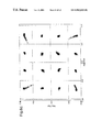
- FIGS. 6 a to 6 d show computer simulations of outputs from a receiving Nyquist filter when different numbers of successive approximation stages are used.
- FIG. 7 is a graphical comparison of Bit Error Rates of differing pre-distortion circumstances.
- FIGS. 8 a and 8 b show the output of a receiver Nyquist filter for 32 QAM using a pre-distorter of the invention, and the corresponding constellation at the input to a transmitter Nyquist filter respectively.
- FIG. 9 shows a computer simulation of the output spectrum of the pre-distorter in comparing it with the spectrum without the use of pre-distortion.
- FIG. 10 is a schematic diagram of a feedback control loop.
- FIG. 1 there is shown a satellite transmission link 1 , having a root Nyquist band-pass filter 2 , IQ modulator 3 and up-converter 4 prior to a transmitter 5 .
- the transmitter provides an uplink to a satellite 6 , which in turn provides a downlink to a number of receivers, one of which is shown as receiver 7 .
- the receiver end of the satellite transmission link 1 can be seen as a reverse of the transmission end, with the receiver 7 connected successively through a down-converter 8 , an IQ demodulator 9 and a root Nyquist band-pass filter 10 .
- an input base band frequency signal being one which has been modulated by a particular technique and scheme such as 16 QAM and having I and Q complex components, is filtered by the root Nyquist band-pass filter 2 .
- Nyquist filtering it is usual to use Nyquist filtering within transmission links in order to constrain the bandwidth of the transmitted signal.
- Nyquist filtering of the signal is conducted by root Nyquist filters placed at each of the transmitter and receiver ends of the transmission link. Nyquist and root Nyquist filters impose a linear distortion upon the modulated signal.
- Each of the I and Q components of the root Nyquist filtered signal are provided as inputs to the IQ modulator 3 such that the input to up-converter 4 is a modulated carrier which represents the digital data of the chosen modulation scheme.
- the up-converter changes the frequency of the input signal to a higher frequency than base band.
- the higher frequency signal is transmitted to satellite 6 , where it is received by the satellite's transponder (not shown), amplified by a travelling wave tube amplifier (TWT) and retransmitted from the transponder to a plurality of receivers 7 .
- the transponder is often constructed such as to ensure that the transponder input is passed through band-pass filters before and after being amplified by the TWT.
- Band-pass filters include the characteristics of not allowing out of band components to pass through the filter.
- the signal On receipt of the transponder output by receiver 7 the signal is processed by each of down-converter 8 , IQ demodulator 9 and root Nyquist filter 10 to provide an output from the transmission link 1 in the form of a base band frequency signal having I and Q components. This output is then subsequently demodulated to obtain the digital data transmitted by the symbols within the modulation scheme.
- FIG. 1 also shows a pre-distorter 12 located prior to the transmission link 1 .
- the pre-distorter is adapted to operate in accordance with the invention of this application, and arranged to apply pre-distortion to an incoming signal to compensate for the distortion subsequently applied to that signal during its passage through the satellite transmission link 1 .
- FIG. 2 is a block diagram of the pre-distorter 12 in greater detail. It is assumed that all signals (input to, output from and within the pre-distorter) are complex signals. However, it will be understood by those skilled in the art that in a practical implementation these signal could be in the form of either Cartesian or polar representation.
- the output of summing node 23 is scaled by a value A by a multiplier 24 .
- This output 26 is determined by equation (1) given below.
- Output 26 (input 19 )* A ⁇ (output 22 )* A +(input 19 )
- pre-distorter 12 may additionally include an initial approximator 28 .
- This initial approximator is arranged to operate function IM 1 , which is a function arranged to provide an output which is approximately the inverse of forward model distorting function FM 1 as implemented by forward model distorting functions 21 , 27 and their equivalents in further successive stages.
- function IM 1 is a function arranged to provide an output which is approximately the inverse of forward model distorting function FM 1 as implemented by forward model distorting functions 21 , 27 and their equivalents in further successive stages.
- the initial approximator 28 may be a function which places the constellation points in the correct place for pre-distortion but which does not dynamically change their position from symbol to symbol. This is known as a static pre-distortion.
- a static pre-distortion for a rough approximation substantially reduces the number of successive approximation stages required.
- one static correction stage plus three dynamic stages is sufficient to attain the desired pre-distortion of a satellite transmission link such as that of FIG. 1 .
- the distorting function 21 for the transmission link 1 of FIG. 1 may be of the form shown in FIG. 3 .
- This consists of a forward TWT model 30 , with root Nyquist filters 31 and 32 placed before and after the model. It is the presence of the root Nyquist filters which enables the pre-distorter 12 to correct for the signal transitions from one constellation point to another.
- the practical implementation of the root Nyquist filters enables the summation of scaled sample values.
- the sample values include both past and future samples. This is the mechanism that enables correction for the effects of distortion upon symbols which rely upon past and future symbols for their later interpretation during demodulation, i.e. the dynamic distortion. When used in combination with successive approximation this allows for a substantial reduction in the effects of inter-symbol interference.
- the method and apparatus of this invention can be adapted in the manner exemplified in this embodiment so as not to generate out of band components. Instead, the non-linear correction components are folded back into the bandwidth of the signal, and thus provide accurate pre-distortion for transmission links having one or more band pass filters.
- pre-distorter shall correct additionally for the uplink High Power Amplifier (HPA)
- HPA High Power Amplifier
- a forward HPA model can also be included in in the forward model distorting function.
- a completely separate pre-distorter could be used.
- FIG. 4 shows an ideal 16QAM constellation to be transmitted with the corner points placed at TWT saturation and FIG. 5 shows the corresponding output from a typical TWT.
- the constellation points are displaced and additionally they are smudged due to the transition affects caused by the transmit Nyquist filter/TWT combination.
- FIGS. 6 a to 6 d show the result corresponding to the outputs of successive pre-distorter stages. It can be seen, when comparing the results of FIG. 6 a with those of FIG. 5 (no correction by means of a pre-distorter), that passage through just one stage of successive approximation leads to an improvement in the dynamic distortion imposed by a satellite link such as that of FIG. 1 . The result can be improved by adding further pre-distorter successive approximation stages, as can be seen by comparison of the results of FIGS. 6 b to 6 d.
- FIG. 7 shows a comparison of a satellite transmission link BER for various uncoded modulations wherein static and dynamic pre-distortion should be noted.
- Line 70 represents the BER for a signal modulated by 8PSK and transmitted through a transmission link having no non-linear distortion. Thus, this is also the ideal signal output BER of a transmission link following passage through a pre-distorter.
- Line 71 represents the same ideal for the different modulation scheme of 16QAM.
- Line 72 demonstrates the BER of a signal having been modulated by 8PSK and being pre-distorted by the pre-distorted by the prior art technique of static pre-distortion.
- Graph lines 73 and 74 represent the BERs of the 16QAM modulated signals having static and dynamic pre-distortion, and static only pre-distortion respectively.
- a 16QAM modulated signal subjected to both static and dynamic pre-distortion demonstrates better performance than a signal modulated by 8PSK and pre-distorted by the prior art techniques of static only pre-distortion.
- higher order modulation schemes are inherently more susceptible to increased BER due to the decreasing distance between constellation points.
- FIG. 7 thus demonstrates the significant increase in performance associated with use of the pre-distortion method and apparatus of this application.
- FIG. 8 b shows the pre-distorter output, which is a 32QAM constellation to be transmitted through a satellite transmission link.
- FIG. 9 shows the output spectrum from the uplink for the case with and without pre-distortion. It is clear that in both cases the spectrum follows the shape of the transmit Nyquist filter and the only difference is that the pre-distorted signal is about 34 dB lower in power.
- FIG. 10 illustrates a block diagram of a feedback control loop, which includes a satellite of satellite transmission link 1 , for modification of the pre-distortion parameters of the forward model distorting function FM 1 of FIG. 3 .
- the pre-distorter 100 receives its control parameters from microprocessor 101 .
- the required non-linear characteristics are generated by the microprocessor and are down-loaded into RAM in the pre-distorter. Two modes are possible. In the non-feedback mode, it is assumed that the parameters for a particular satellite are known and these are stored in memory 102 . The accuracy of pre-distortion will be limited be the accuracy of these parameters.
- the satellite output is received by receiver 103 and the constellation analyser 104 generates error signals, which correspond to the displacement of the constellation points.
- error signals For 16QAM for example the constellation points fall on three circles, so a magnitude and phase error estimate may be made for each of the three circles.
- the error signals are processed by a software algorithm implemented in the microprocessor to generate updates of the control parameters passed to the pre-distorter.
- the time delay of the return path to the satellite is approximately 0.25 seconds, and so the update time of the control parameters must be equal or longer than this delay.
- the TWT parameters will only be slowly varying.
- An alternative method is to provide a separate training signal.
- a set up mode in the modulator When the up-link is first operational into the satellite, a set up mode in the modulator generates a training signal, which may not be of the same modulation type as the intended transmission.
- the micro-processor runs an algorithm to calculate the required correction parameters based on the signal from receiver 103 . Subsequent to this procedure, transmission of the intended transmission may start and the feedback mode accurately maintains the control parameters. In the case of intermittent loss of the received signal, the corrector continues to correct accurately because the most recent control parameters are stored in the pre-distorter RAM.
Abstract
Description
[(input 19)−(output 22)] is the error which exists between
Claims (20)
Applications Claiming Priority (2)
| Application Number | Priority Date | Filing Date | Title |
|---|---|---|---|
| GBGB9823190.5A GB9823190D0 (en) | 1998-10-23 | 1998-10-23 | Method and apparatus for reducing distorsion of digital data |
| PCT/GB1999/003425 WO2000025495A1 (en) | 1998-10-23 | 1999-10-22 | Method and apparatus for reducing distortion of digital data |
Publications (1)
| Publication Number | Publication Date |
|---|---|
| US6963621B1 true US6963621B1 (en) | 2005-11-08 |
Family
ID=10841134
Family Applications (1)
| Application Number | Title | Priority Date | Filing Date |
|---|---|---|---|
| US09/807,857 Expired - Lifetime US6963621B1 (en) | 1998-10-23 | 1999-10-22 | Method and apparatus for reducing distortion of digital data |
Country Status (6)
| Country | Link |
|---|---|
| US (1) | US6963621B1 (en) |
| EP (1) | EP1129556B1 (en) |
| AT (1) | ATE371326T1 (en) |
| DE (1) | DE69936930T2 (en) |
| GB (1) | GB9823190D0 (en) |
| WO (1) | WO2000025495A1 (en) |
Cited By (3)
| Publication number | Priority date | Publication date | Assignee | Title |
|---|---|---|---|---|
| US20040101062A1 (en) * | 2002-11-27 | 2004-05-27 | Lindh Lars E. | Transmission of signal |
| US20050201487A1 (en) * | 2004-03-12 | 2005-09-15 | Dirk Gaschler | Pre-distortion method, measurement arrangement, pre-distorter structure, transmitter, receiver and connecting device |
| CN115037346A (en) * | 2022-05-07 | 2022-09-09 | 中国空间技术研究院 | Satellite power amplifier linearization processing method and system based on ground predistortion |
Families Citing this family (13)
| Publication number | Priority date | Publication date | Assignee | Title |
|---|---|---|---|---|
| GB0106160D0 (en) * | 2001-03-13 | 2001-05-02 | Tandberg Television Asa | Distortion pre-corrector for communication apparatus |
| GB2373417B (en) * | 2001-03-13 | 2004-06-09 | Tandberg Television Asa | Satellite communication apparatus |
| GB0107227D0 (en) * | 2001-03-22 | 2001-05-16 | Tandberg Television Asa | Corrector for non-monotonic characteristics of a satellite transmission channel |
| US6801086B1 (en) * | 2002-04-03 | 2004-10-05 | Andrew Corporation | Adaptive digital pre-distortion using amplifier model that incorporates frequency-dependent non-linearities |
| US6812792B2 (en) * | 2003-01-02 | 2004-11-02 | Harris Corporation | Precorrection of a nonlinear amplifier |
| US9559879B2 (en) | 2011-04-21 | 2017-01-31 | Mediatek Singapore Pte. Ltd. | PA cell, PA module, wireless communication unit, RF transmitter architecture and method therefor |
| US10129055B2 (en) | 2011-04-21 | 2018-11-13 | Mediatek Singapore Pte. Ltd. | PA cell, PA module, wireless communication unit, RF transmitter architecture and method therefor |
| US9379742B2 (en) | 2011-04-21 | 2016-06-28 | Mediatek Singapore Pte. Ltd. | RF transmitter, integrated circuit device, wireless communication unit and method therefor |
| US9647866B2 (en) | 2011-04-21 | 2017-05-09 | Mediatek Singapore Pte, Ltd. | RF transmitter, integrated circuit device, wireless communication unit and method therefor |
| US9088319B2 (en) | 2011-04-21 | 2015-07-21 | Mediatek Singapore Pte. Ltd. | RF transmitter architecture, integrated circuit device, wireless communication unit and method therefor |
| ITMI20111212A1 (en) * | 2011-06-30 | 2012-12-31 | Sky Italia S R L | SYSTEM TO SEND SIGNALS TO A CONFIGURED SATELLITE FOR BROADCAST TRANSMISSIONS |
| GB201302359D0 (en) | 2013-02-11 | 2013-03-27 | Newtec Cy | Predistortion circuit and method for predistorting a signal |
| BE1023259B1 (en) | 2015-12-24 | 2017-01-13 | Newtec Cy N.V. | Transmitter |
Citations (6)
| Publication number | Priority date | Publication date | Assignee | Title |
|---|---|---|---|---|
| US4992754A (en) | 1989-09-07 | 1991-02-12 | Ortel Corporation | Predistorter for linearization of electronic and optical signals |
| US5107520A (en) | 1989-01-24 | 1992-04-21 | U.S. Philips Corporation | Adaptive predistortion circuit for a digital transmission system |
| US5113414A (en) * | 1989-10-06 | 1992-05-12 | U.S. Philips Corporation | Predistortion arrangement for a digital transmission system |
| WO1995032561A1 (en) | 1994-05-19 | 1995-11-30 | Ortel Corporation | In-line predistorter for linearization of electronic and optical signals |
| JPH09162794A (en) | 1995-12-08 | 1997-06-20 | Nec Corp | Large capacity data transmission system for satellite line |
| US6288814B1 (en) * | 1994-05-19 | 2001-09-11 | Ortel Corporation | In-line predistorter for linearization of electronic and optical signals |
-
1998
- 1998-10-23 GB GBGB9823190.5A patent/GB9823190D0/en not_active Ceased
-
1999
- 1999-10-22 US US09/807,857 patent/US6963621B1/en not_active Expired - Lifetime
- 1999-10-22 WO PCT/GB1999/003425 patent/WO2000025495A1/en active IP Right Grant
- 1999-10-22 EP EP99950917A patent/EP1129556B1/en not_active Expired - Lifetime
- 1999-10-22 AT AT99950917T patent/ATE371326T1/en not_active IP Right Cessation
- 1999-10-22 DE DE69936930T patent/DE69936930T2/en not_active Expired - Lifetime
Patent Citations (7)
| Publication number | Priority date | Publication date | Assignee | Title |
|---|---|---|---|---|
| US5107520A (en) | 1989-01-24 | 1992-04-21 | U.S. Philips Corporation | Adaptive predistortion circuit for a digital transmission system |
| US4992754A (en) | 1989-09-07 | 1991-02-12 | Ortel Corporation | Predistorter for linearization of electronic and optical signals |
| US4992754B1 (en) | 1989-09-07 | 1997-10-28 | Ortel Corp | Predistorter for linearization of electronic and optical signals |
| US5113414A (en) * | 1989-10-06 | 1992-05-12 | U.S. Philips Corporation | Predistortion arrangement for a digital transmission system |
| WO1995032561A1 (en) | 1994-05-19 | 1995-11-30 | Ortel Corporation | In-line predistorter for linearization of electronic and optical signals |
| US6288814B1 (en) * | 1994-05-19 | 2001-09-11 | Ortel Corporation | In-line predistorter for linearization of electronic and optical signals |
| JPH09162794A (en) | 1995-12-08 | 1997-06-20 | Nec Corp | Large capacity data transmission system for satellite line |
Non-Patent Citations (1)
| Title |
|---|
| Wolcott T.J. et al: "Uplink-Noise Limited Satellite Channels", Proceedings of the Military Communications Conference (Milcom), IEEE, Nov. 6, 1995, p. 717-721 XP000580915, New York, USA ISBN: 0-7803-2490-0. |
Cited By (4)
| Publication number | Priority date | Publication date | Assignee | Title |
|---|---|---|---|---|
| US20040101062A1 (en) * | 2002-11-27 | 2004-05-27 | Lindh Lars E. | Transmission of signal |
| US7212583B2 (en) * | 2002-11-27 | 2007-05-01 | Nokia Corporation | Transmission of signal |
| US20050201487A1 (en) * | 2004-03-12 | 2005-09-15 | Dirk Gaschler | Pre-distortion method, measurement arrangement, pre-distorter structure, transmitter, receiver and connecting device |
| CN115037346A (en) * | 2022-05-07 | 2022-09-09 | 中国空间技术研究院 | Satellite power amplifier linearization processing method and system based on ground predistortion |
Also Published As
| Publication number | Publication date |
|---|---|
| DE69936930T2 (en) | 2008-05-15 |
| EP1129556A1 (en) | 2001-09-05 |
| GB9823190D0 (en) | 1998-12-16 |
| DE69936930D1 (en) | 2007-10-04 |
| ATE371326T1 (en) | 2007-09-15 |
| EP1129556B1 (en) | 2007-08-22 |
| WO2000025495A1 (en) | 2000-05-04 |
Similar Documents
| Publication | Publication Date | Title |
|---|---|---|
| US6963621B1 (en) | Method and apparatus for reducing distortion of digital data | |
| US6947741B2 (en) | Satellite up-link fade control | |
| US6674808B1 (en) | Post-amplifier filter rejection equalization | |
| JP3076592B2 (en) | Predistortion device for digital transmission system | |
| US20030058959A1 (en) | Combined digital adaptive pre-distorter and pre-equalizer system for modems in link hopping radio networks | |
| Namiki | An automatically controlled predistorter for multilevel quadrature amplitude modulation | |
| US4967164A (en) | Adaptive predistortion circuit | |
| US6785342B1 (en) | Nonlinear pre-distortion modulator and long loop control | |
| US6957044B2 (en) | Satellite communication apparatus | |
| US20030197558A1 (en) | Adaptive predistortion system and a method of adaptively predistorting a signal | |
| US20030179830A1 (en) | Efficient, high fidelity transmission of modulation schemes through power-constrained remote relay stations by local transmit predistortion and local receiver feedback | |
| JP2003513498A (en) | Adaptive linearization of power amplifiers | |
| US20110312290A1 (en) | Method and System for Closed Loop Pre-Distortion for PSK/QAM Modulation Using Feedback from Distant End of a Link | |
| EP3190720B1 (en) | Loopback satellite transponder pre-distorter | |
| US7603089B2 (en) | Methods and apparatus for conditioning low-magnitude events in communications signals | |
| US6751268B1 (en) | Bandpass predistorting expansion method and apparatus for digital radio transmission | |
| Salmi et al. | Design and performance of predistortion techniques in Ka-band satellite networks | |
| EP1374517B1 (en) | Corrector for non-monotonic characteristics of a satellite transmission channel | |
| JPH0865352A (en) | Digital modulator | |
| US11785561B2 (en) | Digital channelizer with predistorter, high-power amplifier, and beamforming | |
| Levy et al. | Adaptation of a digital predistortion technique based on intersymbol interpolation | |
| WO2002073920A1 (en) | Distortion pre-corrector for communication apparatus | |
| JP2023024198A (en) | Digital signal transmission device | |
| GB2376611A (en) | Method of adjusting received constellation points | |
| Grayver et al. | Adaptive Automatic Gain Control for Nonlinearly, Distorted Constellations |
Legal Events
| Date | Code | Title | Description |
|---|---|---|---|
| AS | Assignment |
Owner name: TANDBERG TELEVISION ASA, NORWAY Free format text: ASSIGNMENT OF ASSIGNORS INTEREST;ASSIGNORS:BEECH, BRIAN HERBERT;EDWARDS, DAVID;REEL/FRAME:011856/0906 Effective date: 20001201 |
|
| STCF | Information on status: patent grant |
Free format text: PATENTED CASE |
|
| CC | Certificate of correction | ||
| AS | Assignment |
Owner name: ERICSSON AB, SWEDEN Free format text: ASSIGNMENT OF ASSIGNORS INTEREST;ASSIGNOR:TANDBERG TELEVISION ASA;REEL/FRAME:022646/0665 Effective date: 20070501 |
|
| FPAY | Fee payment |
Year of fee payment: 4 |
|
| FPAY | Fee payment |
Year of fee payment: 8 |
|
| FPAY | Fee payment |
Year of fee payment: 12 |
|
| AS | Assignment |
Owner name: LEONE MEDIA INC., DELAWARE Free format text: ASSIGNMENT OF ASSIGNORS INTEREST;ASSIGNOR:ERICSSON AB;REEL/FRAME:050237/0248 Effective date: 20190131 |
|
| AS | Assignment |
Owner name: MK SYSTEMS US SUB-HOLDCO INC., DELAWARE Free format text: ASSIGNMENT OF ASSIGNORS INTEREST;ASSIGNOR:MK SYSTEMS US HOLDCO INC.;REEL/FRAME:050272/0448 Effective date: 20190808 Owner name: MK SYSTEMS US HOLDCO INC., DELAWARE Free format text: ASSIGNMENT OF ASSIGNORS INTEREST;ASSIGNOR:LEONE MEDIA INC.;REEL/FRAME:050265/0490 Effective date: 20190808 |
|
| AS | Assignment |
Owner name: MK SYSTEMS USA INC., DELAWARE Free format text: ASSIGNMENT OF ASSIGNORS INTEREST;ASSIGNOR:MK SYSTEMS US SUB-HOLDCO INC.;REEL/FRAME:050277/0946 Effective date: 20190808 |