US6962761B2 - Vibration-resistant accumulator and method of its manufacture - Google Patents
Vibration-resistant accumulator and method of its manufacture Download PDFInfo
- Publication number
- US6962761B2 US6962761B2 US10/364,862 US36486203A US6962761B2 US 6962761 B2 US6962761 B2 US 6962761B2 US 36486203 A US36486203 A US 36486203A US 6962761 B2 US6962761 B2 US 6962761B2
- Authority
- US
- United States
- Prior art keywords
- plate block
- sealing compound
- vibration
- cell
- plates
- Prior art date
- Legal status (The legal status is an assumption and is not a legal conclusion. Google has not performed a legal analysis and makes no representation as to the accuracy of the status listed.)
- Expired - Lifetime, expires
Links
- 238000004519 manufacturing process Methods 0.000 title claims description 6
- 238000000034 method Methods 0.000 title claims description 4
- 238000007789 sealing Methods 0.000 claims abstract description 65
- 150000001875 compounds Chemical class 0.000 claims abstract description 62
- 239000000565 sealant Substances 0.000 claims abstract description 57
- 239000003792 electrolyte Substances 0.000 claims abstract description 10
- 229920003023 plastic Polymers 0.000 claims description 8
- 239000004033 plastic Substances 0.000 claims description 8
- 239000004698 Polyethylene Substances 0.000 claims description 6
- 239000004743 Polypropylene Substances 0.000 claims description 6
- 229920000573 polyethylene Polymers 0.000 claims description 6
- -1 polypropylene Polymers 0.000 claims description 6
- 229920001155 polypropylene Polymers 0.000 claims description 6
- 239000004793 Polystyrene Substances 0.000 claims description 3
- 239000004676 acrylonitrile butadiene styrene Substances 0.000 claims description 3
- 239000004417 polycarbonate Substances 0.000 claims description 3
- 229920000515 polycarbonate Polymers 0.000 claims description 3
- 239000004800 polyvinyl chloride Substances 0.000 claims description 3
- 239000011145 styrene acrylonitrile resin Substances 0.000 claims description 3
- 210000004027 cell Anatomy 0.000 description 102
- 125000006850 spacer group Chemical group 0.000 description 4
- 238000012360 testing method Methods 0.000 description 3
- 239000002253 acid Substances 0.000 description 2
- 239000011149 active material Substances 0.000 description 2
- 239000011245 gel electrolyte Substances 0.000 description 2
- 239000000463 material Substances 0.000 description 2
- 239000004593 Epoxy Substances 0.000 description 1
- 238000013459 approach Methods 0.000 description 1
- 210000002421 cell wall Anatomy 0.000 description 1
- 238000001746 injection moulding Methods 0.000 description 1
- 239000007788 liquid Substances 0.000 description 1
- 238000005192 partition Methods 0.000 description 1
- 238000010079 rubber tapping Methods 0.000 description 1
- 239000007858 starting material Substances 0.000 description 1
Images


Classifications
-
- H—ELECTRICITY
- H01—ELECTRIC ELEMENTS
- H01M—PROCESSES OR MEANS, e.g. BATTERIES, FOR THE DIRECT CONVERSION OF CHEMICAL ENERGY INTO ELECTRICAL ENERGY
- H01M10/00—Secondary cells; Manufacture thereof
- H01M10/06—Lead-acid accumulators
- H01M10/12—Construction or manufacture
- H01M10/16—Suspending or supporting electrodes or groups of electrodes in the case
-
- H—ELECTRICITY
- H01—ELECTRIC ELEMENTS
- H01M—PROCESSES OR MEANS, e.g. BATTERIES, FOR THE DIRECT CONVERSION OF CHEMICAL ENERGY INTO ELECTRICAL ENERGY
- H01M50/00—Constructional details or processes of manufacture of the non-active parts of electrochemical cells other than fuel cells, e.g. hybrid cells
- H01M50/10—Primary casings, jackets or wrappings of a single cell or a single battery
- H01M50/183—Sealing members
- H01M50/184—Sealing members characterised by their shape or structure
-
- H—ELECTRICITY
- H01—ELECTRIC ELEMENTS
- H01M—PROCESSES OR MEANS, e.g. BATTERIES, FOR THE DIRECT CONVERSION OF CHEMICAL ENERGY INTO ELECTRICAL ENERGY
- H01M50/00—Constructional details or processes of manufacture of the non-active parts of electrochemical cells other than fuel cells, e.g. hybrid cells
- H01M50/10—Primary casings, jackets or wrappings of a single cell or a single battery
- H01M50/183—Sealing members
- H01M50/186—Sealing members characterised by the disposition of the sealing members
-
- H—ELECTRICITY
- H01—ELECTRIC ELEMENTS
- H01M—PROCESSES OR MEANS, e.g. BATTERIES, FOR THE DIRECT CONVERSION OF CHEMICAL ENERGY INTO ELECTRICAL ENERGY
- H01M50/00—Constructional details or processes of manufacture of the non-active parts of electrochemical cells other than fuel cells, e.g. hybrid cells
- H01M50/10—Primary casings, jackets or wrappings of a single cell or a single battery
- H01M50/183—Sealing members
- H01M50/19—Sealing members characterised by the material
- H01M50/193—Organic material
-
- H—ELECTRICITY
- H01—ELECTRIC ELEMENTS
- H01M—PROCESSES OR MEANS, e.g. BATTERIES, FOR THE DIRECT CONVERSION OF CHEMICAL ENERGY INTO ELECTRICAL ENERGY
- H01M50/00—Constructional details or processes of manufacture of the non-active parts of electrochemical cells other than fuel cells, e.g. hybrid cells
- H01M50/50—Current conducting connections for cells or batteries
- H01M50/531—Electrode connections inside a battery casing
- H01M50/533—Electrode connections inside a battery casing characterised by the shape of the leads or tabs
-
- H—ELECTRICITY
- H01—ELECTRIC ELEMENTS
- H01M—PROCESSES OR MEANS, e.g. BATTERIES, FOR THE DIRECT CONVERSION OF CHEMICAL ENERGY INTO ELECTRICAL ENERGY
- H01M50/00—Constructional details or processes of manufacture of the non-active parts of electrochemical cells other than fuel cells, e.g. hybrid cells
- H01M50/50—Current conducting connections for cells or batteries
- H01M50/572—Means for preventing undesired use or discharge
- H01M50/574—Devices or arrangements for the interruption of current
- H01M50/579—Devices or arrangements for the interruption of current in response to shock
-
- Y—GENERAL TAGGING OF NEW TECHNOLOGICAL DEVELOPMENTS; GENERAL TAGGING OF CROSS-SECTIONAL TECHNOLOGIES SPANNING OVER SEVERAL SECTIONS OF THE IPC; TECHNICAL SUBJECTS COVERED BY FORMER USPC CROSS-REFERENCE ART COLLECTIONS [XRACs] AND DIGESTS
- Y02—TECHNOLOGIES OR APPLICATIONS FOR MITIGATION OR ADAPTATION AGAINST CLIMATE CHANGE
- Y02E—REDUCTION OF GREENHOUSE GAS [GHG] EMISSIONS, RELATED TO ENERGY GENERATION, TRANSMISSION OR DISTRIBUTION
- Y02E60/00—Enabling technologies; Technologies with a potential or indirect contribution to GHG emissions mitigation
- Y02E60/10—Energy storage using batteries
-
- Y—GENERAL TAGGING OF NEW TECHNOLOGICAL DEVELOPMENTS; GENERAL TAGGING OF CROSS-SECTIONAL TECHNOLOGIES SPANNING OVER SEVERAL SECTIONS OF THE IPC; TECHNICAL SUBJECTS COVERED BY FORMER USPC CROSS-REFERENCE ART COLLECTIONS [XRACs] AND DIGESTS
- Y02—TECHNOLOGIES OR APPLICATIONS FOR MITIGATION OR ADAPTATION AGAINST CLIMATE CHANGE
- Y02P—CLIMATE CHANGE MITIGATION TECHNOLOGIES IN THE PRODUCTION OR PROCESSING OF GOODS
- Y02P70/00—Climate change mitigation technologies in the production process for final industrial or consumer products
- Y02P70/50—Manufacturing or production processes characterised by the final manufactured product
-
- Y—GENERAL TAGGING OF NEW TECHNOLOGICAL DEVELOPMENTS; GENERAL TAGGING OF CROSS-SECTIONAL TECHNOLOGIES SPANNING OVER SEVERAL SECTIONS OF THE IPC; TECHNICAL SUBJECTS COVERED BY FORMER USPC CROSS-REFERENCE ART COLLECTIONS [XRACs] AND DIGESTS
- Y10—TECHNICAL SUBJECTS COVERED BY FORMER USPC
- Y10T—TECHNICAL SUBJECTS COVERED BY FORMER US CLASSIFICATION
- Y10T29/00—Metal working
- Y10T29/49—Method of mechanical manufacture
- Y10T29/49002—Electrical device making
- Y10T29/49108—Electric battery cell making
- Y10T29/4911—Electric battery cell making including sealing
Definitions
- the present invention relates to a vibration-resistant accumulator with a housing that comprises one or more cell boxes each with a block of plates consisting of positive and negative plate groups, wherein the individual plates in a block of plates are separated from one another by separators, and the plates of each plate group have lugs and are connected together electrically by cell connectors.
- the invention relates to a method of manufacture of a vibration-resistant accumulator of this kind.
- Accumulators especially lead-acid accumulators, are often used in applications in which they are subjected to severe vibrating and jolting loads. These include for example starter batteries in passenger cars, lorries and buses.
- the accumulators in off-road motor vehicles, for example military land vehicles, building and agricultural machinery, are exposed to particularly high vibrating loads.
- the requirements on vibrational or jolting strength are often subject to standard specifications which are not in general fulfilled without special design measures for the accumulator. For instance, accumulators for military applications in Germany are subject to the army testing standards (Bundeswehrprüfnormen) for defence equipment.
- accumulators for military applications must pass a vibration strength test in which the accumulators are shaken in the three principal axes X (horizontal, parallel to the accumulator plates), Y (horizontal, at right angles to the accumulator plates) and Z (vertical) for a period of two to three hours in each case under specified frequency conditions. This is followed by high-current loading, to simulate starting of the vehicle equipped with the accumulator.
- the plates of the accumulator are fixed at the bottom of the cell boxes using plastics or sealing compound. However, this does not prevent detachment of the terminal posts and of the intercell connections and of the lugs in the upper region of the plate block.
- the plate block is held down in the cell boxes by plastics parts, the plastics parts being secured to the cell covers and fixed on the separators. This does not, however, prevent failure of the accumulators when jolted in the horizontal direction, i.e. with jolting in the direction of the aforementioned X and Y axes.
- jolting strength is supposed to be obtained by inserting a plastic or sealing compound between the plates and the vertical side of the cell connectors. This does not, however, prevent detachment of the lugs and falling of the active material out of the plates, especially not when there is jolting perpendicular to the plate surface, i.e. in the direction of the aforementioned Y axis.
- a two-component epoxy sealing compound is placed on the plate groups in front of the cell connectors and in the lateral regions of the cells. This leads to a marked improvement in vibration strength, since the material passes under the cell connectors and forms a hard immobilisation of the plate group.
- a disadvantage is that when the sealing compound is applied in or on the plate groups there is considerable flow towards the centre of the cell over the plates and separators, so that the opening that is left for the subsequent filling with electrolyte is very small.
- the problem to be solved by the present invention is accordingly to provide a vibration-resistant accumulator that is improved relative to the state of the art, withstands severe loading, can be manufactured comparatively easily and inexpensively, and permits safe filling of the electrolyte.
- a vibration-resistant accumulator of the type stated at the outset which is characterized in that a hardenable sealing compound is provided, which fixes the plate block in a cell box so that it is substantially vibration-resistant, with the sealing compound running over the plates of the plate block and at least partially filling the space between the top of the plate block and the cell connectors, with a sealing-compound guiding bridge provided on the top of the plate block, which delimits a region on top of the plate block that is free from sealing compound.
- Accumulators such as those used for example for military and civilian land vehicles, as a rule consist of a housing in which several cells, e.g. lead-acid cells, are connected together in series one after another.
- the housing has several chambers, called cell boxes.
- Each cell box accommodates one plate block with positive and negative plate groups.
- the individual plates are separated from one another by separators which do not conduct electric current.
- the plates of each plate group have lugs, by which all the plates of a plate group are connected together electrically with a cell connector.
- the lugs of the plates point in the vertical direction upwards out of the plate block, and the lugs and cell connectors of the positive and negative plate groups are arranged above the plates on opposite sides.
- the number of cells connected in series one after another in the accumulator depends on the voltage the accumulator is required to have. Often two, three, six or more cells are connected together in series one after another in a housing. The housing thus has a corresponding number of cells. Electrical connection of two cells is achieved by intercell connectors between adjacent cell boxes, with the intercell connectors as a rule formed integral with the cell connectors and passing through the walls of the adjacent cell boxes. The first and last of the series-connected cells each have a cell connector with a terminal post, which is brought out to the exterior through the housing cover for electrical connection.
- a point of an accumulator that is especially sensitive to vibration is the connection between the lugs of the electrode plates and the cell connectors.
- this connection is stabilized advantageously by the arrangement according to the invention, and detachment of the lugs or of the cell connectors is prevented by fixing of the lugs relative to the cell connectors.
- An essential element of the present invention is the provision of a sealant guide bridge over each plate block.
- a sealant guide bridge is placed on the plate block that is already inserted in the housing, and the sealing compound is introduced.
- the sealant guide bridge is formed in such a way that it has a closed profile around the region on the top of the plate block that is to be kept free from sealing compound. When it is introduced, the sealing compound is filled outside of the region that is to be kept free on the top of the plate block. On this external side, i.e.
- the sealant guide bridge has run-off surfaces for draining of the sealing compound when it is introduced into the accumulator. As it is introduced, the sealing compound runs outside of the region that is to be kept free on the top of the plate block, as far as the walls of the cell box and also into the spaces between the lugs of the plates and under the cell connectors fitted above the lugs.
- the profile of the sealant guide bridge has a height that spans from the top of the separators of the plate block on which the sealant guide bridge is placed as far as the deepest vertical extent of the cell connectors. Usually the separators project at least in the vertical direction upwards somewhat above the plates.
- the height of the profile of the sealant guide bridge extends over the deepest vertical extent of the cell connectors. This ensures that the sealing compound can be filled in such a way that it completely fills the space between the plate block and the underside of the cell connectors, without it flowing beyond the profile of the sealant guide bridge into the region that is to be kept free on the top of the plate block.
- the lugs of the plates are firmly embedded in the sealing compound and moreover the cell connectors are fixed in a vibration-resistant manner against the plate block through filling of at least a part of the cavity in between.
- the sealant guide bridge remains in the accumulator after filling and hardening of the sealing compound.
- An alternative version of the invention also envisages removal of the sealant guide bridge after filling and hardening of the sealing compound.
- the accumulator is filled with electrolyte, which is carried out in a known manner.
- the accumulator design according to the invention offers the advantage that for the filling of the electrolyte, especially when using gel electrolytes, a larger free region is available on top of the plate block, compared with known sealed-in accumulators. The area of this free region is defined by the area that is kept free from sealing compound because of the sealant guide bridge. In existing accumulators, the sealing compound has always run well into the central region on the top of the plate block.
- the sealant guide bridge consists of plastic, and particularly preferably of an electrolyte-resistant plastic, so that if it remains in the accumulator it is not attacked by the electrolyte that is poured in. This ensures the stability of sealing in conjunction with the sealant guide bridge.
- sealant guide bridge in polyvinyl chloride (PVC), polypropylene (PP), polyethylene (PE), polystyrene (PS), acrylonitrile butadiene styrene (ABS), styrene acrylonitrile (SAN) or polycarbonate is particularly preferred.
- PVC polyvinyl chloride
- PP polypropylene
- PE polyethylene
- PS polystyrene
- ABS acrylonitrile butadiene styrene
- SAN styrene acrylonitrile
- the sealant guide bridge according to the invention can be made from these materials simply and cheaply, e.g. by injection moulding or deep drawing.
- the sealant guide bridge has two substantially rectilinear profile parts, which are joined together by a spacer and are arranged substantially parallel to one another and some distance apart.
- the two profile parts that are arranged parallel to one another are laid, prior to sealing, on top of the respective plate block in such a way that each of the two profiles faces one of the two cell connectors arranged opposite each other.
- the two substantially rectilinear profile parts, arranged parallel to one another are of such a length that after they are placed on the top of the plate block they just touch the walls of the cell box. This prevents the poured-in sealing compound running past the ends of the profile parts and into the central region on the top of the plate block.
- the sealing compound is poured in on both sides facing the cell connectors.
- a region over the entire width of the plate block is thus kept free of sealing compound.
- the object of the present invention is also achieved by a method of manufacture of a vibration-resistant accumulator in which a plate block with positive and negative plate groups is placed in each cell box in a housing that has one or more cell boxes, with the individual plates in a plate block separated from one another by separators and the plates of each plate group having lugs, cell connectors are applied, which connect the plates of each plate group together electrically, a sealant guide bridge is laid on the top of the plate block and a hardenable sealing compound is introduced in such a way that it is arranged above the plates of the plate block, at least partially fills the space between the top of the plate block and the cell connectors, and the sealant guide bridge delimits a region on the surface of the plate block that is free from sealing compound.
- the invention also relates to the sealant guide bridge itself in all versions as described here.
- FIG. 1 shows a top view of an accumulator according to the invention, before the sealing compound is introduced;
- FIG. 2 shows a cross-section through an accumulator cell in the plane of the plate block without the sealant guide bridge and sealing compound
- FIG. 3 shows the same view of an accumulator cell as in FIG. 2 , but with the sealant guide bridge and sealing compound;
- FIG. 4 shows various versions of the sealant guide bridges according to the invention, from above and in cross-section;
- FIG. 5 shows a cell of the accumulator in FIG. 1 viewed from above, with sealing compound.
- FIG. 1 shows an accumulator according to the invention, in a housing 20 with six cell boxes 16 .
- the six accumulator cells in housing 20 are connected together in series by electrically conducting intercell connectors 5 .
- Each cell comprises a plate block 15 , consisting of a positive and a negative plate group (not shown), with the individual plates separated from one another by separators.
- the individual cell boxes 16 are separated from one another by partitions in housing 20 .
- the plates of each positive plate group in a cell are connected together electrically-conducting by cell connectors 3 a .
- the plates of each negative plate group of a cell are connected together electrically-conducting via cell connectors 3 b .
- the electrical connection between two cells connected together in series is provided by connecting in each case the positive cell connector 3 a of a cell with the negative cell connector 3 b of another cell via intercell connectors 5 , which connect the cell connectors together electrically and pass through openings in the walls of the cell boxes.
- the first and the last of the series-connected cells each have a terminal post 4 for tapping of the electric current from the accumulator.
- Each of the cells has a sealant guide bridge 7 which is laid on the surface of the respective plate block 15 .
- Each of the sealant guide bridges 7 is provided with spacers 11 , directed outwards when viewed from above, which serve for positioning the sealant guide bridge 7 in the respective cell box 16 .
- the sealant guide bridges 7 can have various basic shapes. In the present accumulator according to FIG.
- the basic shape of the sealant guide bridge 7 is in each case adapted to the free region above the plate block, and this free region above the plate block for the cells arranged in series at the beginning and at the end, owing to the form of the cell connectors 3 a and 3 b with terminal posts 4 , differs from that of the other cells, which are arranged in series between the two end cells.
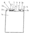
- FIG. 2 shows a cell in cross-section along the plane of a plate 1 a in the plate block, being a cell with terminal post 4 at the beginning or at the end of a number of cells connected together in series.
- Plate 1 a has a lug 2 a directed vertically upwards, which is connected to a cell connector 3 a .
- Plate la is connected electrically via cell connector 3 a to all the other plates of the same plate group.
- the plates of the oppositely poled plate group (not shown) are also connected together electrically-conducting via lugs 2 b and a cell connector 3 b .
- the cell connectors 3 a and 3 b are arranged above the plate block on opposite sides of the cell box.
- Cell connector 3 b has an intercell connector 5 through which the cell is connected to the cell connector of the oppositely poled plate group of the next cell.
- connection of the plates to the cell connectors 3 a and 3 b namely the lugs 2 a and 2 b , are the weakest points of the cell shown.
- these connections tend to pull away or break off.
- FIG. 3 shows the same representation of the cell in FIG. 2 , but with the sealant guide bridge 7 according to the invention and with the sealing compound 8 introduced and hardened.
- the height of the profile of the sealant guide bridge 7 extends vertically over the lowest point of the cell connectors, so that the sealing compound 8 , when introduced in liquid form, completely fills the space between the plate block and the cell connectors, so that after hardening it fixes the relative position of the cell connectors 3 a and 3 b to the plate block.
- the sealing compound runs between the lugs 2 a and 2 b of the plates of the plate block, so that the latter are fixed in it after hardening of the sealing compound 8 .
- the sealant guide bridge 7 ensures that when the sealing compound 8 is introduced it does not spread over the plate block completely, so that a free region 9 is left above the plate block for subsequent filling of the gel electrolyte.
- it is necessary to ensure that it is only introduced around the outside of the sealant guide bridge 7 , i.e. outside of the region 9 that is to be kept free from sealing compound.
- the outer region of the profile of the sealant guide bridge 7 is provided with slanting run-off surfaces, so that as the sealing compound 8 is introduced it flows away from the region 9 that is to be kept free, and under the cell connectors 3 a and 3 b.
- FIGS. 4.1 and 4 . 2 show two different versions of the sealant guide bridges 7 , viewed from above.
- the sealant guide bridge 7 shown in FIG. 4.1 consists of a closed profile 13 around the region 9 that is to be kept free on the surface of a plate block.
- the profile is provided at several points with spacers 11 , which facilitate positioning of the sealant guide bridge 7 in the cell box on the plate block and hold the sealant guide bridge 7 at a distance from the walls of the cell box. Maintaining a lateral gap between the sealant guide bridge 7 and the cell walls ensures that in this version of the sealant guide bridge 7 according to the invention, the sealing compound comes into contact with the side walls of the cell boxes and at the same time with the adjacent surface regions of the plate block. This ensures improved fixation of the plate block in the cell box.
- FIG. 4.2 shows an alternative version of the sealant guide bridge 7 according to the invention, with two substantially rectilinear profile parts 13 , which are joined together by a distance piece 12 and are arranged substantially parallel to one another with a gap between them.
- This version of the sealant guide bridge according to the invention is placed, prior to introduction of the sealing compound, on the plate block in such a way that the two profile parts 13 are each directed to one of the two cell connectors opposite one another in the cell, above the plate block.
- the length of the two profile parts is chosen so that the ends of the profile parts touch the side walls of the cell box, so as to substantially exclude flow of the sealing compound into the region 9 that is to be kept free.
- the version of the sealant guide bridge according to FIG. 4.2 has the advantage over that in FIG.
- the version according to FIG. 4.1 has the advantage that all of the sealing compound applied above the plate block remains continuous and hardens as a single piece, whereas when using the sealant guide bridge according to FIG. 4.2 there are two sealing regions that are separated from one another, which in each case fix the regions of the cell that are sensitive to vibration and jolting on the lugs of the electrode plates and between the plate block and the cell connectors.
- FIGS. 4.3 , 4 . 4 and 4 . 5 each show various profiles of the sealant guide bridges 7 from FIGS. 4.1 and 4 . 2 in cross-section along line A—A.
- Each of the profiles has a run-off surface 10 , over which the sealing compound, as it is introduced, can flow away towards the cell connectors.
- FIG. 4.3 additionally shows a spacer 11 , as described above.
- FIG. 5 shows a cell with a plate block 15 , which also forms part of the accumulator in FIG. 1 , with sealing compound 8 already having been introduced for fixing the individual parts of the cell, in the case of the cell in FIG. 5 .
Landscapes
- Chemical & Material Sciences (AREA)
- Chemical Kinetics & Catalysis (AREA)
- Electrochemistry (AREA)
- General Chemical & Material Sciences (AREA)
- Engineering & Computer Science (AREA)
- Manufacturing & Machinery (AREA)
- Connection Of Batteries Or Terminals (AREA)
- Secondary Cells (AREA)
- Sealing Battery Cases Or Jackets (AREA)
- Battery Mounting, Suspending (AREA)
- Auxiliary Devices For And Details Of Packaging Control (AREA)
Abstract
Description
Claims (13)
Applications Claiming Priority (2)
| Application Number | Priority Date | Filing Date | Title |
|---|---|---|---|
| DE10205658.7 | 2002-02-12 | ||
| DE10205658A DE10205658B4 (en) | 2002-02-12 | 2002-02-12 | Vibration-proof accumulator and method for its production |
Publications (2)
| Publication Number | Publication Date |
|---|---|
| US20030152832A1 US20030152832A1 (en) | 2003-08-14 |
| US6962761B2 true US6962761B2 (en) | 2005-11-08 |
Family
ID=27588546
Family Applications (1)
| Application Number | Title | Priority Date | Filing Date |
|---|---|---|---|
| US10/364,862 Expired - Lifetime US6962761B2 (en) | 2002-02-12 | 2003-02-11 | Vibration-resistant accumulator and method of its manufacture |
Country Status (5)
| Country | Link |
|---|---|
| US (1) | US6962761B2 (en) |
| EP (1) | EP1335443B1 (en) |
| AT (1) | ATE400906T1 (en) |
| DE (2) | DE10205658B4 (en) |
| ES (1) | ES2309243T3 (en) |
Families Citing this family (1)
| Publication number | Priority date | Publication date | Assignee | Title |
|---|---|---|---|---|
| DE102013101527B4 (en) * | 2013-02-15 | 2015-04-02 | Johnson Controls Autobatterie Gmbh & Co. Kgaa | Fixing element, accumulator and method for its production |
Citations (6)
| Publication number | Priority date | Publication date | Assignee | Title |
|---|---|---|---|---|
| US4495259A (en) * | 1983-02-11 | 1985-01-22 | The Gates Rubber Company | Vibration resistant battery |
| DE3533579A1 (en) | 1985-09-20 | 1987-03-26 | Varta Batterie | Electric accumulator (rechargeable battery) |
| JPS63291361A (en) | 1987-05-22 | 1988-11-29 | Shin Kobe Electric Mach Co Ltd | Manufacture of group of plates of lead storage battery |
| DE3833426A1 (en) | 1988-10-01 | 1990-04-05 | Varta Batterie | Electrochemical cell |
| US5607797A (en) * | 1994-05-24 | 1997-03-04 | Matsushita Electric Industrial Co., Ltd. | Lead acid storage battery and method for manufacture thereof |
| JPH10144269A (en) | 1996-11-11 | 1998-05-29 | Furukawa Battery Co Ltd:The | Battery jar cover for adhesive type storage battery and adhesive type storage battery |
-
2002
- 2002-02-12 DE DE10205658A patent/DE10205658B4/en not_active Expired - Fee Related
-
2003
- 2003-01-18 EP EP03001082A patent/EP1335443B1/en not_active Expired - Lifetime
- 2003-01-18 ES ES03001082T patent/ES2309243T3/en not_active Expired - Lifetime
- 2003-01-18 DE DE50310089T patent/DE50310089D1/en not_active Expired - Lifetime
- 2003-01-18 AT AT03001082T patent/ATE400906T1/en not_active IP Right Cessation
- 2003-02-11 US US10/364,862 patent/US6962761B2/en not_active Expired - Lifetime
Patent Citations (6)
| Publication number | Priority date | Publication date | Assignee | Title |
|---|---|---|---|---|
| US4495259A (en) * | 1983-02-11 | 1985-01-22 | The Gates Rubber Company | Vibration resistant battery |
| DE3533579A1 (en) | 1985-09-20 | 1987-03-26 | Varta Batterie | Electric accumulator (rechargeable battery) |
| JPS63291361A (en) | 1987-05-22 | 1988-11-29 | Shin Kobe Electric Mach Co Ltd | Manufacture of group of plates of lead storage battery |
| DE3833426A1 (en) | 1988-10-01 | 1990-04-05 | Varta Batterie | Electrochemical cell |
| US5607797A (en) * | 1994-05-24 | 1997-03-04 | Matsushita Electric Industrial Co., Ltd. | Lead acid storage battery and method for manufacture thereof |
| JPH10144269A (en) | 1996-11-11 | 1998-05-29 | Furukawa Battery Co Ltd:The | Battery jar cover for adhesive type storage battery and adhesive type storage battery |
Also Published As
| Publication number | Publication date |
|---|---|
| EP1335443B1 (en) | 2008-07-09 |
| DE10205658B4 (en) | 2005-10-27 |
| DE50310089D1 (en) | 2008-08-21 |
| DE10205658A1 (en) | 2003-08-21 |
| EP1335443A2 (en) | 2003-08-13 |
| ES2309243T3 (en) | 2008-12-16 |
| EP1335443A3 (en) | 2005-03-30 |
| US20030152832A1 (en) | 2003-08-14 |
| ATE400906T1 (en) | 2008-07-15 |
Similar Documents
| Publication | Publication Date | Title |
|---|---|---|
| KR101050315B1 (en) | Secondary battery module | |
| KR100868255B1 (en) | Terminal-Connecting Means | |
| US6819081B2 (en) | Power source apparatus | |
| CN101542772B (en) | Electric storage device | |
| CN107615517B (en) | Secondary battery pack | |
| KR101688482B1 (en) | Battery unit and battery module using the same | |
| JPS62268054A (en) | Storage battery | |
| KR20090048860A (en) | Battery module | |
| WO2014082853A1 (en) | Battery module having a battery module cover and method for producing a battery module cover of a battery module | |
| EP2913868A1 (en) | Secondary battery and method of manufacturing the same | |
| KR20090000301A (en) | Electrode terminal connecting device and battery module assembly employed with the same | |
| US6962761B2 (en) | Vibration-resistant accumulator and method of its manufacture | |
| US8859135B2 (en) | Battery cell connecting element and method of production thereof | |
| KR101678534B1 (en) | Battery module with insulating member | |
| JP4399917B2 (en) | Lead acid battery and manufacturing method thereof | |
| US11251485B2 (en) | Lead-acid battery | |
| KR20200042243A (en) | Large lead acid battery precursors to improve vibration resistance | |
| US4124745A (en) | Accumulator with plate element having a rib for securing to cell wall | |
| CN105144426B (en) | The manufacture method of retaining element, storage battery and the storage battery | |
| CN219303803U (en) | Battery and battery pack using same | |
| JP4534508B2 (en) | Lead acid battery | |
| US4122244A (en) | Electric storage battery | |
| CN213959084U (en) | Battery module | |
| CN117525699A (en) | Connection structure of battery top cover assembly and sealing assembly | |
| JP2562958B2 (en) | Manufacturing method of lead storage battery |
Legal Events
| Date | Code | Title | Description |
|---|---|---|---|
| AS | Assignment |
Owner name: DEUTSCHE EXIDE STANDBY GMBH, GERMANY Free format text: ASSIGNMENT OF ASSIGNORS INTEREST;ASSIGNORS:KRAMM, FRIEDRICH;IMHOF, WOLFGANG;SCHMIDT-LUKASCH, GUNTER;REEL/FRAME:013820/0760;SIGNING DATES FROM 20030127 TO 20030217 |
|
| STCF | Information on status: patent grant |
Free format text: PATENTED CASE |
|
| CC | Certificate of correction | ||
| FEPP | Fee payment procedure |
Free format text: PAYOR NUMBER ASSIGNED (ORIGINAL EVENT CODE: ASPN); ENTITY STATUS OF PATENT OWNER: LARGE ENTITY |
|
| FPAY | Fee payment |
Year of fee payment: 4 |
|
| AS | Assignment |
Owner name: EXIDE TECHNOLOGIES GMBH, GERMANY Free format text: CHANGE OF NAME;ASSIGNOR:DEUTSCHE EXIDE GMBH;REEL/FRAME:027188/0251 Effective date: 20080616 Owner name: DEUTSCHE EXIDE GMBH, GERMANY Free format text: MERGER;ASSIGNOR:DEUTSCHE EXIDE STANDBY GMBH;REEL/FRAME:027188/0207 Effective date: 20030718 |
|
| FPAY | Fee payment |
Year of fee payment: 8 |
|
| FPAY | Fee payment |
Year of fee payment: 12 |