US6952393B2 - Recording medium and a recording system for the recording medium - Google Patents
Recording medium and a recording system for the recording medium Download PDFInfo
- Publication number
- US6952393B2 US6952393B2 US10/274,199 US27419902A US6952393B2 US 6952393 B2 US6952393 B2 US 6952393B2 US 27419902 A US27419902 A US 27419902A US 6952393 B2 US6952393 B2 US 6952393B2
- Authority
- US
- United States
- Prior art keywords
- land
- information
- signal
- recording
- groove
- Prior art date
- Legal status (The legal status is an assumption and is not a legal conclusion. Google has not performed a legal analysis and makes no representation as to the accuracy of the status listed.)
- Expired - Lifetime, expires
Links
- 238000001514 detection method Methods 0.000 claims abstract description 7
- 239000000758 substrate Substances 0.000 description 12
- 238000004040 coloring Methods 0.000 description 1
- 238000010586 diagram Methods 0.000 description 1
- 239000002184 metal Substances 0.000 description 1
- 230000003287 optical effect Effects 0.000 description 1
- 229920003023 plastic Polymers 0.000 description 1
- 239000004417 polycarbonate Substances 0.000 description 1
- 229920000515 polycarbonate Polymers 0.000 description 1
Images


Classifications
-
- G—PHYSICS
- G11—INFORMATION STORAGE
- G11B—INFORMATION STORAGE BASED ON RELATIVE MOVEMENT BETWEEN RECORD CARRIER AND TRANSDUCER
- G11B7/00—Recording or reproducing by optical means, e.g. recording using a thermal beam of optical radiation by modifying optical properties or the physical structure, reproducing using an optical beam at lower power by sensing optical properties; Record carriers therefor
- G11B7/007—Arrangement of the information on the record carrier, e.g. form of tracks, actual track shape, e.g. wobbled, or cross-section, e.g. v-shaped; Sequential information structures, e.g. sectoring or header formats within a track
-
- G—PHYSICS
- G11—INFORMATION STORAGE
- G11B—INFORMATION STORAGE BASED ON RELATIVE MOVEMENT BETWEEN RECORD CARRIER AND TRANSDUCER
- G11B27/00—Editing; Indexing; Addressing; Timing or synchronising; Monitoring; Measuring tape travel
- G11B27/10—Indexing; Addressing; Timing or synchronising; Measuring tape travel
- G11B27/19—Indexing; Addressing; Timing or synchronising; Measuring tape travel by using information detectable on the record carrier
- G11B27/24—Indexing; Addressing; Timing or synchronising; Measuring tape travel by using information detectable on the record carrier by sensing features on the record carrier other than the transducing track ; sensing signals or marks recorded by another method than the main recording
-
- G—PHYSICS
- G11—INFORMATION STORAGE
- G11B—INFORMATION STORAGE BASED ON RELATIVE MOVEMENT BETWEEN RECORD CARRIER AND TRANSDUCER
- G11B7/00—Recording or reproducing by optical means, e.g. recording using a thermal beam of optical radiation by modifying optical properties or the physical structure, reproducing using an optical beam at lower power by sensing optical properties; Record carriers therefor
- G11B7/004—Recording, reproducing or erasing methods; Read, write or erase circuits therefor
- G11B7/005—Reproducing
- G11B7/0053—Reproducing non-user data, e.g. wobbled address, prepits, BCA
-
- G—PHYSICS
- G11—INFORMATION STORAGE
- G11B—INFORMATION STORAGE BASED ON RELATIVE MOVEMENT BETWEEN RECORD CARRIER AND TRANSDUCER
- G11B7/00—Recording or reproducing by optical means, e.g. recording using a thermal beam of optical radiation by modifying optical properties or the physical structure, reproducing using an optical beam at lower power by sensing optical properties; Record carriers therefor
- G11B7/007—Arrangement of the information on the record carrier, e.g. form of tracks, actual track shape, e.g. wobbled, or cross-section, e.g. v-shaped; Sequential information structures, e.g. sectoring or header formats within a track
- G11B7/00718—Groove and land recording, i.e. user data recorded both in the grooves and on the lands
-
- G—PHYSICS
- G11—INFORMATION STORAGE
- G11B—INFORMATION STORAGE BASED ON RELATIVE MOVEMENT BETWEEN RECORD CARRIER AND TRANSDUCER
- G11B7/00—Recording or reproducing by optical means, e.g. recording using a thermal beam of optical radiation by modifying optical properties or the physical structure, reproducing using an optical beam at lower power by sensing optical properties; Record carriers therefor
- G11B7/24—Record carriers characterised by shape, structure or physical properties, or by the selection of the material
- G11B7/2407—Tracks or pits; Shape, structure or physical properties thereof
- G11B7/24073—Tracks
- G11B7/24079—Width or depth
-
- G—PHYSICS
- G11—INFORMATION STORAGE
- G11B—INFORMATION STORAGE BASED ON RELATIVE MOVEMENT BETWEEN RECORD CARRIER AND TRANSDUCER
- G11B7/00—Recording or reproducing by optical means, e.g. recording using a thermal beam of optical radiation by modifying optical properties or the physical structure, reproducing using an optical beam at lower power by sensing optical properties; Record carriers therefor
- G11B7/24—Record carriers characterised by shape, structure or physical properties, or by the selection of the material
- G11B7/2407—Tracks or pits; Shape, structure or physical properties thereof
- G11B7/24085—Pits
-
- G—PHYSICS
- G11—INFORMATION STORAGE
- G11B—INFORMATION STORAGE BASED ON RELATIVE MOVEMENT BETWEEN RECORD CARRIER AND TRANSDUCER
- G11B2220/00—Record carriers by type
- G11B2220/20—Disc-shaped record carriers
- G11B2220/21—Disc-shaped record carriers characterised in that the disc is of read-only, rewritable, or recordable type
- G11B2220/215—Recordable discs
- G11B2220/216—Rewritable discs
-
- G—PHYSICS
- G11—INFORMATION STORAGE
- G11B—INFORMATION STORAGE BASED ON RELATIVE MOVEMENT BETWEEN RECORD CARRIER AND TRANSDUCER
- G11B2220/00—Record carriers by type
- G11B2220/20—Disc-shaped record carriers
- G11B2220/21—Disc-shaped record carriers characterised in that the disc is of read-only, rewritable, or recordable type
- G11B2220/215—Recordable discs
- G11B2220/218—Write-once discs
-
- G—PHYSICS
- G11—INFORMATION STORAGE
- G11B—INFORMATION STORAGE BASED ON RELATIVE MOVEMENT BETWEEN RECORD CARRIER AND TRANSDUCER
- G11B2220/00—Record carriers by type
- G11B2220/20—Disc-shaped record carriers
- G11B2220/25—Disc-shaped record carriers characterised in that the disc is based on a specific recording technology
- G11B2220/2537—Optical discs
- G11B2220/2562—DVDs [digital versatile discs]; Digital video discs; MMCDs; HDCDs
-
- G—PHYSICS
- G11—INFORMATION STORAGE
- G11B—INFORMATION STORAGE BASED ON RELATIVE MOVEMENT BETWEEN RECORD CARRIER AND TRANSDUCER
- G11B7/00—Recording or reproducing by optical means, e.g. recording using a thermal beam of optical radiation by modifying optical properties or the physical structure, reproducing using an optical beam at lower power by sensing optical properties; Record carriers therefor
- G11B7/08—Disposition or mounting of heads or light sources relatively to record carriers
- G11B7/09—Disposition or mounting of heads or light sources relatively to record carriers with provision for moving the light beam or focus plane for the purpose of maintaining alignment of the light beam relative to the record carrier during transducing operation, e.g. to compensate for surface irregularities of the latter or for track following
- G11B7/0943—Methods and circuits for performing mathematical operations on individual detector segment outputs
Definitions
- the present invention relates to a recording medium and a recording and reproducing system for the recording medium.
- DVD digital versatile disc
- DVD-R DVD WRITE ONCE
- DVD-RW DVD-Re-Writable
- the DVD-R or DVD-RW (hereinafter called DVD) has a spiral or co-axial groove for recording information, a land between the grooves and a plurality of land prepits formed between the grooves.
- the land prepit is provided with various sets of information such as the address.
- An object of the present invention is to provide a recording medium wherein information recorded on the groove and the land prepit can be accurately read out and a system capable of recording and reproducing with accuracy.
- the present invention further provides a recording medium having a circular substrate, grooves formed on the substrate, a land formed between the grooves, a plurality of land prepits formed between the grooves, wherein the groove and the land prepit are formed so as to satisfy following formulae;
- G ⁇ ⁇ w / ( ⁇ / N ⁇ ⁇ A ) ⁇ 0.2093 ⁇ ⁇ L ⁇ ⁇ p / ( ⁇ / N ⁇ ⁇ A ) ⁇ 2 - 0.4342 ⁇ L ⁇ ⁇ p / ( ⁇ / N ⁇ ⁇ A ) + 0.332 - ( - 2.64 ⁇ G ⁇ ⁇ d + 0.1276 )
- G ⁇ ⁇ w / ( ⁇ / N ⁇ ⁇ A ) ⁇ 0.2093 ⁇ ⁇ L ⁇ ⁇ p / ( ⁇ / N ⁇ ⁇ A ) ⁇ 2 - 0.4342 ⁇ L ⁇ ⁇ p / ( ⁇
- the present invention still further provides a system of recording a medium having a circular substrate, grooves formed on the substrate, a land formed between the grooves, a plurality of land prepits formed between the grooves, wherein a wavelength of light for recording information on the medium and a numerical aperture of an objective of the system are provided so as to satisfy following formulae, G ⁇ ⁇ w / ( ⁇ / N ⁇ ⁇ A ) ⁇ 0.2093 ⁇ ⁇ L ⁇ ⁇ p / ( ⁇ / N ⁇ ⁇ A ) ⁇ 2 - 0.4342 ⁇ L ⁇ ⁇ p / ( ⁇ / N ⁇ ⁇ A ) + 0.332 - ( - 2.64 ⁇ G ⁇ ⁇ d + 0.1276 ) G ⁇ ⁇ w / ( ⁇ / N ⁇ ⁇ A ) ⁇ 0.2093 ⁇ ⁇ L ⁇ ⁇ p / ( ⁇ / N ⁇ ⁇ A ) ⁇ 2 - 0.
- FIG. 1 a is a perspective view of an optical DVD for explaining the present invention
- FIG. 1 b is a sectional view of the disc of FIG. 1 a;
- FIG. 2 a is an enlarged plan view showing a part of the disc
- FIG. 2 b is a block diagram of a reproducing system
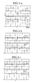
- FIGS. 3 a through 3 c are graphs showing waveforms of a land prepit detection signal and an RF signal
- FIGS. 4 a through 4 c are graphs showing waveforms of a land prepit detection signal and an RF signal detected from recorded mediums.
- FIGS. 5 through 13 are graphs for determining optimum conditions for the land prepit are the groove of the medium.
- the DVD has a transparent plastic substrate 4 made of polycarbonate.
- a transparent plastic substrate 4 made of polycarbonate.
- On the substrate 4 there is formed grooves 1 arranged in the circumferential direction DC, lands 2 between the grooves 1 , and land prepits 3 on the land 2 formed at predetermined intervals.
- Information such as video data or audio data is recorded in the groove, and information such as address is recorded in the prepit.
- a recording layer 5 of organic coloring matter or inorganic metal On the underside of the substrate 4 , there is formed a recording layer 5 of organic coloring matter or inorganic metal, a reflection layer 6 and a protecting layer 7 .
- the laser light is applied to the groove passing through an objective 8 .
- the width Gw of the groove 1 , the length Lp of the land prepit in the circumferential direction, and the depth Gd of the groove are determined to particular values as described hereinafter.
- a light spot SP has a diameter larger than the width Gw of the groove 1 and disposed so that the center of the spot coincides with the center line of the groove 1 .
- information recorded on the land prepit 3 can also be read as shown in FIG. 2 a.
- the reproducing system has a photodetector 9 comprising four elements 9 A, 9 B, 9 C and 9 D for receiving the light reflected from the disc, and adding and subtracting circuits 10 and 11 and an adder 12 .
- the spot of the reflected light is positioned such that the center of the spot coincides with the center of the photodetector 9 .
- the areas A and D in FIG. 2 a read the information on the groove 1
- areas B and C read information on the groove 1 and land prepit 3 .
- the photodetector 9 produces signals A, B, C and D corresponding to the areas A-D.
- FIGS. 3 a , 3 b , 3 c show results of reproduction experiments of the DVD-RW, where amplitude change of the land prepit signal SLp and the RF signal SRF under the condition that the wavelength X of the spot SP and the numerical aperture NA are constant.
- the prepit length Lp is 0.3 ⁇ m and the groove width Gw is 0.25 ⁇ m
- the prepit length Lp is 0.3 ⁇ m
- the groove width Gw is 0.3 ⁇ m
- Lp 0.3 ⁇ m
- Gw 0.4 ⁇ m.
- FIGS. 4 a , 4 b and 4 c show results of experiments of the DVD-RW in which information is recorded in the groove. The conditions are the same as those of FIGS. 3 a - 3 c.
- the groove width Gw, the prepit length Lp and the groove depth Gp are determined to optimum values as follows.
- the groove width Gw, prepit length Lp, groove depth Gd, numerical aperture NA and wavelength ⁇ are determined so that the ratio Gw/( ⁇ /NA) of the groove width Gw to spot diameter ⁇ /NA is set to satisfy both of following formulae (1) and (2).
- the ratio ⁇ /NA of the wavelength ⁇ to the numerical aperture NA indicates a diameter d of spot SP.
- An optimum design of the DVD can be obtained by satisfying the above conditions. Namely, it is possible to detect the RF signal SRE and prepit signal SLp with high accuracy, even if the spot irradiates the groove and prepit.
- FIGS. 5-8 show results of experiments wherein detection accuracy of the land prepit signal SRF changes with the groove width Gw, prepit length Lp, groove depth Gd, wavelength ⁇ and numerical aperture NA.
- the abscissa is the ratio Gw/( ⁇ /NA) of diameter ⁇ /NA to the groove width Gw
- the ordinate is the ratio LPP level/offset of the voltage amplitude of the land prepit signal SLp (LPP level) to the offset level (offset) of the RF signal SRF.
- the groove depth Gd and the prepit length Lp are changed.
- the offset level is a parameter obtained by standardizing the alternating current component of the RF signal SRF of FIGS. 3 a - 3 c with the direct current component of the signal SRF
- the voltage amplitude (LPP level) is a parameter obtained by standardizing the land prepit signal SLp with the direct current component of the RF signal SRF.
- the offset level (offset) is expressed by the following formula (3)
- voltage amplitude (LPP level) is expressed by the formula (4)
- the ratio (LPP level/offset) is expressed by the formula (5).
- the groove depth Gd is changed between 20 ⁇ m-35 ⁇ m by 5 ⁇ m.
- Lp/( ⁇ /NA) 0.128
- Lp/( ⁇ /NA) 0.2515 in FIG. 6 , 0.3815 in FIG. 7 , 0.505 in FIG. 8 .
- FIGS. 9-12 show the relationship between Lp/( ⁇ /NA) and Gw/( ⁇ /NA) with the parameter of the groove depth Gd.
- the line Gwo in FIGS. 9-12 is a line obtained by plotting points where the value of LPP level/offset in FIGS. 5-8 becomes maximum, and the line G+ and line G ⁇ are lines obtained by plotting points where LPP level/offset becomes about 10. Further, the line G+ is the case where LPP level/offset becomes 10 in the right side of FIGS. 5-8 , the line G ⁇ is the case where LPP level/offset becomes 10 in the left side of FIGS. 5-8 .
- the formula (6) shows the most optimum condition.
- the lines G+ and G ⁇ is approximately equal to lines formed by parallely moving the line Gwo.
- FIG. 13 shows the relationship between the groove depth Gd and Gw+/( ⁇ /NA) and the relationship between the groove depth Gd and Gw ⁇ /( ⁇ /NA) in which the parallel moving quantities are set to the ranges Gw+ and Gw ⁇ .
- the range between the lines Gw+ and Gw ⁇ is the optimum design condition.
- the lines Gw+ and Gw ⁇ in FIG. 13 are expressed by following formulae (7) and (8)
- the groove width, groove depth and the prepit length are set to values based on optimum conditions for preventing the land prepit from affecting the detected RF signal.
- the wavelength of laser light and the numeral aperture are set to values based optimum conditions, also. Therefore, it is possible to detect information recorded on the groove and the land prepit with accuracy.
Landscapes
- Optical Record Carriers And Manufacture Thereof (AREA)
- Optical Recording Or Reproduction (AREA)
- Optical Head (AREA)
Abstract
A recording/reproducing medium having grooves, a land formed between the grooves, and land prepits formed on the land in which each of said land prepits has a most optimum design condition where a ratio (LLP Level/offset) between a voltage amplitude (LLP Level) of a land prepit detection signal and an offset level (offset) of an RF signal becomes more than about or where an amplitude change of an RF signal through the land prepit becomes minimum. The recording/reproducing medium can be one of a DVD-R and a DVD-RW.
Description
This application is a Divisional of application Ser. No. 09/758,393, filed Jan. 12, 2001, now U.S. Pat. No. 6,493,313, which in turn is a Continuation of application Ser. No. 09/419,908, filed Oct. 18, 1999, now U.S. Pat. No. 6,181,672, the entire specification, claims, and drawings of which are incorporated herewith by reference.
The present invention relates to a recording medium and a recording and reproducing system for the recording medium.
Heretofore, there is known the DVD (digital versatile disc),the DVD-R (DVD WRITE ONCE) and the DVD-RW (DVD-Re-Writable) as the rewritable disc.
As shown in the Japanese Patent Laid-Open Publication No. 9-17029, the DVD-R or DVD-RW (hereinafter called DVD) has a spiral or co-axial groove for recording information, a land between the grooves and a plurality of land prepits formed between the grooves. The land prepit is provided with various sets of information such as the address.
In such a disc, it is possible to read the information recorded on the groove and the information recorded on the land prepit at the same time.
However, there is a problem that signals reproduced from the information recorded on land prepits affect the RF signal reproduced from the information recorded on the groove as offset.
An object of the present invention is to provide a recording medium wherein information recorded on the groove and the land prepit can be accurately read out and a system capable of recording and reproducing with accuracy.
According to the present invention, there is provided a recording medium having a circular substrate, grooves formed on the substrate, a land formed between the grooves, a plurality of land prepits formed between the grooves, wherein the groove and the land prepit are formed so as to satisfy a following formula,
Gw/(λ/NA)=0.2093{Lp/(λ/NA)}2−0.4342Lp/(λ/NA)+0.332
where Gw is the width of the groove, Lp is the length of the land prepit in a radial direction of the substrate, Gd is the depth of the groove, λ is the wave length of light used in a system for recording information on the recording medium, and NA is the numerical aperture of an objective in the system.
The present invention further provides a recording medium having a circular substrate, grooves formed on the substrate, a land formed between the grooves, a plurality of land prepits formed between the grooves, wherein the groove and the land prepit are formed so as to satisfy following formulae;
where Gw is the width of the groove, Lp is the length of the land prepit in a radial direction of the substrate, Gd is the depth of the groove, λ is the wave length of light used in a system for recording information on the recording medium, and NA is the numerical aperture of an objective in the system.
where Gw is the width of the groove, Lp is the length of the land prepit in a radial direction of the substrate, Gd is the depth of the groove, λ is the wave length of light used in a system for recording information on the recording medium, and NA is the numerical aperture of an objective in the system.
The present invention still further provides a system of recording a medium having a circular substrate, grooves formed on the substrate, a land formed between the grooves, a plurality of land prepits formed between the grooves, wherein a wavelength of light for recording information on the medium and a numerical aperture of an objective of the system are provided so as to satisfy following formulae,
where Gw is the width of the groove, Lp is the length of the land prepit in a radial direction of the substrate, Gd is the depth of the groove.
where Gw is the width of the groove, Lp is the length of the land prepit in a radial direction of the substrate, Gd is the depth of the groove.
Referring to FIGS. 1 a and 1 b, the DVD has a transparent plastic substrate 4 made of polycarbonate. On the substrate 4, there is formed grooves 1 arranged in the circumferential direction DC, lands 2 between the grooves 1, and land prepits 3 on the land 2 formed at predetermined intervals.
Information such as video data or audio data is recorded in the groove, and information such as address is recorded in the prepit.
On the underside of the substrate 4, there is formed a recording layer 5 of organic coloring matter or inorganic metal, a reflection layer 6 and a protecting layer 7. The laser light is applied to the groove passing through an objective 8.
In accordance with the present invention, the width Gw of the groove 1, the length Lp of the land prepit in the circumferential direction, and the depth Gd of the groove are determined to particular values as described hereinafter.
Referring to FIG. 1 showing a part of the DVD and FIG. 2 b showing a reproducing system for the DVD, a light spot SP has a diameter larger than the width Gw of the groove 1 and disposed so that the center of the spot coincides with the center line of the groove 1. Thus, information recorded on the land prepit 3 can also be read as shown in FIG. 2 a.
The reproducing system has a photodetector 9 comprising four elements 9A, 9B, 9C and 9D for receiving the light reflected from the disc, and adding and subtracting circuits 10 and 11 and an adder 12. The spot of the reflected light is positioned such that the center of the spot coincides with the center of the photodetector 9.
Here, the areas A and D in FIG. 2 a read the information on the groove 1, and areas B and C read information on the groove 1 and land prepit 3. The photodetector 9 produces signals A, B, C and D corresponding to the areas A-D.
The adding and subtracting circuit 10 produces a land prepit signal SLp=(A+D)−(B+C), the adding and subtracting circuit 11 produces a tracking error signal STE=(A+D)−(B+C), and the adder 12 produces an RF signal SRF =A+B+C+D.
In the experiment of FIG. 3 a, the prepit length Lp is 0.3 μm and the groove width Gw is 0.25 μm, in FIG. 3 b the prepit length Lp is 0.3 μm, the groove width Gw is 0.3 μm, and in FIG. 3 c Lp=0.3 μm, Gw=0.4 μm.
From the graphs, it will be understood that the voltage amplitudes of the signals SLp and SRF at the irradiation time t change with the prepit length Lp and the groove width Gw.
From the graphs, it will be understood that the voltage amplitudes of the signals SLp and SRF at the irradiation time change with the prepit length Lp and the groove width Gw.
In accordance with the present invention, the groove width Gw, the prepit length Lp and the groove depth Gp are determined to optimum values as follows.
The groove width Gw, prepit length Lp, groove depth Gd, numerical aperture NA and wavelength λ are determined so that the ratio Gw/(λ/NA) of the groove width Gw to spot diameter λ/NA is set to satisfy both of following formulae (1) and (2). The ratio λ/NA of the wavelength λ to the numerical aperture NA indicates a diameter d of spot SP.
An optimum design of the DVD can be obtained by satisfying the above conditions. Namely, it is possible to detect the RF signal SRE and prepit signal SLp with high accuracy, even if the spot irradiates the groove and prepit.
The formulae (1) and (2) are verified with reference to FIGS. 5 through 13 .
In the graph, the abscissa is the ratio Gw/(λ/NA) of diameter λ/NA to the groove width Gw, and the ordinate is the ratio LPP level/offset of the voltage amplitude of the land prepit signal SLp (LPP level) to the offset level (offset) of the RF signal SRF. In addition, the groove depth Gd and the prepit length Lp are changed.
The offset level (offset) is a parameter obtained by standardizing the alternating current component of the RF signal SRF of FIGS. 3 a-3 c with the direct current component of the signal SRF, and the voltage amplitude (LPP level) is a parameter obtained by standardizing the land prepit signal SLp with the direct current component of the RF signal SRF.
If the alternating current of the RF signal SRF is expressed by SRF (AC), the offset level (offset) is expressed by the following formula (3), voltage amplitude (LPP level) is expressed by the formula (4), and the ratio (LPP level/offset) is expressed by the formula (5).
offset=(SRF(AC)/SRF) (3)
LPP level=(SLP/SRF) (4)
LPP level/offset=(SLP/SRF(AC)) (5)
offset=(SRF(AC)/SRF) (3)
LPP level=(SLP/SRF) (4)
LPP level/offset=(SLP/SRF(AC)) (5)
In FIGS. 5-8 , the groove depth Gd is changed between 20 μm-35 μm by 5 μm. In FIG. 5 , Lp/(λ/NA)=0.128, Lp/(λ/NA)=0.2515 in FIG. 6 , 0.3815 in FIG. 7 , 0.505 in FIG. 8.
It is confirmed that the optimum design in the condition when the value of LPP level/offset indicating the detecting accuracy of the land prepit detection signal SLp and RF signal SRF is about 10, namely LPP level/offset≐10.
The line Gwo in FIGS. 9-12 is a line obtained by plotting points where the value of LPP level/offset in FIGS. 5-8 becomes maximum, and the line G+ and line G− are lines obtained by plotting points where LPP level/offset becomes about 10. Further, the line G+ is the case where LPP level/offset becomes 10 in the right side of FIGS. 5-8 , the line G− is the case where LPP level/offset becomes 10 in the left side of FIGS. 5-8 .
Therefore, it is understood that the ranges Gw+ and Gw− between the lines G+ and G− is the optimum design conditions. The line Gwo does not largely change, it can be expressed by the following formula (6).
Gw/(λ/NA)=0.2093{Lp/(λ/NA)}2−0.4342Lp/(λ/NA)+0.332 (6)
Gw/(λ/NA)=0.2093{Lp/(λ/NA)}2−0.4342Lp/(λ/NA)+0.332 (6)
The formula (6) shows the most optimum condition. The lines G+ and G− is approximately equal to lines formed by parallely moving the line Gwo.
Gw/(λ/NA)=−4.48Gd+0.2112 (7)
Gw/(λ/NA)=−2.64Gd+0.1276 (8)
Gw/(λ/NA)=−2.64Gd+0.1276 (8)
The above described formulae (1) and (2) are obtained by obtaining the range between the lines Gw+ and Gw−.
In accordance with the present invention, the groove width, groove depth and the prepit length are set to values based on optimum conditions for preventing the land prepit from affecting the detected RF signal. And, in accordance with the present invention, the wavelength of laser light and the numeral aperture are set to values based optimum conditions, also. Therefore, it is possible to detect information recorded on the groove and the land prepit with accuracy.
While the invention has been described in conjunction with preferred specific embodiment thereof, it will be understood that this description is intended to illustrate and not limit the scope of the invention, which is defined by the following claims.
Claims (9)
1. A recording/reproducing medium having grooves, a land formed between the grooves, and land prepits formed on the land, wherein
each of said land prepits has a most optimum design condition where an amplitude change of an RF signal through the land prepit becomes minimum.
2. The recording/reproducing medium according to claim 1 , wherein the recording/reproducing medium is one of a DVD-R and a DVD-RW.
3. A recording medium comprising:
an information recording track; and
preformed information which is formed on a portion deviated from the information recording track in a radial direction,
wherein the preformed information has a most optimum design condition where an amplitude change of an RF signal through the preformed information is minimalized.
4. The medium according to claim 1 , wherein the most optimum design condition is determined in terms of a length of the preformed information in a circumferential direction, and a width and a depth of the information recording track.
5. The medium according to claim 3 , wherein the most optimum design condition is determined in terms of a length of the preformed information in a circumferential direction, and a width and a depth of the information recording track.
6. A system for recording information on a recording medium including grooves, a land formed between the grooves, and land prepits formed on the land, wherein each land prepit has an optimum design condition where an amplitude change of an RF signal through said land prepit is minimized.
7. A system for recording information on a recording medium including an information recording track, and preformed information which is formed on a portion deviated from the information recording track in a radial direction, wherein the preformed information has an optimum design condition where an amplitude change of an RF signal through the preformed information is minimized.
8. The system according to claim 6 , comprising:
an objective which forms a light spot on the groove, the light spot having a diameter larger than a width of the groove;
a photodetector which receives light reflected from the recording medium, and generates a photodetection signal; and
an operation circuit which generates a land prepit detection signal and the RF signal based on the photodetection signal.
9. The system according to claim 7 , comprising:
an objective which forms a light spot on the information recording track, the light spot having a diameter larger than a width of the information recording track;
a photodetector which receives light reflected from the recording medium, and generates a photodetection signal; and
an operation circuit which generates a preformed information detection signal and the RF signal based on the photodetection signal.
Priority Applications (1)
| Application Number | Priority Date | Filing Date | Title |
|---|---|---|---|
| US10/274,199 US6952393B2 (en) | 1998-10-23 | 2002-10-21 | Recording medium and a recording system for the recording medium |
Applications Claiming Priority (5)
| Application Number | Priority Date | Filing Date | Title |
|---|---|---|---|
| JP10-301965 | 1998-10-23 | ||
| JP30196598A JP4372867B2 (en) | 1998-10-23 | 1998-10-23 | Optical disc and recording / reproducing apparatus |
| US09/419,908 US6181672B1 (en) | 1998-10-23 | 1999-10-18 | Recording medium and a recording system for the recording medium |
| US09/758,393 US6493313B2 (en) | 1998-10-23 | 2001-01-12 | Recording medium having grooves and prepits and a recording system for the recording medium |
| US10/274,199 US6952393B2 (en) | 1998-10-23 | 2002-10-21 | Recording medium and a recording system for the recording medium |
Related Parent Applications (1)
| Application Number | Title | Priority Date | Filing Date |
|---|---|---|---|
| US09/758,393 Division US6493313B2 (en) | 1998-10-23 | 2001-01-12 | Recording medium having grooves and prepits and a recording system for the recording medium |
Publications (2)
| Publication Number | Publication Date |
|---|---|
| US20030053406A1 US20030053406A1 (en) | 2003-03-20 |
| US6952393B2 true US6952393B2 (en) | 2005-10-04 |
Family
ID=17903267
Family Applications (3)
| Application Number | Title | Priority Date | Filing Date |
|---|---|---|---|
| US09/419,908 Expired - Lifetime US6181672B1 (en) | 1998-10-23 | 1999-10-18 | Recording medium and a recording system for the recording medium |
| US09/758,393 Expired - Fee Related US6493313B2 (en) | 1998-10-23 | 2001-01-12 | Recording medium having grooves and prepits and a recording system for the recording medium |
| US10/274,199 Expired - Lifetime US6952393B2 (en) | 1998-10-23 | 2002-10-21 | Recording medium and a recording system for the recording medium |
Family Applications Before (2)
| Application Number | Title | Priority Date | Filing Date |
|---|---|---|---|
| US09/419,908 Expired - Lifetime US6181672B1 (en) | 1998-10-23 | 1999-10-18 | Recording medium and a recording system for the recording medium |
| US09/758,393 Expired - Fee Related US6493313B2 (en) | 1998-10-23 | 2001-01-12 | Recording medium having grooves and prepits and a recording system for the recording medium |
Country Status (5)
| Country | Link |
|---|---|
| US (3) | US6181672B1 (en) |
| EP (2) | EP0996118B1 (en) |
| JP (1) | JP4372867B2 (en) |
| CN (3) | CN1175405C (en) |
| DE (2) | DE69920368T2 (en) |
Cited By (4)
| Publication number | Priority date | Publication date | Assignee | Title |
|---|---|---|---|---|
| US20040141454A1 (en) * | 2002-11-05 | 2004-07-22 | Pioneer Corporation | Information recording medium |
| US20090073834A1 (en) * | 2001-09-29 | 2009-03-19 | Samsung Electronics Co., Ltd. | Method of and apparatus for recording data on optical recording medium |
| US8568152B1 (en) | 2012-04-19 | 2013-10-29 | Pass & Seymour, Inc. | Shutter assembly for electrical devices |
| US8737025B2 (en) | 2003-01-09 | 2014-05-27 | Pass & Seymour, Inc. | Protective electrical wiring device with tamper resistant shutters |
Families Citing this family (21)
| Publication number | Priority date | Publication date | Assignee | Title |
|---|---|---|---|---|
| JP4372867B2 (en) * | 1998-10-23 | 2009-11-25 | パイオニア株式会社 | Optical disc and recording / reproducing apparatus |
| DE60033464T2 (en) * | 1999-04-08 | 2007-10-04 | Pioneer Corporation | Optical recording medium |
| US6535477B1 (en) | 1999-06-28 | 2003-03-18 | Pioneer Corporation | Optical recording medium having groove and land tracks, and method of manufacturing the same |
| KR20010097980A (en) * | 2000-04-27 | 2001-11-08 | 이진섭 | Constant output channel power gain flattened optical amplifier |
| JP4136280B2 (en) * | 2000-07-04 | 2008-08-20 | パイオニア株式会社 | Optical recording medium, manufacturing method and manufacturing apparatus |
| JP2002237102A (en) | 2000-07-07 | 2002-08-23 | Tdk Corp | Optical recording medium and manufacturing method thereof |
| JP4226204B2 (en) | 2000-09-14 | 2009-02-18 | パイオニア株式会社 | Optical recording medium, manufacturing apparatus and manufacturing method thereof |
| JP2002140840A (en) * | 2000-11-01 | 2002-05-17 | Pioneer Electronic Corp | Optical disk and original disk manufacturing device |
| TW577072B (en) * | 2001-07-12 | 2004-02-21 | Tdk Corp | Optical recording disc |
| AU2003257848A1 (en) * | 2002-08-26 | 2004-04-30 | Taiyo Yuden Co., Ltd. | Optical information recording medium |
| JP4598355B2 (en) * | 2002-10-10 | 2010-12-15 | ソニー株式会社 | Disk drive device and pre-pit detection method |
| EP1494216B1 (en) * | 2003-06-10 | 2008-06-04 | Thomson Licensing | Method for land pre-pit recovery |
| EP1486954A1 (en) * | 2003-06-10 | 2004-12-15 | Deutsche Thomson-Brandt Gmbh | Method for land pre-pit recovery |
| DE602004014217D1 (en) | 2003-06-10 | 2008-07-17 | Thomson Licensing | Procedure for the recovery of land pre-well |
| CN101015005A (en) * | 2004-06-22 | 2007-08-08 | 皇家飞利浦电子股份有限公司 | Recording system having improved prepit detection |
| KR100594725B1 (en) * | 2004-09-08 | 2006-06-30 | 삼성전자주식회사 | Optical recording apparatus and method for searching data recording position by adjusting tracking level |
| JP4621550B2 (en) * | 2005-06-24 | 2011-01-26 | 東芝マイクロエレクトロニクス株式会社 | Error correction device for optical disk device |
| US7613983B2 (en) | 2005-06-24 | 2009-11-03 | Kabushiki Kaisha Toshiba | Error correction device of optical disk unit |
| JP4810572B2 (en) * | 2006-05-30 | 2011-11-09 | パイオニア株式会社 | Recordable information recording medium, information recording apparatus, and information recording method |
| JP4600434B2 (en) * | 2007-06-11 | 2010-12-15 | 日本ビクター株式会社 | Optical information recording medium |
| JP4609781B2 (en) * | 2008-04-30 | 2011-01-12 | 日本ビクター株式会社 | Optical information recording medium |
Citations (7)
| Publication number | Priority date | Publication date | Assignee | Title |
|---|---|---|---|---|
| US5282184A (en) | 1991-03-29 | 1994-01-25 | Konica Corporation | Focus control device of an optical disk apparatus |
| US5448552A (en) | 1992-09-29 | 1995-09-05 | Pioneer Electronic Corporation | Super resolution information reproduction by tracking address information in normal resolution |
| JPH0917029A (en) | 1995-06-26 | 1997-01-17 | Pioneer Electron Corp | Optical disc, its reader, and optical disc manufacturing method |
| US5617406A (en) | 1994-02-25 | 1997-04-01 | Pioneer Electronic Corporation | Optical disc with heat blocking bands between tracks |
| US6104682A (en) | 1998-07-23 | 2000-08-15 | Matsushita Electric Industrial Co., Ltd. | Disk apparatus having a data reproducing system using a digital PLL |
| US6144625A (en) | 1997-04-25 | 2000-11-07 | Pioneer Electric Corporation | Optical disc discriminating system |
| US6272089B1 (en) | 1998-03-26 | 2001-08-07 | Pioneer Electronic Corporation | Pre-pit detecting apparatus |
Family Cites Families (9)
| Publication number | Priority date | Publication date | Assignee | Title |
|---|---|---|---|---|
| JPH06333239A (en) * | 1993-05-20 | 1994-12-02 | Pioneer Electron Corp | Optical recording medium and information recorder |
| US5959963A (en) * | 1994-01-19 | 1999-09-28 | Kabushiki Kaisha Toshiba | Optical disk and optical disk apparatus |
| JP2788022B2 (en) * | 1995-02-14 | 1998-08-20 | 株式会社日立製作所 | Optical recording medium |
| JPH0981965A (en) * | 1995-09-18 | 1997-03-28 | Hitachi Maxell Ltd | Optical recording medium and tracking method |
| JP3703569B2 (en) * | 1996-04-02 | 2005-10-05 | ソニー株式会社 | Optical recording medium, recording / reproducing method thereof, and recording / reproducing apparatus |
| JP3769829B2 (en) * | 1996-08-29 | 2006-04-26 | ソニー株式会社 | Playback apparatus and playback method |
| JP3685922B2 (en) * | 1997-11-05 | 2005-08-24 | Tdk株式会社 | Optical recording medium and recording method therefor |
| EP0926664B1 (en) * | 1997-12-26 | 2006-05-31 | Kabushiki Kaisha Toshiba | Optical disk and optical disk apparatus |
| JP4372867B2 (en) * | 1998-10-23 | 2009-11-25 | パイオニア株式会社 | Optical disc and recording / reproducing apparatus |
-
1998
- 1998-10-23 JP JP30196598A patent/JP4372867B2/en not_active Expired - Fee Related
-
1999
- 1999-10-18 US US09/419,908 patent/US6181672B1/en not_active Expired - Lifetime
- 1999-10-21 EP EP99121065A patent/EP0996118B1/en not_active Expired - Lifetime
- 1999-10-21 DE DE69920368T patent/DE69920368T2/en not_active Expired - Lifetime
- 1999-10-21 EP EP04022466A patent/EP1486958B1/en not_active Expired - Lifetime
- 1999-10-21 DE DE69940677T patent/DE69940677D1/en not_active Expired - Lifetime
- 1999-10-25 CN CNB991236238A patent/CN1175405C/en not_active Expired - Fee Related
- 1999-10-25 CN CNB2004100797867A patent/CN100568357C/en not_active Expired - Fee Related
- 1999-10-25 CN CNB2005100775896A patent/CN100342438C/en not_active Expired - Fee Related
-
2001
- 2001-01-12 US US09/758,393 patent/US6493313B2/en not_active Expired - Fee Related
-
2002
- 2002-10-21 US US10/274,199 patent/US6952393B2/en not_active Expired - Lifetime
Patent Citations (8)
| Publication number | Priority date | Publication date | Assignee | Title |
|---|---|---|---|---|
| US5282184A (en) | 1991-03-29 | 1994-01-25 | Konica Corporation | Focus control device of an optical disk apparatus |
| US5448552A (en) | 1992-09-29 | 1995-09-05 | Pioneer Electronic Corporation | Super resolution information reproduction by tracking address information in normal resolution |
| US5617406A (en) | 1994-02-25 | 1997-04-01 | Pioneer Electronic Corporation | Optical disc with heat blocking bands between tracks |
| JPH0917029A (en) | 1995-06-26 | 1997-01-17 | Pioneer Electron Corp | Optical disc, its reader, and optical disc manufacturing method |
| US6144625A (en) | 1997-04-25 | 2000-11-07 | Pioneer Electric Corporation | Optical disc discriminating system |
| US6603720B1 (en) * | 1997-04-25 | 2003-08-05 | Pioneer Electronic Corporation | Optical disc discriminating system |
| US6272089B1 (en) | 1998-03-26 | 2001-08-07 | Pioneer Electronic Corporation | Pre-pit detecting apparatus |
| US6104682A (en) | 1998-07-23 | 2000-08-15 | Matsushita Electric Industrial Co., Ltd. | Disk apparatus having a data reproducing system using a digital PLL |
Non-Patent Citations (2)
| Title |
|---|
| Patent Abstracts of Japan. vol. 1997, No. 05, May 30, 1997 for JP 9 017029 published Jan. 17, 1997. |
| US 6,567,356, 5/2003, Kuroda et al. (withdrawn) * |
Cited By (6)
| Publication number | Priority date | Publication date | Assignee | Title |
|---|---|---|---|---|
| US20090073834A1 (en) * | 2001-09-29 | 2009-03-19 | Samsung Electronics Co., Ltd. | Method of and apparatus for recording data on optical recording medium |
| US8416665B2 (en) | 2001-09-29 | 2013-04-09 | Samsung Electronics Co., Ltd. | Method of and apparatus for recording data on optical recording medium |
| US20040141454A1 (en) * | 2002-11-05 | 2004-07-22 | Pioneer Corporation | Information recording medium |
| US7260052B2 (en) * | 2002-11-05 | 2007-08-21 | Pioneer Corporation | Information recording medium |
| US8737025B2 (en) | 2003-01-09 | 2014-05-27 | Pass & Seymour, Inc. | Protective electrical wiring device with tamper resistant shutters |
| US8568152B1 (en) | 2012-04-19 | 2013-10-29 | Pass & Seymour, Inc. | Shutter assembly for electrical devices |
Also Published As
| Publication number | Publication date |
|---|---|
| DE69940677D1 (en) | 2009-05-14 |
| US6493313B2 (en) | 2002-12-10 |
| JP2000132868A (en) | 2000-05-12 |
| CN1722265A (en) | 2006-01-18 |
| CN1601629A (en) | 2005-03-30 |
| CN100342438C (en) | 2007-10-10 |
| EP0996118A2 (en) | 2000-04-26 |
| DE69920368D1 (en) | 2004-10-28 |
| CN1175405C (en) | 2004-11-10 |
| CN100568357C (en) | 2009-12-09 |
| CN1252595A (en) | 2000-05-10 |
| EP0996118B1 (en) | 2004-09-22 |
| EP1486958A2 (en) | 2004-12-15 |
| HK1081718A1 (en) | 2006-05-19 |
| JP4372867B2 (en) | 2009-11-25 |
| DE69920368T2 (en) | 2006-02-23 |
| EP1486958B1 (en) | 2009-04-01 |
| EP0996118A3 (en) | 2001-07-25 |
| EP1486958A3 (en) | 2005-03-30 |
| HK1073527A1 (en) | 2005-10-07 |
| US6181672B1 (en) | 2001-01-30 |
| US20010002899A1 (en) | 2001-06-07 |
| US20030053406A1 (en) | 2003-03-20 |
Similar Documents
| Publication | Publication Date | Title |
|---|---|---|
| US6952393B2 (en) | Recording medium and a recording system for the recording medium | |
| US5602823A (en) | Optical recording medium having pre-formatted patterns arrange by shifting phases | |
| JP3929207B2 (en) | Pre-pit detection device for optical recording medium | |
| EP0944046A2 (en) | Pre-pit detecting apparatus | |
| US6590857B2 (en) | Optical disk | |
| US6549511B1 (en) | Optical disk medium having features for radial tilt detection and apparatus for measuring radial tilt | |
| EP0881631B1 (en) | Optical disc and optical disc device | |
| US6404729B1 (en) | Optical disc | |
| JPH09102143A (en) | optical disk | |
| US6937550B2 (en) | Information recording medium, information reproduction apparatus, and information reproduction method | |
| EP1094452B1 (en) | Method and apparatus for detection of direction of movement of laser spot in optical disc recording/reproducing device | |
| US7113460B2 (en) | Optical disk having pits of different depths formed therein, optical disk reproducing apparatus for reproducing the optical disk, and method of tracking the optical disk | |
| KR20020050559A (en) | Method for generating monitoring signal of optical recording/reproducing system and apparatus thereof | |
| KR100327203B1 (en) | Optical disc recording media having tilt dection pattern | |
| EP1026673B1 (en) | Optical recording medium drive | |
| US6224959B1 (en) | Optical disc | |
| US6424612B1 (en) | Reproducing method and apparatus for optical disk | |
| US6147952A (en) | Optical disk apparatus for reproducing information from an optical recording medium | |
| KR19990077952A (en) | Optical disk device | |
| HK1073527B (en) | Recording medium and recording system for the recording medium | |
| KR100386040B1 (en) | Optical recording medium | |
| JP2892326B2 (en) | Optical disk drive | |
| US7420895B2 (en) | Signal detection method and apparatus and optical recording and/or reproducing apparatus using the same | |
| JP2915855B2 (en) | Optical disk drive | |
| WO2004025627A2 (en) | Apparatus and method for scanning an information track and record carrier |
Legal Events
| Date | Code | Title | Description |
|---|---|---|---|
| FEPP | Fee payment procedure |
Free format text: PAYOR NUMBER ASSIGNED (ORIGINAL EVENT CODE: ASPN); ENTITY STATUS OF PATENT OWNER: LARGE ENTITY |
|
| STCF | Information on status: patent grant |
Free format text: PATENTED CASE |
|
| FPAY | Fee payment |
Year of fee payment: 4 |
|
| FPAY | Fee payment |
Year of fee payment: 8 |
|
| FPAY | Fee payment |
Year of fee payment: 12 |