US6951592B2 - Method of forming a fabric covered pad for wall panel - Google Patents
Method of forming a fabric covered pad for wall panel Download PDFInfo
- Publication number
- US6951592B2 US6951592B2 US10/267,392 US26739202A US6951592B2 US 6951592 B2 US6951592 B2 US 6951592B2 US 26739202 A US26739202 A US 26739202A US 6951592 B2 US6951592 B2 US 6951592B2
- Authority
- US
- United States
- Prior art keywords
- blank
- frame
- grooves
- edge
- sheet
- Prior art date
- Legal status (The legal status is an assumption and is not a legal conclusion. Google has not performed a legal analysis and makes no representation as to the accuracy of the status listed.)
- Expired - Lifetime, expires
Links
Images


Classifications
-
- B—PERFORMING OPERATIONS; TRANSPORTING
- B32—LAYERED PRODUCTS
- B32B—LAYERED PRODUCTS, i.e. PRODUCTS BUILT-UP OF STRATA OF FLAT OR NON-FLAT, e.g. CELLULAR OR HONEYCOMB, FORM
- B32B5/00—Layered products characterised by the non- homogeneity or physical structure, i.e. comprising a fibrous, filamentary, particulate or foam layer; Layered products characterised by having a layer differing constitutionally or physically in different parts
- B32B5/22—Layered products characterised by the non- homogeneity or physical structure, i.e. comprising a fibrous, filamentary, particulate or foam layer; Layered products characterised by having a layer differing constitutionally or physically in different parts characterised by the presence of two or more layers which are next to each other and are fibrous, filamentary, formed of particles or foamed
-
- E—FIXED CONSTRUCTIONS
- E04—BUILDING
- E04B—GENERAL BUILDING CONSTRUCTIONS; WALLS, e.g. PARTITIONS; ROOFS; FLOORS; CEILINGS; INSULATION OR OTHER PROTECTION OF BUILDINGS
- E04B2/00—Walls, e.g. partitions, for buildings; Wall construction with regard to insulation; Connections specially adapted to walls
- E04B2/74—Removable non-load-bearing partitions; Partitions with a free upper edge
- E04B2/7407—Removable non-load-bearing partitions; Partitions with a free upper edge assembled using frames with infill panels or coverings only; made-up of panels and a support structure incorporating posts
- E04B2/7416—Removable non-load-bearing partitions; Partitions with a free upper edge assembled using frames with infill panels or coverings only; made-up of panels and a support structure incorporating posts with free upper edge, e.g. for use as office space dividers
- E04B2/7422—Removable non-load-bearing partitions; Partitions with a free upper edge assembled using frames with infill panels or coverings only; made-up of panels and a support structure incorporating posts with free upper edge, e.g. for use as office space dividers with separate framed panels without intermediary support posts
-
- E—FIXED CONSTRUCTIONS
- E04—BUILDING
- E04B—GENERAL BUILDING CONSTRUCTIONS; WALLS, e.g. PARTITIONS; ROOFS; FLOORS; CEILINGS; INSULATION OR OTHER PROTECTION OF BUILDINGS
- E04B2/00—Walls, e.g. partitions, for buildings; Wall construction with regard to insulation; Connections specially adapted to walls
- E04B2/74—Removable non-load-bearing partitions; Partitions with a free upper edge
- E04B2002/7461—Details of connection of sheet panels to frame or posts
- E04B2002/7466—Details of connection of sheet panels to frame or posts using hooks
-
- E—FIXED CONSTRUCTIONS
- E04—BUILDING
- E04B—GENERAL BUILDING CONSTRUCTIONS; WALLS, e.g. PARTITIONS; ROOFS; FLOORS; CEILINGS; INSULATION OR OTHER PROTECTION OF BUILDINGS
- E04B2/00—Walls, e.g. partitions, for buildings; Wall construction with regard to insulation; Connections specially adapted to walls
- E04B2/74—Removable non-load-bearing partitions; Partitions with a free upper edge
- E04B2002/7487—Partitions with slotted profiles
-
- Y—GENERAL TAGGING OF NEW TECHNOLOGICAL DEVELOPMENTS; GENERAL TAGGING OF CROSS-SECTIONAL TECHNOLOGIES SPANNING OVER SEVERAL SECTIONS OF THE IPC; TECHNICAL SUBJECTS COVERED BY FORMER USPC CROSS-REFERENCE ART COLLECTIONS [XRACs] AND DIGESTS
- Y10—TECHNICAL SUBJECTS COVERED BY FORMER USPC
- Y10T—TECHNICAL SUBJECTS COVERED BY FORMER US CLASSIFICATION
- Y10T156/00—Adhesive bonding and miscellaneous chemical manufacture
- Y10T156/10—Methods of surface bonding and/or assembly therefor
- Y10T156/1002—Methods of surface bonding and/or assembly therefor with permanent bending or reshaping or surface deformation of self sustaining lamina
- Y10T156/1026—Methods of surface bonding and/or assembly therefor with permanent bending or reshaping or surface deformation of self sustaining lamina with slitting or removal of material at reshaping area prior to reshaping
-
- Y—GENERAL TAGGING OF NEW TECHNOLOGICAL DEVELOPMENTS; GENERAL TAGGING OF CROSS-SECTIONAL TECHNOLOGIES SPANNING OVER SEVERAL SECTIONS OF THE IPC; TECHNICAL SUBJECTS COVERED BY FORMER USPC CROSS-REFERENCE ART COLLECTIONS [XRACs] AND DIGESTS
- Y10—TECHNICAL SUBJECTS COVERED BY FORMER USPC
- Y10T—TECHNICAL SUBJECTS COVERED BY FORMER US CLASSIFICATION
- Y10T156/00—Adhesive bonding and miscellaneous chemical manufacture
- Y10T156/10—Methods of surface bonding and/or assembly therefor
- Y10T156/1002—Methods of surface bonding and/or assembly therefor with permanent bending or reshaping or surface deformation of self sustaining lamina
- Y10T156/1028—Methods of surface bonding and/or assembly therefor with permanent bending or reshaping or surface deformation of self sustaining lamina by bending, drawing or stretch forming sheet to assume shape of configured lamina while in contact therewith
- Y10T156/103—Encasing or enveloping the configured lamina
-
- Y—GENERAL TAGGING OF NEW TECHNOLOGICAL DEVELOPMENTS; GENERAL TAGGING OF CROSS-SECTIONAL TECHNOLOGIES SPANNING OVER SEVERAL SECTIONS OF THE IPC; TECHNICAL SUBJECTS COVERED BY FORMER USPC CROSS-REFERENCE ART COLLECTIONS [XRACs] AND DIGESTS
- Y10—TECHNICAL SUBJECTS COVERED BY FORMER USPC
- Y10T—TECHNICAL SUBJECTS COVERED BY FORMER US CLASSIFICATION
- Y10T156/00—Adhesive bonding and miscellaneous chemical manufacture
- Y10T156/10—Methods of surface bonding and/or assembly therefor
- Y10T156/1002—Methods of surface bonding and/or assembly therefor with permanent bending or reshaping or surface deformation of self sustaining lamina
- Y10T156/1043—Subsequent to assembly
- Y10T156/1044—Subsequent to assembly of parallel stacked sheets only
-
- Y—GENERAL TAGGING OF NEW TECHNOLOGICAL DEVELOPMENTS; GENERAL TAGGING OF CROSS-SECTIONAL TECHNOLOGIES SPANNING OVER SEVERAL SECTIONS OF THE IPC; TECHNICAL SUBJECTS COVERED BY FORMER USPC CROSS-REFERENCE ART COLLECTIONS [XRACs] AND DIGESTS
- Y10—TECHNICAL SUBJECTS COVERED BY FORMER USPC
- Y10T—TECHNICAL SUBJECTS COVERED BY FORMER US CLASSIFICATION
- Y10T428/00—Stock material or miscellaneous articles
- Y10T428/24—Structurally defined web or sheet [e.g., overall dimension, etc.]
- Y10T428/24174—Structurally defined web or sheet [e.g., overall dimension, etc.] including sheet or component perpendicular to plane of web or sheet
-
- Y—GENERAL TAGGING OF NEW TECHNOLOGICAL DEVELOPMENTS; GENERAL TAGGING OF CROSS-SECTIONAL TECHNOLOGIES SPANNING OVER SEVERAL SECTIONS OF THE IPC; TECHNICAL SUBJECTS COVERED BY FORMER USPC CROSS-REFERENCE ART COLLECTIONS [XRACs] AND DIGESTS
- Y10—TECHNICAL SUBJECTS COVERED BY FORMER USPC
- Y10T—TECHNICAL SUBJECTS COVERED BY FORMER US CLASSIFICATION
- Y10T428/00—Stock material or miscellaneous articles
- Y10T428/24—Structurally defined web or sheet [e.g., overall dimension, etc.]
- Y10T428/2419—Fold at edge
- Y10T428/24215—Acute or reverse fold of exterior component
- Y10T428/24231—At opposed marginal edges
Definitions
- This invention relates to a cover pad for attachment to a wall such as for attachment to the frame of an upright space divider wall panel and, more specifically, to an improved pad structure and a process of manufacturing same.
- Interior space dividing wall systems as used in offices and the like typically incorporate a plurality of interconnected portable wall panels which often permit accessories such as worksurfaces, storage units and other devices or structures to be mounted thereon.
- the wall panels generally include an interior upright frame which mounts, frequently releasably, cover pads or tiles on one or both sides thereof.
- the cover pads are typically provided with an outer cloth or fabric covering to provide the wall panel with a desirable appearance.
- Such cover pads require an internal supporting and rigidifying structure which may be defined by a rigid sheet of material such as metal, particle board, mineral board or the like, and/or an internal frame similar to an open picture frame.
- the internal structure of the pad then has the external face thereof covered with a thin sheet of flexible fabric or similar covering material.
- the flexible covering is also typically wrapped around the edges and corners of the internal structure. The covering is then secured by clips or adhesive to the internal structure.
- Cover pads having constructions similar to those described above are well known, but as is well recognized in this industry, such pads possess structural and manufacturing complexities which cause the construction of such pads to be undesirably inefficient and costly, and which also result in the pads having a less than desirable appearance, particularly at the corners.
- the attachment of the flexible covering i.e. the fabric
- the wrapping and securing of the fabric around the edges is further complicated by the necessity of folding and inwardly tucking the excess fabric which exists at the corners, which operation generally requires significant manual handing of the fabric and often results in fabric wrapped corners of inconsistent quality and hence less than desired appearance.
- the internal structure of the pad and the typical requirement for an internal frame cause the pad to have an undesired number of parts which increases manufacturing complexity and cost.
- the present invention relates to improvements associated with cover pads for use on upright walls, which improvements simplify the construction and manufacturing of the pad so as to overcome or at least minimize some of the disadvantages associated with presently known pads.
- the pad of this invention provides an improved internal support which is of simplified construction, for example the center support and the surrounding frame being made of a one-piece monolithic support structure, which permits the flexible covering or fabric to be attached to the center support and the exterior side surfaces of the edge frame while the fabric and support structure are in a flat and planar condition, following which the edge frame is folded and secured into position around the center support.
- the internal support structure for the pad when in a flat condition, has voids at the corners so that the fabric can be easily tucked into the corners prior to the edge frame being folded into its closing or frame-defining position.
- FIG. 1 is a perspective view of a known wall panel system having one or more cover pads associated with one and typically both sides thereof.
- FIG. 2 is a perspective view which illustrates the internal frame of a known wall panel, and further illustrates a typical cover pad shown in a separated position relative to the frame.
- FIG. 3 is a front perspective view of a cover pad according to the present invention.
- FIGS. 4 and 5 are enlarged fragmentary views taken along lines 4 — 4 and 5 — 5 , respectively, in FIG. 3 .
- FIG. 6 illustrates the front non-grooved surface of a blank which defines the internal support structure of the pad, prior to folding of the blank.
- FIG. 7 illustrates the rear surface of the blank shown in FIG. 6 after the blank has been grooved.
- FIG. 8 illustrates a sheet of flexible covering material, for example fabric, which is to be superimposed over and adhesively secured to the blank shown in FIG. 6 .
- FIG. 9 is an enlarged fragmentary sectional view taken generally along lines 9 — 9 in FIGS. 7 and 8 and showing the blank and fabric in separated but superimposed relationship.
- FIG. 10 is a fragmentary rear elevational view showing one corner of the cover pad after assembly thereof and specifically illustrating the excess corner fabric tucked and clampingly held between opposed ends of the folded edge flanges defining the rigid frame.
- FIG. 11 is an enlarged fragmentary view showing the rear grooved surface of the blank employing a modified grooving arrangement, namely a double groove arrangement.
- FIG. 12 is an enlarged sectional view taken generally along line 12 — 12 in FIG. 11 and showing the grooved blank in a flat condition and having the fabric secured to the non-grooved surface thereof.
- FIG. 13 shows the blank of FIG. 12 , with the fabric secured thereto, in the folded secured position so as to define the rigid frame which is joined to and surrounds the main center substrate of the pad.
- FIGS. 14 and 15 are sectional views which generally respectively correspond to FIGS. 12 and 13 but which illustrate a modified double groove arrangement so that the resulting frame provides an outer beveled corner.
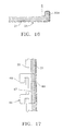
- FIG. 16 is an enlarged fragmentary sectional view which illustrates the corner defined between the center substrate part and the folded edge flange defining the frame, and specifically illustrates a variation wherein a mounting clip can have a part thereof clampingly held between the opposed beveled surfaces which are joined to define the corner of the pad internal support structure.
- FIG. 17 is a fragmentary elevational view taken generally along line 17 - 17 in FIG. 16 .
- FIG. 18 is an enlarged fragmentary elevational view showing one corner of the grooved side of the blank but illustrating a modified configuration of the V grooves formed therein, and
- FIG. 19 is a cross-sectional view taken generally along line 19 — 19 in FIG. 18 and illustrating the cross section of the modified V groove.
- FIGS. 1 and 2 there is illustrated part of an upright interior wall system 11 defined by a plurality of upright panels 12 which connect together horizontally in aligned and/or nonaligned relationship to define an upright wall for dividing interior spaces.
- Such wall systems 11 are conventionally utilized in offices and the like for dividing large interior spaces into smaller workspaces, and the wall system typically utilizes wall panels 12 which are either factory or on-site assembled, and are supported on a conventional floor and project upwardly to a desired height which, in most use situations, is less than ceiling height.
- the wall panel 12 as depicted in FIG. 2 includes one or more cover pads or tiles 13 which mount on one or both sides of an interior rigid frame 14 .
- the frame 14 conventionally includes a pair of parallel and sidewardly spaced elongate uprights or edge rails 15 which have the upper ends rigidly joined by a generally horizontally-extending top cross rail or beam 16 , with a further horizontally-extending bottom cross rail or beam 17 being joined between the uprights 15 adjacent the lower ends thereof.
- the uprights 15 and beams 16 - 17 hence define a rigid upright frame of rectangular configuration which is open in the interior thereof and which, in many applications, is provided with one or more intermediate horizontally-extending cross rails or beams 18 disposed in vertically spaced but parallel relationship between the beams 16 and 17 and extending between and rigidly joined to the uprights 15 .
- the cover tiles 13 are conventionally provided with some type of securing clip, such as the hooks 19 illustrated in FIG. 2 , which are releasably engageable with the frame for permitting the cover tiles to be attached to the exterior side surfaces of the frame.
- the uprights 15 are provided with a plurality of slots 28 positioned within a row extending vertically, i.e. longitudinally, along the upright for permitting the hooks 19 to be engaged therein.
- the frame also typically mounts adjustable feet or glides 29 , which can be mounted to the lower ends of the uprights 15 if desired, for supportive engagement with the floor.
- the overall panel system and more specifically the wall panel construction described above, is conventional and illustrates one of many conventional systems with respect to the manner of constructing the panel frame and the attachment of the cover pads thereto.
- FIGS. 3-10 there is illustrated an improved construction of a cover pad 21 according to the present invention.
- the cover pad 21 is intended for releasable securement to the sides of an upright wall panel frame, such as a frame similar to that illustrated by FIGS. 1 and 2 .
- the cover pad 21 in its assembled condition includes a generally ring-shaped edge frame 22 which is rigidly secured to and projects rearwardly from a main center pad part 23 which extends coextensively of the exterior side of the cover pad.
- the frame 22 and center pad part 23 define the internal support structure for the cover pad, which internal support structure is exteriorly covered by an outer covering 25 defined by a thin and flexible sheet of covering material typically a fabric (i.e. cloth) material.
- the rigid rectangular frame 22 is defined by generally parallel top and bottom edge members 32 and 33 respectively, which extend lengthwise throughout the length of the pad 21 and, at opposite ends, cooperate with the respectively adjacent ends of parallel side edge members 34 and 35 which extend vertically throughout the height of the pad member 21 in typically perpendicular relationship to the top and bottom edge members 32 - 33 .
- Each of the edge members 32 - 35 adjacent the front end thereof, defines thereon a tapered or beveled surface 36 which extends across the width of the edge member and which effectively abuts a respective corresponding opposed bevel surface 37 associated with the respective edge of the main center pad part 23 .
- opposed bevel surfaces 36 and 37 are compatible so as to effectively define a 90° angle between the edge members 32 - 36 and the main center panel part 23 , with the angle on the individual beveled surfaces 36 and 37 typically each being 45° relative to the substantially flat and planar front surface of the center pad part 23 .
- the opposed beveled surfaces 36 and 37 are typically fixedly secured together, such as by a suitable adhesive or glue or bonding agent being provided between the opposed engaging beveled surfaces.
- the upper and lower edge members 32 - 33 of the ringlike edge frame define thereon rear surfaces 38 which are substantially coplanar with rear surfaces 39 defined on the side edge members 34 - 35 .
- the plane defined by the rear surfaces 38 - 39 of the edge frame is generally parallel with but spaced rearwardly from the plane defined by the rear surface 41 of the main support pad 23 .
- the main support pad 23 defines thereon a generally planar front or exterior surface 42 which, at the peripheral edges thereof, defines right angle corners with respect to the side or exterior surfaces 43 defined by the edge members 32 - 35 . These side exterior surfaces 43 hence project rearwardly from the front surface 42 in generally perpendicular relationship thereto.
- the thin flexible outer covering material 25 for example a thin sheet of flexible fabric, includes a main or center fabric part 44 which extends coextensively over the front surface 42 of the center support pad 23 , with the fabric being wrapped around the outer corners of the center support pad so as to include side fabric portions 45 which cover the side exterior surfaces 43 of the ringlike edge frame.
- the flexible fabric sheet 25 is additionally preferably wrapped around the outer rear corner of the edge frame so as to have rear fabric portions 46 which typically at least partially cover the rear surfaces 38 - 39 of the edge frame, with the fabric sheet terminating in a free edge 47 .
- the fabric sheet is preferably fixedly secured to at least the edge frame, such as by being adhesively bonded or secured to at least the edge members 32 - 35 so as to maintain the center fabric part 44 stretched flatly (for example tautly) across the front surface 42 .
- the pad 21 of this invention possessing the above described constructional features is preferably manufactured utilizing a process similar or corresponding to the process as described below.
- a generally rigid support pad or blank 51 which has generally parallel and flat front and rear surfaces 48 and 49 , respectively, with the blank 51 typically being of a generally rectangular configuration defined by the edge walls 38 and 39 .
- the blank can be constructed of wood or other suitable materials, as explained hereinafter, so as to have a generally rigid construction, with the blank of desired dimensions being suitably initially formed, such as by being cut from larger sheets if necessary or desired.
- the support blank 51 is subjected to subsequent forming steps which include forming, for example cutting, a pair of generally parallel channel-like grooves 52 into the blank from the rear surface 49 thereof.
- the grooves 52 are respectively disposed adjacent but spaced inwardly in parallel relationship from the adjacent side edges 38 , and the grooves 52 extend longitudinally throughout the length of the blank.
- a further pair of generally parallel channel-like grooves 53 are formed, for example cut, into the blank from the rear surface 49 thereof, which grooves 53 are disposed adjacent but spaced inwardly from the respective end edges 39 .
- the grooves 53 extend transversely across the width of the blank and hence intersect the grooves 52 .
- the grooves 52 and 53 preferably have identical cross sections and, in the illustrated arrangement, preferably comprise V-shaped grooves which extend through substantially the entire thickness of the blank 51 except that the depth of the grooves 52 and 53 is preferably slightly less than the blank thickness so that the bottom of each groove, as defined by the apex 54 thereof, which apex also defines the lengthwise-extending centerline of the groove, is spaced a small distance from the front surface 48 of the blank 51 so as to leave a thin bridge or section 55 of blank material.
- the blank 51 after forming of the grooves 52 and 53 therein, remains as an integral and monolithic one-piece flat pad or plate which defines the main center support pad 23 as well as the side edge members 32 - 35 , all formed and integrally joined in a generally flat condition as illustrated in FIG. 7 .
- the grooves 52 and 53 where they intersect result in formation of small generally rectangular corner parts 56 which, due to the presence of the bridge sections 55 , remain integrally and rigidly joined to the blank.
- corner parts 56 are ultimately removed and discarded, however, so as to leave generally rectangular recesses 57 associated with the corners of the blank.
- the corner parts 56 can be removed either before or after attachment of the fabric to the blank, as discussed below.
- the grooved one-piece flat blank is attached, preferably by adhesive or glue, to the sheet of flexible covering material 25 which is also typically precut so as to have a rectangular configuration which corresponds to but is preferably slightly larger than the rectangular configuration of the blank 51 .
- the exterior or front surface 48 of the blank 51 and specifically those portions of the surface 48 corresponding to the edge or frame strips 32 - 35 , are provided with adhesive or glue thereon, and then the grooved blank 51 and fabric sheet 25 are appropriately superimposed, with the sheet 25 being maintained in a flat and non-wrinkled condition so that the fabric sheet along a band which extends around the outer portion thereof becomes adhesively fixed to the outer surfaces of the edge strips 32 - 35 .
- edge surfaces 38 and 39 are also preferably provided with adhesive or glue thereon, and the edge portions of the fabric sheet are wrapped upwardly to overlap and be adhesively secured to the edge surfaces 38 and 39 .
- This latter step can be carried out automatically by suitable processing equipment, such as use of flexible membrane presses or the like, or can be carried out manually if desired.
- corner pieces 56 they can be removed prior to attachment of the fabric 25 to the blank 51 merely by breaking the corner pieces away from the blank due to flexing of the corner pieces, causing fracturing along the thin bridge sections 55 .
- the corner pieces 56 can remain attached to the blank 51 during the initial securement of the fabric to the exterior surfaces of the edge frame strips 32 - 35 , with the corner pieces 56 being fractured and removed prior to the edge portions of the fabric edges being wrapped upwardly and secured to the edge surfaces 38 and 39 .
- the opposed edge strips 32 - 33 and 34 - 35 are folded upwardly relative to the center pad part 23 so as to define a complete ring-shaped frame which is integrally joined to and extends around the periphery of the main pad part 23 .
- corner portions 58 of the fabric sheet are lifted upwardly, either manually or mechanically, prior to all of the edge strips 32 - 35 being folded upwardly to define the continuous ring-shaped rectangular frame, whereby the corner fabric portions 58 are effectively clamped between the opposed ends of the edge strips 32 - 35 at each corner of the frame and hence create a tuck or fold of material 59 which is retained inside the frame rearwardly of the main pad part 23 , substantially as illustrated in FIG. 10 .
- the opposed horizontal edge flanges 32 and 33 can be initially folded upwardly into transverse relationship with respect to the center pad part 23 , which upward folding will, depending upon the material selected for the blank 51 , cause the bridge sections 55 to either fracture or function as a living hinge, with the fabric 25 also functioning as a living hinge, whereby the opposed horizontal edge flanges 32 - 33 can be folded upwardly so that the opposed beveled surfaces 36 and 37 defining the grooves 52 hence effectively abut and become adhesively secured together.
- the fabric corner portions 58 are either manually or mechanically folded upwardly and inwardly accompanied by upward folding of the opposed vertical edge strips 34 - 35 , which latter folding of the edge strips 34 - 35 again causes the bridge sections 55 to either fracture or function as a living hinge, with the fabric also functioning as a living hinge for joining the bridge sections 34 - 35 to the main center part 23 .
- the upward folding of the edge sections 34 - 35 again causes the opposed groove surfaces 36 - 37 to come substantially into contact with one another and to be adhesively secured together.
- the upward closure of the edge strips 34 - 35 causes the fabric corner portions 58 to be clamped and hence trapped between the opposed beveled end surfaces 62 - 63 as defined at the opposed ends of each respectively adjacent pair of edge strips so that the excess corner fabric 58 is hence trapped and held internally behind the pad so that the finished exterior corner of the pad is entirely covered by fabric and has a neat appearance which is relatively free of wrinkles or bunching.
- the folding of the edge strips 32 - 35 may be in a sequential manner, or the edge strips may all be folded simultaneously, either being possible and acceptable, depending upon the selected forming process and specifically the types of fixtures and equipment utilized and the degree of selected automation associated therewith. To facilitate this process, it is contemplated that same can be carried out substantially entirely automatically utilizing appropriate fixturing and handling equipment, or the process may be carried out at least in part with manual assistance and manipulation provided in conjunction with appropriate fixtures.
- the main interior support 24 which defines both the main center pad part 23 and the surrounding ring-shaped edge frame 22 can hence all be formed by a single support pad or blank 51 which, due to provision of appropriate grooves such as grooves 52 and 53 formed inwardly from the rear side thereof, enables the fabric 25 to be secured to the opposite side of the blank, typically at least in the edge regions of the blank which define the edge members 32 - 35 prior to their being hinged into the transverse frame-defining position, whereby the blank and fabric hence can be adhesively secured together while each is maintained in a generally flat and one-piece condition to thus facilitate the securement of the fabric to the blank.
- the material defining the rigid blank 51 may be wood, for example particle board.
- Other alternative materials for the blank 51 include mineral board (for example Celotex) or low-density wood fiberboard such as Korlite. With the blank 51 made of these materials, the bridge sections 55 will typically fracture during folding of the edge members 32 - 35 into the frame-forming position so that the living hinge is hence defined principally by the fabric which attaches the edge members to the center pad 31 .
- R board As an alternate material for defining the blank 51 , same could be constructed of what is known as R board, the latter being a polyurethane foam sheet having relatively thin fiberglass layers defined on opposite surfaces of the polyurethane sheet.
- R board When using R board for the blank 51 , the grooves 52 and 53 will typically penetrate through one fiberglass surface layer and through the entire thickness of the polyurethane sheet, with the opposite fiberglass surface layer being utilized to define the bridge section 55 since the fiberglass surface layer will typically have a thickness of about 0.010 inch.
- the nongrooved fiberglass skin will typically not fracture but rather will function as a living hinge when the edge members 32 - 35 are folded into the frame-defining position.
- the one fiberglass surface surface layer i.e. skin
- the one fiberglass surface surface layer hence cooperates with the fabric to define a living hinge.
- bio-fiber or Agri-fiber boards involving fibers such as flax or jute fibers secured with a polymer binder.
- Such materials when in plate form can additionally be molded with heat so as to permit embossing of the plate, particularly on the exterior surface thereof, so as to provide for variable surface treatments and the like.
- the material defining the blank 51 will most typically have a thickness in the range of three-eighths to three-fourths inch, with a typical and preferred thickness being about one-half inch. However, with some of the materials used for defining the blank, such as a metal/plastic/metal sandwich, the thickness of the blank material may be as little as one-eighth inch.
- the fabric When securing the fabric to the grooved blank 51 , the fabric can be secured to the blank by means of adhesive which is applied over the entire exterior surface of the blank 51 , or alternatively the adhesive may be applied solely to the exterior surfaces of the edge members 32 - 35 .
- the fabric edges can be wrapped around and adhesively secured to the end surfaces 38 and 39 of the edge strips, it will be appreciated that securement of the fabric edges to the end surfaces 38 and 39 can also be carried out using other securement techniques such as staples or the like since this surface of the finished cover pad 21 faces the panel frame and hence is hidden when the cover pad is mounted on the panel frame.
- the adhesive securement of the fabric to the blank may make use of a meltable adhesive such as a hot melt applied initially to the back side of the fabric, prior to placement of the fabric on the blank 51 , with the fabric after placement on the blank 51 then being heated such as within a bag-type membrane press so as to effect melting of the adhesive and securement of the fabric to the blank.
- a meltable adhesive such as a hot melt applied initially to the back side of the fabric, prior to placement of the fabric on the blank 51 , with the fabric after placement on the blank 51 then being heated such as within a bag-type membrane press so as to effect melting of the adhesive and securement of the fabric to the blank.
- the same process steps can again be utilized, although the corner pieces of the blank will typically be removed from the blank prior to the fabric being adhesively secured to the exterior non-grooved surface of the blank.
- each edge flange 32 - 35 of the blank 51 is defined by two parallel grooves such as by the grooves 52 A- 52 B and 53 A- 53 B, which are laterally spaced a small distance apart.
- the two grooves hence divide each edge flange into an intermediate flange part such as 35 A and an outer flange part 35 B.
- Each of the grooves 53 A and 53 B is again basically a 90° V-groove which penetrates through substantially the entire thickness of the blank except for the small bridge section 55 , and in this variation the fabric 25 has the edge thereof terminating in engagement with the outer flange part 35 B since there is no need to wrap the fabric around the edge surface 39 .
- the edge flange 35 A is folded upwardly to effect severing of the bridge associated with the inner groove 53 A so that the intermediate flange part 35 A hence projects rearwardly and defines the outer edge of the frame and of the cover pad, and the outer flange part 35 B is additionally folded inwardly relative to intermediate flange part 35 A to effect severing of the bridge at the bottom of groove 53 B so that the flange part 35 B as illustrated in FIG. 13 hence projects inwardly so as to be positioned rearwardly with respect to the main center pad part 23 .
- Each of the grooves when in the folded position is provided with means for fixing the flanges in the folded position of FIG.
- This double-grooved edge flange hence permits creation of a structurally more-robust frame while at the same time permitting the frame to have minimal front-to-back thickness so as to provide a slim cover pad.
- FIGS. 14 and 15 illustrate a further variation wherein the edge flanges associated with the blank are again of a double-groove construction similar to that illustrated by FIGS. 11-13 .
- the two grooves as designated 53 C and 53 D are of smaller angular extent, such as each being a 45° included angle V-groove, so that when the intermediate and outer edge flange parts 35 C and 35 D, respectively, are folded into the frame defining position illustrated by FIG.
- the outer flange part 35 D projects rearwardly and defines the outer periphery of the rigid frame, whereas the intermediate flange part 35 C effectively joins at a 45° angle between the main pad part 23 and the outer flange part 35 D so that the resulting pad has an exterior beveled corner. This hence permits elimination of the sharp exterior corner, and permits the pad to provide a different appearance.
- the improved cover pad 21 of this invention can also be provided with mounting clips 66 ( FIGS. 16 and 17 ) associated therewith, which clips are secured between the opposed groove sidewalls during the folding of the edge flanges so as to protrude rearwardly from the cover pad for suitable engagement with the frame.
- a suitable clip 66 is illustrated in FIGS. 16-17 and includes a main flange 67 which projects rearwardly from the rear surface of the center pad part 23 and has suitable hooks 68 or other fastening structure associated therewith for engagement with appropriate slots or structures associated with the panel frame.
- the clip 66 additionally has a mounting flange 69 which protrudes at an angle relative to the flange 67 and is positionable in the groove so as to be fixedly clamped between the opposed beveled surfaces 36 and 37 when the appropriate edge flange, such as flange 35 , is folded and secured in the frame-defining position.
- One or more such clips 66 can be clamped in vertically spaced relationship along each of the vertical edge flanges 34 - 35 for engagement with slots associated with the frame uprights 15 , or alternatively such clips can be associated with the horizontal edge flanges 32 - 33 and can be provided with suitable hooks or the like for engagement with the horizontal beams associated with the panel frame.
- FIGS. 18-19 illustrate a preferred cross section of the V groove.
- the apex of the V groove, as illustrated in FIG. 19 rather than being sharp is instead provided with a narrow but generally flat wall or surface 71 which can be generally parallel with but spaced a small distance from the front surface of the blank so as to define the narrow bridge 55 therebetween.
- This configuration of the V groove is believed easier to manufacture due to the ease of maintaining the shape and sharpness of the tool used for forming the V groove.
- this configuration additionally provides a small clearance or gap between the opposed tapered end surfaces 62 - 63 when the adjacent vertical and horizontal flanges are folded into their frame-defining position, which small clearance or gap facilitates the passage of excess corner fabric therebetween when the corner fabric is tucked and clamped between the frame corner in the manner illustrated by FIG. 10 .
- cover pad 21 of this invention and the manufacturing process therefor is particularly desirable for cover pads employing a thin flexible covering sheet formed of fabric or cloth
- other thin sheetlike covering materials having at least limited flexibility or bendability can also be utilized to define cover pads in accordance with the present invention.
- other sheet materials which may be useable for defining cover pads according to the present invention include thin metal foils or thin high pressure laminates which can be bent to define corners, particularly when heated, although such laminates may be useable only when a more gradual or rounded corner is provided, such as the beveled corner illustrated in FIGS. 14-15 .
- the resulting pad possesses substantial strength and rigidity, and at the same time the material defining the substrate or blank can have at least some sound-absorbing properties so as to at least partially minimize either reflection or transmission of environmental noise, and at the same time permit for more efficient and time-saving attachment of the fabric to the substrate while additionally resulting in a fabric-covered pad having improved uniformity of appearance and particularly improved formed fabric corners.
- the material defining the substrate of the pad namely the material defining the blank 51 , is also economical and hence further facilitates the efficient and economical manufacture of the cover pad.
- the blank can be directly formed as a flat sheetlike member wherein the grooves and the recessed corners are formed during formation of the blank.
- the blank may be die cut from a larger sheet of material so as to create the corner recesses during forming of the blank, prior to grooving thereof.
- the grooves in some situations they may be molded or pressed into the flat blank, particularly when the flat blank is initially formed so as to have the desired configuration suitable to permit folding of the edges.
- the substrate defining the blank may include therein binding fibers that act like an adhesive for adhering fabric to the face of the blank, thereby eliminating the need for a secondary operation of applying a separate adhesive to the board prior to securement of the fabric or covering.
- small electrical wires can be disposed within the grooves, such as in undercuts therein, whereby the wires will be trapped in and extend lengthwise along the grooves when the edge parts are in the assembled folded position, thereby enabling electrical wires to be more readily associated with the wall panel so as to extend lengthwise along the cover pads, with the wires of longitudinally adjacent cover pads being electrically adjoined on the inner sides of the cover pads by a suitable electrical jumper which can be provided with suitable releasable connectors for engagement with similar connectors formed inside the cover pads. If necessary or desirable, a part of the folded edge of the cover pad, such as the upright folded edges, can be partially removed to permit passage of electrical wires between and behind adjacent covers.
- the folded edge parts in the folded position can be disposed for fixed securement with the frame so as to hold the cover pad thereto, without effecting adhesive securement of the edge parts in the folded position.
- the grooves formed in the blank material will not penetrate entirely through the thickness of the blank, nevertheless in some situations the latter may be desirable. If the groove is permitted to penetrate entirely through the thickness of the blank, however, then in such situation the fabric will typically be adhered to the exterior side of the blank prior to forming of the entire groove therein, such that, when the groove is formed through the thickness of the blank, the fabric functions as a living hinge for positionally holding the center and edge frame parts together.
- cover or wall pad such as for use in defining an exterior surface of an upright wall, such as a portable wall panel
- the formed pad or product of the present invention can also be formed for other uses, including uses wherein the resulting wall pad may be oriented in a disposition other than vertical.
Landscapes
- Engineering & Computer Science (AREA)
- Architecture (AREA)
- Physics & Mathematics (AREA)
- Electromagnetism (AREA)
- Civil Engineering (AREA)
- Structural Engineering (AREA)
- Laminated Bodies (AREA)
Abstract
Description
-
- 1. cutting the blank 51 from a larger sheet of material;
- 2. forming transverse and longitudinal grooves in the rear surface of the blank through substantially the full thickness of the blank except for a small bridge thickness, such as a thickness in the neighborhood of about 0.010 inch;
- 3. positioning the fabric over and adhesively securing the fabric to the exterior non-grooved surface of the blank, at least along the exterior surfaces of the edge members;
- 4. wrapping the fabric edges around the edges of the blank and securing the fabric to the blank edges, either adhesively or mechanically;
- 5. removing the corner pieces from the blank (if not already done during the blank forming step) so as to leave corner recesses which have fabric corner portions extending thereover;
- 6. folding the edge members of the blank inwardly into the frame-defining position and folding the fabric corner portions inwardly between the adjacent ends of the edge members to effect clamping of the fabric corners between the ends of the edge member;
- 7. inserting mounting clips, if used, between the opposed beveled surfaces defined between the edge members and the center pad part; and
- 8. securing the edge members in the folded position relative to the center pad part, either adhesively (for example a hot melt) or mechanically (for example staples or nails) to define a closed ringlike frame in surrounding relationship to the center pad part.
Claims (18)
Priority Applications (2)
| Application Number | Priority Date | Filing Date | Title |
|---|---|---|---|
| US10/267,392 US6951592B2 (en) | 2002-10-09 | 2002-10-09 | Method of forming a fabric covered pad for wall panel |
| US11/105,636 US7614196B2 (en) | 2002-10-09 | 2005-04-14 | Pad for wall panel and forming process |
Applications Claiming Priority (1)
| Application Number | Priority Date | Filing Date | Title |
|---|---|---|---|
| US10/267,392 US6951592B2 (en) | 2002-10-09 | 2002-10-09 | Method of forming a fabric covered pad for wall panel |
Related Child Applications (1)
| Application Number | Title | Priority Date | Filing Date |
|---|---|---|---|
| US11/105,636 Continuation-In-Part US7614196B2 (en) | 2002-10-09 | 2005-04-14 | Pad for wall panel and forming process |
Publications (2)
| Publication Number | Publication Date |
|---|---|
| US20040071933A1 US20040071933A1 (en) | 2004-04-15 |
| US6951592B2 true US6951592B2 (en) | 2005-10-04 |
Family
ID=32068377
Family Applications (1)
| Application Number | Title | Priority Date | Filing Date |
|---|---|---|---|
| US10/267,392 Expired - Lifetime US6951592B2 (en) | 2002-10-09 | 2002-10-09 | Method of forming a fabric covered pad for wall panel |
Country Status (1)
| Country | Link |
|---|---|
| US (1) | US6951592B2 (en) |
Cited By (6)
| Publication number | Priority date | Publication date | Assignee | Title |
|---|---|---|---|---|
| US20050193666A1 (en) * | 2002-10-09 | 2005-09-08 | Haworth, Inc. | Pad for wall panel and forming process |
| US20090029338A1 (en) * | 2007-07-24 | 2009-01-29 | Acco Brands Usa Llc | Display board assembly |
| US20100193493A1 (en) * | 2007-10-26 | 2010-08-05 | Wing Yiu Yeung | Electrically heated towel rack |
| US20100272513A1 (en) * | 2009-04-22 | 2010-10-28 | Courtney William J | Method of manufacturing a tubing for a subsurface water drainage system |
| US8282760B2 (en) | 2010-06-10 | 2012-10-09 | Haworth, Inc. | Apparatus and process for wrapping and securing edge flaps of flexible cover sheet to panel structure |
| US8510953B2 (en) | 2011-05-11 | 2013-08-20 | Haworth, Inc. | Method for wrapping a flexible cover sheet on a panel |
Families Citing this family (7)
| Publication number | Priority date | Publication date | Assignee | Title |
|---|---|---|---|---|
| BE1017324A6 (en) * | 2006-09-25 | 2008-06-03 | M T F Metaalindustrie Nv | IMPROVED DEVICE FOR BUILDING WALLS, RACKS AND THE LIKE. |
| KR100949279B1 (en) | 2009-11-25 | 2010-03-25 | 김원태 | The apparatus and method of manufcature a led signboard |
| EP3527432B1 (en) * | 2018-02-20 | 2021-11-10 | Motherson Innovations Company Limited | Lining component for lining an interior of a passenger transport means and method for the production of such a lining component |
| EP3999696B1 (en) * | 2019-07-17 | 2025-05-21 | Saint-Gobain Placo | Interlocking gypsum building surface products, methods of manufacture |
| US11851874B2 (en) | 2019-07-17 | 2023-12-26 | Certainteed Gypsum, Inc. | Interlocking gypsum building surface products, methods of manufacture, and interlocking gypsum building surface systems |
| CA3192146A1 (en) | 2020-08-27 | 2022-03-03 | Timothy BRIGGS | Building surface product including attachment clip, building surface system, and method of manufacture |
| EP4483021A1 (en) | 2022-02-23 | 2025-01-01 | Certainteed Gypsum, Inc. | Building surface system including vertical rails, and method of assembly |
Citations (18)
| Publication number | Priority date | Publication date | Assignee | Title |
|---|---|---|---|---|
| US1836354A (en) | 1930-06-28 | 1931-12-15 | Jack B Abrams | Method of making metallic frames |
| US2149882A (en) * | 1937-03-01 | 1939-03-07 | Allegheny Ludlum Steel | Method of making a flanged panel |
| US2485648A (en) * | 1944-10-03 | 1949-10-25 | Glenn H Norquist | Method of making metal-clad panels |
| US3075862A (en) * | 1956-09-25 | 1963-01-29 | Volkswagenwerk Ag | Cover panels and method of manufacture |
| US3517427A (en) * | 1968-09-09 | 1970-06-30 | Winnebago Ind Inc | Method of making a multisided structure |
| US3885008A (en) | 1969-11-26 | 1975-05-20 | Robert E Martin | Method for producing prefabricated wall section with molded panels |
| US4000594A (en) | 1975-01-13 | 1977-01-04 | Kirk Jr James D | Building construction member |
| US4729917A (en) | 1986-10-24 | 1988-03-08 | Sackner Products Inc. | Method and laminate for thermoforming automobile headliners and like three dimensional objects |
| US5111579A (en) | 1989-12-14 | 1992-05-12 | Steelcase Inc. | Method for making a frameless acoustic cover panel |
| US5129202A (en) | 1990-02-23 | 1992-07-14 | Herman Miller, Inc. | Fabric tile construction |
| US5172530A (en) | 1990-11-06 | 1992-12-22 | Allsteel Inc. | Sound attenuation panel arrangement with cabling accommodating capability for office furniture space divider systems |
| US5174086A (en) | 1990-02-23 | 1992-12-29 | Herman Miller, Inc. | Method for making a fabric file construction |
| US5423151A (en) | 1991-09-13 | 1995-06-13 | Herman Miller, Inc. | Tackable tile |
| US5809715A (en) | 1995-11-15 | 1998-09-22 | Kokuyo Co., Ltd. | Panel |
| US6214148B1 (en) | 1997-02-12 | 2001-04-10 | David A. Hill | System for applying a wood veneer across a corner of an elongate core |
| US6223485B1 (en) | 1996-06-07 | 2001-05-01 | Herman Miller, Inc. | Wall panel system |
| US6226849B1 (en) | 1996-06-07 | 2001-05-08 | Herman Miller, Inc. | Method for making a frame member for a wall panel |
| US6256941B1 (en) | 1999-06-04 | 2001-07-10 | Haworth, Inc. | Pad for panel |
-
2002
- 2002-10-09 US US10/267,392 patent/US6951592B2/en not_active Expired - Lifetime
Patent Citations (18)
| Publication number | Priority date | Publication date | Assignee | Title |
|---|---|---|---|---|
| US1836354A (en) | 1930-06-28 | 1931-12-15 | Jack B Abrams | Method of making metallic frames |
| US2149882A (en) * | 1937-03-01 | 1939-03-07 | Allegheny Ludlum Steel | Method of making a flanged panel |
| US2485648A (en) * | 1944-10-03 | 1949-10-25 | Glenn H Norquist | Method of making metal-clad panels |
| US3075862A (en) * | 1956-09-25 | 1963-01-29 | Volkswagenwerk Ag | Cover panels and method of manufacture |
| US3517427A (en) * | 1968-09-09 | 1970-06-30 | Winnebago Ind Inc | Method of making a multisided structure |
| US3885008A (en) | 1969-11-26 | 1975-05-20 | Robert E Martin | Method for producing prefabricated wall section with molded panels |
| US4000594A (en) | 1975-01-13 | 1977-01-04 | Kirk Jr James D | Building construction member |
| US4729917A (en) | 1986-10-24 | 1988-03-08 | Sackner Products Inc. | Method and laminate for thermoforming automobile headliners and like three dimensional objects |
| US5111579A (en) | 1989-12-14 | 1992-05-12 | Steelcase Inc. | Method for making a frameless acoustic cover panel |
| US5129202A (en) | 1990-02-23 | 1992-07-14 | Herman Miller, Inc. | Fabric tile construction |
| US5174086A (en) | 1990-02-23 | 1992-12-29 | Herman Miller, Inc. | Method for making a fabric file construction |
| US5172530A (en) | 1990-11-06 | 1992-12-22 | Allsteel Inc. | Sound attenuation panel arrangement with cabling accommodating capability for office furniture space divider systems |
| US5423151A (en) | 1991-09-13 | 1995-06-13 | Herman Miller, Inc. | Tackable tile |
| US5809715A (en) | 1995-11-15 | 1998-09-22 | Kokuyo Co., Ltd. | Panel |
| US6223485B1 (en) | 1996-06-07 | 2001-05-01 | Herman Miller, Inc. | Wall panel system |
| US6226849B1 (en) | 1996-06-07 | 2001-05-08 | Herman Miller, Inc. | Method for making a frame member for a wall panel |
| US6214148B1 (en) | 1997-02-12 | 2001-04-10 | David A. Hill | System for applying a wood veneer across a corner of an elongate core |
| US6256941B1 (en) | 1999-06-04 | 2001-07-10 | Haworth, Inc. | Pad for panel |
Non-Patent Citations (12)
| Title |
|---|
| Auto 'V' grooving Inc., Automatic Line, www.vgrooving.com/automati.htm, 4 pages, Oct. 30, 2001. |
| Auto 'V' grooving Inc., AVG-48-UMFT, www.vgrooving.com/avg-48-m.htm, 3 pages, Oct. 30, 2001. |
| Auto 'V' grooving Inc., Cross 'V', www.vgrooving.com/cross.htm, 4 pages, Oct. 30, 2001. |
| Auto 'V' grooving Inc., Fold/Glue, www.vgrooving.com/Fold/glue.htm, 3 pages, Oct. 30, 2001. |
| Auto 'V' grooving Inc., High Volume www.vgrooving.com/prod03.htm, 2 pages, Oct. 30, 2001. |
| Auto 'V' grooving Inc., Home Page, www.vgrooving.com, 3 pages Oct. 30, 2001. |
| Auto 'V' grooving Inc., LG-1-SS, www.vgrooving.com/lg-1-ss.htm, 3 pages, Oct. 30, 2001. |
| Auto 'V' grooving Inc., LG-2-SS, www.vgrooving.com/lg-2-ss.htm, 3 pages, Oct. 30, 2001. |
| Auto 'V' grooving Inc., Lineal 'V', www.vgrooving.com/lineal.htm, 3 pages, Oct. 30, 2001. |
| Auto 'V' grooving Inc., Solid Surface, www.vgrooving.com/prod01.htm, 3 pages, Oct. 30, 2001. |
| Auto 'V' grooving Inc., 'V' Groovers, www.vgrooving.com/products.htm, 3 pages, Oct. 30, 2001. |
| Auto 'V' grooving Inc., Wood/Panel, www.vgrooving.com/prod02.htm, 5 pages, Oct. 30, 2001. |
Cited By (9)
| Publication number | Priority date | Publication date | Assignee | Title |
|---|---|---|---|---|
| US20050193666A1 (en) * | 2002-10-09 | 2005-09-08 | Haworth, Inc. | Pad for wall panel and forming process |
| US7614196B2 (en) * | 2002-10-09 | 2009-11-10 | Haworth, Inc. | Pad for wall panel and forming process |
| US20090029338A1 (en) * | 2007-07-24 | 2009-01-29 | Acco Brands Usa Llc | Display board assembly |
| US20100193493A1 (en) * | 2007-10-26 | 2010-08-05 | Wing Yiu Yeung | Electrically heated towel rack |
| US8334480B2 (en) * | 2007-10-26 | 2012-12-18 | Advanced Materials Enterprises Company Limited | Electrically heated towel rack |
| US20100272513A1 (en) * | 2009-04-22 | 2010-10-28 | Courtney William J | Method of manufacturing a tubing for a subsurface water drainage system |
| US8518201B2 (en) * | 2009-04-22 | 2013-08-27 | Midwest Diversified Technologies, Inc. | Method of manufacturing a tubing for a subsurface water drainage system |
| US8282760B2 (en) | 2010-06-10 | 2012-10-09 | Haworth, Inc. | Apparatus and process for wrapping and securing edge flaps of flexible cover sheet to panel structure |
| US8510953B2 (en) | 2011-05-11 | 2013-08-20 | Haworth, Inc. | Method for wrapping a flexible cover sheet on a panel |
Also Published As
| Publication number | Publication date |
|---|---|
| US20040071933A1 (en) | 2004-04-15 |
Similar Documents
| Publication | Publication Date | Title |
|---|---|---|
| US7614196B2 (en) | Pad for wall panel and forming process | |
| US6951592B2 (en) | Method of forming a fabric covered pad for wall panel | |
| US6339907B1 (en) | System of wall panels | |
| CA2072005C (en) | Predecorated wallboard joint and method of joining predecorated wallboards to form a concealed joint | |
| US5214892A (en) | Molding strip for mounting a flexible covering onto a support surface | |
| CN100420554C (en) | Veneered raised panel element and method of making same | |
| EP0993531B1 (en) | Fabric treatment and method for making the same | |
| US5715638A (en) | Fabric wall panel system | |
| US10202799B2 (en) | Double backbone core for automated door assembly line, door comprising same and method of using same | |
| US6132836A (en) | Corrugated structural paper fillers for the interior areas of hollow doors and the method of making same | |
| EP0172022A2 (en) | Improvements in or relating to panels | |
| US7225852B2 (en) | Covered pad for wall panel and manufacturing process | |
| CA2486826A1 (en) | Method of forming a glazed door, and glazed door | |
| US20060048659A1 (en) | Covering for architectural surfaces and method of forming and applying same | |
| AU2015101935A4 (en) | Improved composite panel | |
| JPH04228763A (en) | Fancy panel for use in ceiling or the like | |
| JP4493822B2 (en) | Manufacturing method of interior materials using bamboo | |
| US6399172B1 (en) | Hinged panel for furniture | |
| JP4584509B2 (en) | Waterproof structure around the opening and molded sheet for waterproofing | |
| CN218206414U (en) | Novel rock plate door plate | |
| CN215564078U (en) | A kind of assembled wall honeycomb panel edge closing structure | |
| JPH0223475Y2 (en) | ||
| JPH0421926Y2 (en) | ||
| JPH04336160A (en) | Floor construction method | |
| MXPA99011943A (en) | Moulded fabric covers |
Legal Events
| Date | Code | Title | Description |
|---|---|---|---|
| AS | Assignment |
Owner name: HAWORTH, INC., MICHIGAN Free format text: ASSIGNMENT OF ASSIGNORS INTEREST;ASSIGNORS:MCCONNELL, ANTHONY;WOELLPER, RANDOLPH;REEL/FRAME:013378/0050 Effective date: 20020828 |
|
| STCF | Information on status: patent grant |
Free format text: PATENTED CASE |
|
| FPAY | Fee payment |
Year of fee payment: 4 |
|
| FEPP | Fee payment procedure |
Free format text: PAYOR NUMBER ASSIGNED (ORIGINAL EVENT CODE: ASPN); ENTITY STATUS OF PATENT OWNER: LARGE ENTITY |
|
| FPAY | Fee payment |
Year of fee payment: 8 |
|
| SULP | Surcharge for late payment |
Year of fee payment: 7 |
|
| AS | Assignment |
Owner name: PNC BANK, NATIONAL ASSOCIATION, AS ADMINISTRATIVE Free format text: COLLATERAL ASSIGNMENT OF PATENTS;ASSIGNOR:HAWORTH, INC., HAWORTH, LTD. AND SUCCESSORS;REEL/FRAME:032606/0875 Effective date: 20140403 |
|
| FPAY | Fee payment |
Year of fee payment: 12 |
|
| AS | Assignment |
Owner name: HAWORTH, LTD., MICHIGAN Free format text: RELEASE BY SECURED PARTY;ASSIGNOR:PNC BANK, NATIONAL ASSOCIATION;REEL/FRAME:052788/0497 Effective date: 20200528 Owner name: HAWORTH, INC., MICHIGAN Free format text: RELEASE BY SECURED PARTY;ASSIGNOR:PNC BANK, NATIONAL ASSOCIATION;REEL/FRAME:052788/0497 Effective date: 20200528 |
|
| AS | Assignment |
Owner name: PNC BANK, PENNSYLVANIA Free format text: COLLATERAL ASSIGNMENT OF PATENTS;ASSIGNORS:HAWORTH, INC.;AFFORDABLE INTERIOR SYSTEMS, INC.;REEL/FRAME:062078/0770 Effective date: 20221129 |