US6935848B2 - Discharge muffler placement in a compressor - Google Patents
Discharge muffler placement in a compressor Download PDFInfo
- Publication number
- US6935848B2 US6935848B2 US10/441,306 US44130603A US6935848B2 US 6935848 B2 US6935848 B2 US 6935848B2 US 44130603 A US44130603 A US 44130603A US 6935848 B2 US6935848 B2 US 6935848B2
- Authority
- US
- United States
- Prior art keywords
- muffler
- compressor
- expansion
- predetermined distance
- housing
- Prior art date
- Legal status (The legal status is an assumption and is not a legal conclusion. Google has not performed a legal analysis and makes no representation as to the accuracy of the status listed.)
- Expired - Fee Related, expires
Links
Images


Classifications
-
- F—MECHANICAL ENGINEERING; LIGHTING; HEATING; WEAPONS; BLASTING
- F04—POSITIVE - DISPLACEMENT MACHINES FOR LIQUIDS; PUMPS FOR LIQUIDS OR ELASTIC FLUIDS
- F04B—POSITIVE-DISPLACEMENT MACHINES FOR LIQUIDS; PUMPS
- F04B49/00—Control, e.g. of pump delivery, or pump pressure of, or safety measures for, machines, pumps, or pumping installations, not otherwise provided for, or of interest apart from, groups F04B1/00 - F04B47/00
- F04B49/10—Other safety measures
-
- F—MECHANICAL ENGINEERING; LIGHTING; HEATING; WEAPONS; BLASTING
- F04—POSITIVE - DISPLACEMENT MACHINES FOR LIQUIDS; PUMPS FOR LIQUIDS OR ELASTIC FLUIDS
- F04B—POSITIVE-DISPLACEMENT MACHINES FOR LIQUIDS; PUMPS
- F04B39/00—Component parts, details, or accessories, of pumps or pumping systems specially adapted for elastic fluids, not otherwise provided for in, or of interest apart from, groups F04B25/00 - F04B37/00
- F04B39/0027—Pulsation and noise damping means
- F04B39/0055—Pulsation and noise damping means with a special shape of fluid passage, e.g. bends, throttles, diameter changes, pipes
- F04B39/0061—Pulsation and noise damping means with a special shape of fluid passage, e.g. bends, throttles, diameter changes, pipes using muffler volumes
-
- F—MECHANICAL ENGINEERING; LIGHTING; HEATING; WEAPONS; BLASTING
- F04—POSITIVE - DISPLACEMENT MACHINES FOR LIQUIDS; PUMPS FOR LIQUIDS OR ELASTIC FLUIDS
- F04B—POSITIVE-DISPLACEMENT MACHINES FOR LIQUIDS; PUMPS
- F04B39/00—Component parts, details, or accessories, of pumps or pumping systems specially adapted for elastic fluids, not otherwise provided for in, or of interest apart from, groups F04B25/00 - F04B37/00
- F04B39/12—Casings; Cylinders; Cylinder heads; Fluid connections
- F04B39/123—Fluid connections
-
- F—MECHANICAL ENGINEERING; LIGHTING; HEATING; WEAPONS; BLASTING
- F04—POSITIVE - DISPLACEMENT MACHINES FOR LIQUIDS; PUMPS FOR LIQUIDS OR ELASTIC FLUIDS
- F04B—POSITIVE-DISPLACEMENT MACHINES FOR LIQUIDS; PUMPS
- F04B49/00—Control, e.g. of pump delivery, or pump pressure of, or safety measures for, machines, pumps, or pumping installations, not otherwise provided for, or of interest apart from, groups F04B1/00 - F04B47/00
- F04B49/02—Stopping, starting, unloading or idling control
- F04B49/03—Stopping, starting, unloading or idling control by means of valves
-
- Y—GENERAL TAGGING OF NEW TECHNOLOGICAL DEVELOPMENTS; GENERAL TAGGING OF CROSS-SECTIONAL TECHNOLOGIES SPANNING OVER SEVERAL SECTIONS OF THE IPC; TECHNICAL SUBJECTS COVERED BY FORMER USPC CROSS-REFERENCE ART COLLECTIONS [XRACs] AND DIGESTS
- Y10—TECHNICAL SUBJECTS COVERED BY FORMER USPC
- Y10S—TECHNICAL SUBJECTS COVERED BY FORMER USPC CROSS-REFERENCE ART COLLECTIONS [XRACs] AND DIGESTS
- Y10S181/00—Acoustics
- Y10S181/403—Refrigerator compresssor muffler
-
- Y—GENERAL TAGGING OF NEW TECHNOLOGICAL DEVELOPMENTS; GENERAL TAGGING OF CROSS-SECTIONAL TECHNOLOGIES SPANNING OVER SEVERAL SECTIONS OF THE IPC; TECHNICAL SUBJECTS COVERED BY FORMER USPC CROSS-REFERENCE ART COLLECTIONS [XRACs] AND DIGESTS
- Y10—TECHNICAL SUBJECTS COVERED BY FORMER USPC
- Y10S—TECHNICAL SUBJECTS COVERED BY FORMER USPC CROSS-REFERENCE ART COLLECTIONS [XRACs] AND DIGESTS
- Y10S417/00—Pumps
- Y10S417/902—Hermetically sealed motor pump unit
Definitions
- the compressor itself typically is a hermetically sealed device that has an intake port and a discharge port.
- the hermetically sealed device typically is a metallic shell that houses an electric motor and a mechanical means, such as pistons or other mechanical portion, for compressing gas.
- a mechanical means such as pistons or other mechanical portion
- the gas cavity enclosed by the housing serves as a reservoir of low-pressure gas to be drawn into the mechanical section of the compressor.
- the electric motor is connected to a power source that provides line power for operation.
- the motor in turn drives the means for compressing gas.
- Compressors are typically categorized by the means used to compress the gas.
- compressors using a scroll compression device to compress refrigerant gas are referred to as scroll compressors; compressors using a piston device to compress the refrigerant gas are referred to as reciprocating compressors; compressors using rotating screw devices to compress a refrigerant gas are known as screw compressors. While there are differences among the compressors as to how refrigerant gas is compressed, the basic principles of operation as set forth above are common among the compressors, i.e., gas is drawn in through the gas intake when the motor is energized, the gas is compressed in the mechanical portion of the compressor and the highly compressed gas is discharged through an outlet port.
- mufflers have been attempted to eliminate, reduce or otherwise attenuate pressure pulsation and compressor noise.
- mufflers are typically positioned inside the compressor housing on the discharge side of the cylinder head, also referred to as a discharge head. While a muffler having an expansion chamber located adjacent to the discharge head can prevent pressure pulsation from propagating downstream, it has been found that placement of an expansion chamber muffler adjacent the discharge head reduces operating efficiency of the compressor, while also increasing the overall size of the compressor.
- the present invention further relates to a compressor system including a housing having an exhaust port.
- a compression means is provided for compressing a refrigerant fluid, the compression means being disposed within the housing.
- the compression means has a discharge port for exhausting compressed refrigerant fluid from the compression means.
- An acoustic muffler is disposed within the housing and in fluid communication with the discharge port, and the acoustic muffler is in fluid communication with the exhaust port.
- An expansion muffler is disposed exterior the housing a predetermined distance from the exhaust port and in fluid communication with the exhaust port.
- An advantage of the present invention is the inclusion of an expansion chamber muffler exterior of the compressor housing for attenuating pressure pulses from reaching the condenser, reducing the overall size of the compressor housing, while not adversely affecting compressor operating efficiency.
- FIG. 1 is a cross-section of a refrigerant compressor that incorporates the muffler system of the present invention
- FIG. 2 is a partial elevation view of the acoustic muffler discharge tube of the present invention taken along line II—II from FIG. 1 ;
- FIG. 3 is a perspective view of a muffler of the present invention.
- FIG. 4 is a cross-section of the muffler being joined to the discharge tube of the present invention.
- FIG. 5 is a graph illustrating pressure pulsation reduction versus expansion chamber location from the discharge head
- FIG. 6 is a graph illustrating pressure fluctuation attenuation for a tuned side-branch muffler
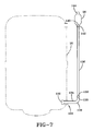
- FIG. 7 is an elevation view of an embodiment of the present invention showing the position of an external muffler.
- FIG. 8 is a cross section of the external muffler of the present invention.
- Compressor 2 includes an electrical motor 18 .
- a standard induction motor having a stator 20 and a rotor 22 is shown. However any other electrical motor may be used.
- a shaft assembly, 24 extends through rotor 22 .
- the bottom end 26 of shaft assembly 24 in this compressor 2 extends into a lubrication sump 28 and includes a series of apertures 27 .
- Connected to shaft assembly 24 below the motor is at least one piston assembly 30 .
- Compressor 2 of FIG. 1 depicts two piston assemblies.
- a connecting rod 32 is connected to a piston head 34 which moves back and forth within cylinder 36 .
- a cylinder head includes a gas inlet port 38 and a gas discharge port 40 . Associated with these ports 38 , 40 are respective suction valves and discharge valves (not shown) assembled in a manner well known in the art.
- Gas inlet port 38 is connected to an intake tube 54 which is in fluid communication with suction plenum 12 .
- Motor 18 is activated by a signal in response to a predetermined condition, for example, an electrical signal from a thermostat when a preset temperature is reached. Electricity is supplied to stator 20 , and the windings in the stator 20 cause rotor 22 to rotate. Rotation of rotor 22 causes the shaft assembly 24 to turn. In the compressor shown, oil in the sump 28 is drawn through apertures 27 in bottom end 26 of shaft 24 and moved upward through and along shaft 24 to lubricate the moving parts of compressor 2 .
- a predetermined condition for example, an electrical signal from a thermostat when a preset temperature is reached. Electricity is supplied to stator 20 , and the windings in the stator 20 cause rotor 22 to rotate. Rotation of rotor 22 causes the shaft assembly 24 to turn. In the compressor shown, oil in the sump 28 is drawn through apertures 27 in bottom end 26 of shaft 24 and moved upward through and along shaft 24 to lubricate the moving parts of compressor 2 .
- Rotation of rotor 22 also causes reciprocating motion of piston assembly 30 .
- piston head 34 moves away from gas inlet port 38
- the suction valve opens and refrigerant fluid is introduced into an expanding cylinder 36 volume.
- This gas is pulled from suction plenum 12 within compressor housing 16 .
- This gas is pulled into intake tube 54 to gas inlet port 38 where it passes through the suction valve and is introduced into cylinder 36 .
- piston assembly 30 reaches a first end (or top) of its stroke, shown by movement of piston head 34 to the right side of cylinder 36 of FIG. 1 , the suction valve closes.
- the piston head 34 then compresses the refrigerant gas by reducing the cylinder 36 volume.
- piston assembly 30 moves to a second end (or bottom) of its stroke, shown by movement of piston head 34 to the left side of cylinder 36 of FIG. 1 , a discharge valve is opened and the highly compressed refrigerant gas is expelled through gas discharge port 40 .
- the highly compressed refrigerant gas flows from the gas discharge port 40 into an acoustic muffler 50 then through an exhaust or discharge tube 52 , exiting the compressor housing 16 into a conduit connected to a condenser.
- An expansion chamber muffler 56 positioned outside the compressor housing 16 is connected in fluid communication with the conduit between the compressor 2 and the condenser adjacent the compressor housing 16 . This comprises one cycle of the piston assembly 30 .
- Acoustic muffler 50 additionally filters higher frequency pressure pulsations that tend to radiate directly from compressor housing 16 as unwanted noise.
- Acoustic muffler 50 preferably includes an internal pressure relief valve (IPRV), or pressure relief member 60 connected to a resonator volume 82 (FIG. 4 ).
- IPRV internal pressure relief valve
- FIG. 4 resonator volume 82
- acoustic muffler 50 preferably utilizes a side-branch resonator volume 82 to filter pressure pulsations that generate noise at the discharge tube 52 —compressor housing 16 penetration.
- Acoustic muffler 50 includes a tube 62 having opposed ends 76 , 78 .
- a threaded member 64 having a lip 80 at one end is positioned over end 78 of tube 62 for threadedly engaging the discharge head to maintain tube 62 in fluid communication with gas discharge port 40 .
- the end 78 of tube 62 and the end of threaded member 64 opposite lip 80 are substantially coincident to ensure the parts are sufficiently engaged therebetween.
- a housing 68 alternative includes opposed openings 70 , 72 which permits opening 70 of housing 68 to be positioned over end 78 of tube 62 until opening 72 of housing 68 sufficiently contacts lip 80 .
- Methods of securing tube 62 , housing 68 and threaded member 64 in position to each other such as spot welding, soldering, brazing, or by press-fit are well known in the art.
- Housing 68 is substantially cylindrical in profile and defines a resonator volume 82 between tube 62 and housing 68 .
- Tube 62 and housing 68 are maintained in fluid communication by a pair of preferably axially aligned resonator throats 66 formed in tube 62 .
- discharge tube 52 is connected to muffler 50 .
- the other end of discharge tube 52 is connected to the discharge outlet 15 of compressor 2 .
- discharge tube 52 may be segmented, such as to insert a discharge-side component such as an IPRV 60 .
- a portion of the discharge tube 52 adjacent muffler 50 preferably has a cane or inverted “J” shape, but can have any suitable shape. The shape of discharge tube 52 is primarily driven by the location and attitude of the two interface locations within the compressor housing 16 while maintaining sufficient spacing from compressor components.
- tube 62 of muffler 50 has an enlarged diameter portion 94 that extends into a shoulder 96 formed therein that is coincident with axis 84 .
- an end 98 of exhaust tube 52 is directed inside the enlarged diameter portion 94 of tube 62 past end 76 to the extent required to form the joint, up to “bottoming out” at the shoulder 96 .
- Discharge tube 52 connects in a similar way to discharge outlet 15 .
- Discharge outlet 15 includes a fitting 100 that extends through an aperture 112 in the compressor housing 16 .
- the fitting 100 is provided with a secure joint between itself and the compressor housing 16 that is both fluid tight and rigid, both to prevent the leakage of refrigerant through aperture 112 and avoid unnecessary flexure to the subsequent joints formed between both the fitting 100 and the discharge tube 52 inside the compressor housing 16 and between the conduit and the fitting 100 located outside the compressor housing 16 .
- a fitting portion 114 of fitting 100 extends inside the compressor housing 16 which axially aligns along axis 99 with end 106 of tube 52 .
- the portion of fitting portion 114 that is inside compressor housing 16 includes an end 102 having an enlarged diameter portion 104 .
- the end 106 of discharge tube 52 is directed past end 102 of fitting portion 114 along axis 99 into the enlarged diameter portion 104 until a joint is formed.
- the joint may be secured by soldering or other appropriate bonding method.
- the joints for each end 98 , 106 of discharge tube 52 is established prior to securing the joints.
- fitting 100 extends outside compressor housing 16 into an extension 134 which further extends into a bend 130 , preferably a right angle, that terminates at an upturned end 132 .
- fitting 100 could terminate immediately outside of compressor housing 16 , if desired.
- a substantially straight conduit 136 has an end 138 that inserts inside of end 132 of fitting 100 for connection therewith.
- Conduit 136 extends substantially parallel to the compressor housing 16 in a substantially vertical direction by virtue of the right angle connection with end 132 , terminating at end 140 which, in one embodiment, is adjacent the top of the compressor housing 16 .
- conduit 136 could be curved in shape and could extend in any direction or attitude with respect to fitting 100 .
- the second muffler member 56 is connected at inlet end 142 with end 140 of conduit 136 and has an opposed exhaust end 144 for connection with a conduit connecting with a condenser (not shown).
- Fitting 100 , conduit 136 and muffler 56 are in continuous fluid communication therebetween so that refrigerant fluid exhausting from compressor housing 16 sequentially flows through fitting 100 and conduit 136 before reaching muffler 56 .
- Muffler 56 attenuates pressure pulses generated by operation of the compressor.
- Muffler 56 is provided with the inlet end 142 and the exhaust end 144 on opposed ends of muffler 56 .
- a preferably enlarged diameter housing 152 is interposed between inlet end 142 and exhaust end 144 .
- the gas volume enclosed by housing 152 serves to filter pressure pulsations propagating in conduit 136 .
- the ability for muffler 56 to filter pressure pulsations is extremely sensitive to the total distance between the discharge head and muffler 56 .
- the muffler 56 can be located along the discharge path at numerous positions to filter a specific troublesome frequency.
- FIG. 5 provides a design guide to position the muffler such to achieve maximum reduction attenuation of the pulsation frequency, often the most troublesome frequency in a refrigerant compressor as will be discussed in additional detail below.
- a compressor system using the novel combination of the acoustic muffler 50 mounted internally within the compressor housing 16 and muffler 56 mounted adjacent but external to the compressor housing has been tested. Further referring to FIG. 5 , sound attenuation is illustrated as a function of distance from the discharge head of the compressor for a particular frequency and refrigerant. It is shown that significant sound attenuation can be achieved with an expansion chamber muffler positioned approximately 15-20 inches from the discharge head, which is identified as region “A” on the attenuation curve. The distance from the discharge head to the expansion chamber muffler is related to the travel distance of refrigerant between the discharge head and the expansion chamber muffler.
- Region “A” is inside the compressor housing which is identified by the vertical dotted line that is approximately 32 inches from the discharge head and additionally identified as “C”.
- significant efficiency losses of at least two percent are attributable with the muffler being located within the compressor housing adjacent the discharge head as compared to being located further downstream.
- the muffler requires significant volume which is not always available inside the housing. Note, however, that further along the curve, approximately 45-50 inches from the discharge head, identified as region “B”, the sound attenuation is substantially identical to the level shown in region “A”.
- region “D”, which is located approximately 77-82 inches from the discharge head provides substantially identical sound attenuation to the level shown in region “A”.
- Region “B” is located approximately 15-20 inches from the position of the housing penetration and region “D” is located approximately 45-50 inches from the housing penetration.
- the position of the compressor housing discharge port and the housing penetration (region “C”) are substantially the same.
- the compressor operates as quietly and more efficiently while gaining additional room within the compressor housing or permitting the volume of the compressor housing to be reduced and still achieving the same performance.
- the peak attenuation levels is not especially “pointed”. That is, at Region “B”, although maximum attenuation of approximately 15 dB may occur at 48 inches from the discharge head, due to the relative “flatness” of the curve along its peak, attenuation levels of approximately 14.5-15 dB may be achieved with a range of approximately 45-51 inches from the discharge head.
- the expansion muffler chamber within a reasonably broad distance range from the discharge head, without requiring precise measurements, it appears possible to achieve substantially maximum noise attenuation levels for the expansion muffler.
- muffler 56 In addition to reduced compressor housing size and efficiency gains as previously discussed, by virtue of muffler 56 being used outside the compressor housing, the user has the opportunity to easily replace muffler 56 , if desired. Typically, as compressor capacity increases, so does the amplitude of the pressure pulsations associated with its operation. Thus, different mufflers may be desirable for use with compressors having different operating capacities, although identical mufflers may be selected for use with compressors having different operating capacities to reduce inventory. With the present invention, if the user need only replace an existing muffler with another configured to attenuate the increased amplitudes, since the existing muffler was already positioned within the range of lengths corresponding to substantially maximum attenuation levels.
- the expansion muffler 56 functions to filter pressure pulses from propagating downstream that generate noise upon contacting valves or condenser coils
- a muffler is still needed inside the compressor housing to filter the pressure pulses that may transmit noise to the housing at the point of penetration.
- FIG. 6 the sound attenuating performance of the acoustic muffler is illustrated. As shown, peak attenuation occurs at approximately 1,000 Hz corresponding to an attenuation of approximately 32 dB which is sufficient to effectively address vibration issues within the compressor housing which are centered around this frequency range.
Landscapes
- Engineering & Computer Science (AREA)
- Mechanical Engineering (AREA)
- General Engineering & Computer Science (AREA)
- Compressor (AREA)
- Applications Or Details Of Rotary Compressors (AREA)
Abstract
Description
Claims (20)
Priority Applications (3)
| Application Number | Priority Date | Filing Date | Title |
|---|---|---|---|
| US10/441,306 US6935848B2 (en) | 2003-05-19 | 2003-05-19 | Discharge muffler placement in a compressor |
| PCT/US2004/014973 WO2004104495A2 (en) | 2003-05-19 | 2004-05-13 | Discharge muffler placement in a compressor |
| US11/189,527 US20050276711A1 (en) | 2003-05-19 | 2005-07-26 | Muffler system for a compressor |
Applications Claiming Priority (1)
| Application Number | Priority Date | Filing Date | Title |
|---|---|---|---|
| US10/441,306 US6935848B2 (en) | 2003-05-19 | 2003-05-19 | Discharge muffler placement in a compressor |
Related Child Applications (1)
| Application Number | Title | Priority Date | Filing Date |
|---|---|---|---|
| US11/189,527 Continuation-In-Part US20050276711A1 (en) | 2003-05-19 | 2005-07-26 | Muffler system for a compressor |
Publications (2)
| Publication Number | Publication Date |
|---|---|
| US20040234387A1 US20040234387A1 (en) | 2004-11-25 |
| US6935848B2 true US6935848B2 (en) | 2005-08-30 |
Family
ID=33449964
Family Applications (2)
| Application Number | Title | Priority Date | Filing Date |
|---|---|---|---|
| US10/441,306 Expired - Fee Related US6935848B2 (en) | 2003-05-19 | 2003-05-19 | Discharge muffler placement in a compressor |
| US11/189,527 Abandoned US20050276711A1 (en) | 2003-05-19 | 2005-07-26 | Muffler system for a compressor |
Family Applications After (1)
| Application Number | Title | Priority Date | Filing Date |
|---|---|---|---|
| US11/189,527 Abandoned US20050276711A1 (en) | 2003-05-19 | 2005-07-26 | Muffler system for a compressor |
Country Status (2)
| Country | Link |
|---|---|
| US (2) | US6935848B2 (en) |
| WO (1) | WO2004104495A2 (en) |
Cited By (10)
| Publication number | Priority date | Publication date | Assignee | Title |
|---|---|---|---|---|
| US20040223854A1 (en) * | 2000-12-01 | 2004-11-11 | Tomell Phillip A. | Reciprocating piston compressor having improved noise attenuation |
| US20060275150A1 (en) * | 2005-05-23 | 2006-12-07 | Bitzer Kuehlmaschinenbau Gmbh | Refrigerant compressor |
| US20070101706A1 (en) * | 2005-09-30 | 2007-05-10 | Harris Ralph E | Side branch absorber for exhaust manifold of two-stroke internal combustion engine |
| US7228935B2 (en) * | 2002-09-10 | 2007-06-12 | Andreas Stihl Ag & Co. Kg | Attachment pin for an exhaust-gas muffler |
| US20080253900A1 (en) * | 2007-04-11 | 2008-10-16 | Harris Ralph E | Gas compressor with pulsation absorber for reducing cylinder nozzle resonant pulsation |
| US7946382B2 (en) | 2006-05-23 | 2011-05-24 | Southwest Research Institute | Gas compressor with side branch absorber for pulsation control |
| US8123498B2 (en) | 2008-01-24 | 2012-02-28 | Southern Gas Association Gas Machinery Research Council | Tunable choke tube for pulsation control device used with gas compressor |
| WO2013097005A1 (en) | 2011-12-26 | 2013-07-04 | Whirlpool S.A. | Discharge line of compressor |
| US8827034B2 (en) | 2013-01-18 | 2014-09-09 | Halla Visteon Climate Control Corporation | Pressure pulsation dampening device |
| US11542933B2 (en) * | 2019-04-29 | 2023-01-03 | Gast Manufacturing, Inc. | Sound reduction device for rocking piston pumps and compressors |
Families Citing this family (16)
| Publication number | Priority date | Publication date | Assignee | Title |
|---|---|---|---|---|
| DE102006011577A1 (en) * | 2006-03-10 | 2007-09-13 | Linde Ag | Compressor system with a buffer tank |
| US9404499B2 (en) * | 2006-12-01 | 2016-08-02 | Emerson Climate Technologies, Inc. | Dual chamber discharge muffler |
| US8057194B2 (en) * | 2006-12-01 | 2011-11-15 | Emerson Climate Technologies, Inc. | Compressor with discharge muffler attachment using a spacer |
| US8740590B2 (en) * | 2007-12-17 | 2014-06-03 | Southern Gas Association Gas Machinery Research Council | Hyperbolic horn for pulsation filter device used with gas compressor |
| DE102009049988A1 (en) * | 2009-10-20 | 2011-04-21 | Linde Ag | compressor plant |
| US8740581B2 (en) * | 2010-03-30 | 2014-06-03 | Southern Gas Association Gas Machinery Research Council | Pressure recovery insert for reciprocating gas compressor |
| EP2619460A2 (en) * | 2010-09-21 | 2013-07-31 | Johnson Controls Technology Company | Manual selective attenuator |
| US9657732B2 (en) * | 2010-09-23 | 2017-05-23 | Ingersoll-Rand Company | Modular discharge silencer for vehicle-mounted compressor |
| USD658274S1 (en) * | 2010-12-03 | 2012-04-24 | Finish Thompson, Inc. | Discharge head |
| USD657849S1 (en) * | 2010-12-03 | 2012-04-17 | Finish Thompson, Inc. | Discharge head |
| USD658273S1 (en) * | 2010-12-03 | 2012-04-24 | Finish Thompson, Inc. | Discharge head |
| GB201402573D0 (en) * | 2014-02-13 | 2014-04-02 | J & E Hall Ltd | Discharge muffler |
| CZ308291B6 (en) * | 2014-04-10 | 2020-04-22 | Hanon Systems | Damping device and producing it |
| CN107461317B (en) * | 2017-08-16 | 2019-11-19 | 加西贝拉压缩机有限公司 | A kind of interior comb connection structure of compressor |
| WO2019100215A1 (en) * | 2017-11-21 | 2019-05-31 | 广东美的暖通设备有限公司 | Compressor assembly, air conditioner outdoor unit, and air conditioning system |
| US10539066B1 (en) * | 2018-11-21 | 2020-01-21 | GM Global Technology Operations LLC | Vehicle charge air cooler with an integrated resonator |
Citations (50)
| Publication number | Priority date | Publication date | Assignee | Title |
|---|---|---|---|---|
| US4033707A (en) | 1973-04-04 | 1977-07-05 | Atlas Industries, Inc. | Refrigeration compressor structures and their methods of construction |
| US4185715A (en) | 1978-05-30 | 1980-01-29 | Rudolph Reu Boiu | Sound-attenuating muffler for exhaust gases |
| GB2039613A (en) | 1979-01-13 | 1980-08-13 | Daimler Benz Ag | Silencing means for a compressor installation |
| US4239461A (en) | 1978-11-06 | 1980-12-16 | Copeland Corporation | Compressor induction system |
| US4313715A (en) | 1979-12-21 | 1982-02-02 | Tecumseh Products Company | Anti-slug suction muffler for hermetic refrigeration compressor |
| US4330239A (en) | 1979-10-10 | 1982-05-18 | Tecumseh Products Company | Compressor muffler |
| US4360321A (en) | 1980-05-20 | 1982-11-23 | General Motors Corporation | Multicylinder refrigerant compressor muffler arrangement |
| US4370099A (en) | 1977-11-14 | 1983-01-25 | Tecumseh Products Company | Discharge gas temperature control |
| US4396360A (en) | 1981-02-03 | 1983-08-02 | Copeland Corporation | Dual compressors |
| US4401418A (en) | 1981-04-29 | 1983-08-30 | White Consolidated Industries, Inc. | Muffler system for refrigeration compressor |
| US4406593A (en) | 1980-06-11 | 1983-09-27 | Tecumseh Products Company | Mounting spud arrangement for a hermetic compressor |
| US4406590A (en) | 1980-06-11 | 1983-09-27 | Tecumseh Products Company | Hermetic compressor |
| US4518323A (en) | 1983-07-25 | 1985-05-21 | Copeland Corporation | Hermetic refrigeration compressor |
| US4559686A (en) | 1980-06-11 | 1985-12-24 | Tecumseh Products Company | Method of assembling a hermetic compressor |
| US4573880A (en) * | 1982-09-02 | 1986-03-04 | Sanyo Electric Co., Ltd. | Hermetically sealed motor compressor |
| US4576555A (en) | 1984-11-13 | 1986-03-18 | Tecumseh Products Company | Oil dispersing device |
| US4591318A (en) | 1981-02-03 | 1986-05-27 | Copeland Corporation | Dual compressors |
| US4623304A (en) * | 1981-12-08 | 1986-11-18 | Sanyo Electric Co., Ltd. | Hermetically sealed rotary compressor |
| US4781545A (en) | 1985-09-30 | 1988-11-01 | Kabushiki Kaisha Toshiba | Rotary compressor with sound suppression tubular cavity section |
| US4929157A (en) | 1987-11-23 | 1990-05-29 | Ford Motor Company | Pulsation damper for air conditioning compressor |
| JPH039089A (en) | 1989-06-05 | 1991-01-16 | Sanyo Electric Co Ltd | Muffling device for compressor |
| US5101931A (en) | 1990-05-23 | 1992-04-07 | Copeland Corporation | Discharge muffler and method |
| US5112198A (en) | 1991-02-08 | 1992-05-12 | General Motors Corporation | Refrigerant compressor having variable restriction pressure pulsation attenuator |
| US5129793A (en) | 1990-10-24 | 1992-07-14 | Copeland Corporation | Suction muffler |
| US5194717A (en) | 1990-10-18 | 1993-03-16 | Tecumseh Products Company | Bracket for mounting a crankcase heater |
| US5205719A (en) | 1992-01-13 | 1993-04-27 | Copeland Corporation | Refrigerant compressor discharge muffler |
| US5224840A (en) | 1991-03-28 | 1993-07-06 | Tecumseh Products Company | Integral suction system |
| US5252036A (en) | 1990-06-19 | 1993-10-12 | Tecumseh Products Company | Normal direction heater for compressor crankcase heat |
| US5326231A (en) | 1993-02-12 | 1994-07-05 | Bristol Compressors | Gas compressor construction and assembly |
| US5330329A (en) | 1993-06-01 | 1994-07-19 | Copeland Corporation | Suction conduit assembly mounting |
| US5333460A (en) | 1992-12-21 | 1994-08-02 | Carrier Corporation | Compact and serviceable packaging of a self-contained cryocooler system |
| US5341654A (en) | 1993-04-16 | 1994-08-30 | Copeland Corporation | Suction gas conduit |
| US5427506A (en) | 1993-08-30 | 1995-06-27 | Tecumseh Products Company | Compressor pressure relief assembly |
| US5503542A (en) | 1995-01-13 | 1996-04-02 | Copeland Corporation | Compressor assembly with welded IPR valve |
| US5556265A (en) | 1994-10-05 | 1996-09-17 | Kabushiki Kaisha Toyoda Jidoshokki Seisakusho | Multi-piston type refrigerant compressor with means for damping suction and discharge gas pulsation |
| US5596879A (en) * | 1994-10-04 | 1997-01-28 | Carrier Corporation | Method for determining optimum placement of refrigerant line muffler |
| US5635687A (en) * | 1994-07-05 | 1997-06-03 | Necchi Compressori S.R.L. | Muffler for motor compressors for refrigeration appliances |
| US5800133A (en) | 1995-10-12 | 1998-09-01 | Kabushiki Kaisha Toyoda Jidoshokki Seisakusho | Compressor with discharge chamber relief valve |
| US5899670A (en) | 1996-07-08 | 1999-05-04 | Kabushiki Kaisha Toyoda Jidoshokki Seisakusho | Integrated muffler structure for compressors |
| US6102160A (en) | 1998-05-15 | 2000-08-15 | Copeland Corporation | Compressor lubrication |
| EP1033492A1 (en) | 1999-03-01 | 2000-09-06 | Kabushiki Kaisha Toyoda Jidoshokki Seisakusho | Compressor with suction muffler structure |
| US6149397A (en) | 1998-03-06 | 2000-11-21 | Toyoda Automatic Loom Works, Ltd. | Pressure pulsations reducing compressor |
| US6152703A (en) | 1996-06-14 | 2000-11-28 | Matsushita Refrigeration Company | Hermetic-type compressor |
| US6213732B1 (en) | 1997-08-28 | 2001-04-10 | Matsushita Electric Industrial Co., Ltd. | Rotary compressor |
| US6296457B1 (en) * | 1999-04-15 | 2001-10-02 | Kabushiki Kaisha Toyoda Jidoshokki | Discharge pulsation damping apparatus for compressor |
| US6305919B1 (en) | 1999-08-24 | 2001-10-23 | Visteon Global Technologies, Inc. | Hydraulic pump housing with an integral dampener chamber |
| US6332510B1 (en) | 1996-09-30 | 2001-12-25 | Silentor Holding A/S | Gas flow silencer |
| US6390788B1 (en) | 1998-12-31 | 2002-05-21 | Lg Electronics Inc. | Working-fluid intaking structure for hermetic compressor |
| US20020098093A1 (en) | 2000-12-01 | 2002-07-25 | Tomell Phillip A. | Reciprocating piston compressor having improved noise attenuation |
| US6488482B1 (en) | 2000-09-07 | 2002-12-03 | Donald Yannascoli | Integral compressor muffler |
Family Cites Families (1)
| Publication number | Priority date | Publication date | Assignee | Title |
|---|---|---|---|---|
| US5204709A (en) * | 1990-09-17 | 1993-04-20 | Olympus Optical Co., Ltd. | Camera apparatus having function for changing condition of release operation |
-
2003
- 2003-05-19 US US10/441,306 patent/US6935848B2/en not_active Expired - Fee Related
-
2004
- 2004-05-13 WO PCT/US2004/014973 patent/WO2004104495A2/en not_active Ceased
-
2005
- 2005-07-26 US US11/189,527 patent/US20050276711A1/en not_active Abandoned
Patent Citations (54)
| Publication number | Priority date | Publication date | Assignee | Title |
|---|---|---|---|---|
| US4033707A (en) | 1973-04-04 | 1977-07-05 | Atlas Industries, Inc. | Refrigeration compressor structures and their methods of construction |
| US4370099A (en) | 1977-11-14 | 1983-01-25 | Tecumseh Products Company | Discharge gas temperature control |
| US4185715A (en) | 1978-05-30 | 1980-01-29 | Rudolph Reu Boiu | Sound-attenuating muffler for exhaust gases |
| US4239461A (en) | 1978-11-06 | 1980-12-16 | Copeland Corporation | Compressor induction system |
| GB2039613A (en) | 1979-01-13 | 1980-08-13 | Daimler Benz Ag | Silencing means for a compressor installation |
| US4330239A (en) | 1979-10-10 | 1982-05-18 | Tecumseh Products Company | Compressor muffler |
| US4313715A (en) | 1979-12-21 | 1982-02-02 | Tecumseh Products Company | Anti-slug suction muffler for hermetic refrigeration compressor |
| US4360321A (en) | 1980-05-20 | 1982-11-23 | General Motors Corporation | Multicylinder refrigerant compressor muffler arrangement |
| US4559686A (en) | 1980-06-11 | 1985-12-24 | Tecumseh Products Company | Method of assembling a hermetic compressor |
| US4406590B1 (en) | 1980-06-11 | 1985-11-12 | ||
| US4406593A (en) | 1980-06-11 | 1983-09-27 | Tecumseh Products Company | Mounting spud arrangement for a hermetic compressor |
| US4406590A (en) | 1980-06-11 | 1983-09-27 | Tecumseh Products Company | Hermetic compressor |
| US4591318A (en) | 1981-02-03 | 1986-05-27 | Copeland Corporation | Dual compressors |
| US4396360A (en) | 1981-02-03 | 1983-08-02 | Copeland Corporation | Dual compressors |
| US4401418B1 (en) | 1981-04-29 | 1998-01-06 | White Consolidated Ind Inc | Muffler system for refrigeration compressor |
| US4401418A (en) | 1981-04-29 | 1983-08-30 | White Consolidated Industries, Inc. | Muffler system for refrigeration compressor |
| US4623304A (en) * | 1981-12-08 | 1986-11-18 | Sanyo Electric Co., Ltd. | Hermetically sealed rotary compressor |
| US4573880A (en) * | 1982-09-02 | 1986-03-04 | Sanyo Electric Co., Ltd. | Hermetically sealed motor compressor |
| US4518323A (en) | 1983-07-25 | 1985-05-21 | Copeland Corporation | Hermetic refrigeration compressor |
| US4576555A (en) | 1984-11-13 | 1986-03-18 | Tecumseh Products Company | Oil dispersing device |
| US4781545A (en) | 1985-09-30 | 1988-11-01 | Kabushiki Kaisha Toshiba | Rotary compressor with sound suppression tubular cavity section |
| US4929157A (en) | 1987-11-23 | 1990-05-29 | Ford Motor Company | Pulsation damper for air conditioning compressor |
| JPH039089A (en) | 1989-06-05 | 1991-01-16 | Sanyo Electric Co Ltd | Muffling device for compressor |
| US5101931A (en) | 1990-05-23 | 1992-04-07 | Copeland Corporation | Discharge muffler and method |
| US5252036A (en) | 1990-06-19 | 1993-10-12 | Tecumseh Products Company | Normal direction heater for compressor crankcase heat |
| US5194717A (en) | 1990-10-18 | 1993-03-16 | Tecumseh Products Company | Bracket for mounting a crankcase heater |
| US5129793A (en) | 1990-10-24 | 1992-07-14 | Copeland Corporation | Suction muffler |
| US5112198A (en) | 1991-02-08 | 1992-05-12 | General Motors Corporation | Refrigerant compressor having variable restriction pressure pulsation attenuator |
| US5224840A (en) | 1991-03-28 | 1993-07-06 | Tecumseh Products Company | Integral suction system |
| US5205719A (en) | 1992-01-13 | 1993-04-27 | Copeland Corporation | Refrigerant compressor discharge muffler |
| EP0551713A1 (en) | 1992-01-13 | 1993-07-21 | Copeland Corporation | Refrigerant compressor discharge muffler |
| US5333460A (en) | 1992-12-21 | 1994-08-02 | Carrier Corporation | Compact and serviceable packaging of a self-contained cryocooler system |
| US5326231A (en) | 1993-02-12 | 1994-07-05 | Bristol Compressors | Gas compressor construction and assembly |
| US5341654A (en) | 1993-04-16 | 1994-08-30 | Copeland Corporation | Suction gas conduit |
| US5330329A (en) | 1993-06-01 | 1994-07-19 | Copeland Corporation | Suction conduit assembly mounting |
| US5427506A (en) | 1993-08-30 | 1995-06-27 | Tecumseh Products Company | Compressor pressure relief assembly |
| US5635687A (en) * | 1994-07-05 | 1997-06-03 | Necchi Compressori S.R.L. | Muffler for motor compressors for refrigeration appliances |
| US5596879A (en) * | 1994-10-04 | 1997-01-28 | Carrier Corporation | Method for determining optimum placement of refrigerant line muffler |
| US5556265A (en) | 1994-10-05 | 1996-09-17 | Kabushiki Kaisha Toyoda Jidoshokki Seisakusho | Multi-piston type refrigerant compressor with means for damping suction and discharge gas pulsation |
| US5503542A (en) | 1995-01-13 | 1996-04-02 | Copeland Corporation | Compressor assembly with welded IPR valve |
| US5800133A (en) | 1995-10-12 | 1998-09-01 | Kabushiki Kaisha Toyoda Jidoshokki Seisakusho | Compressor with discharge chamber relief valve |
| US6152703A (en) | 1996-06-14 | 2000-11-28 | Matsushita Refrigeration Company | Hermetic-type compressor |
| US5899670A (en) | 1996-07-08 | 1999-05-04 | Kabushiki Kaisha Toyoda Jidoshokki Seisakusho | Integrated muffler structure for compressors |
| US6332510B1 (en) | 1996-09-30 | 2001-12-25 | Silentor Holding A/S | Gas flow silencer |
| US6213732B1 (en) | 1997-08-28 | 2001-04-10 | Matsushita Electric Industrial Co., Ltd. | Rotary compressor |
| US6149397A (en) | 1998-03-06 | 2000-11-21 | Toyoda Automatic Loom Works, Ltd. | Pressure pulsations reducing compressor |
| US6102160A (en) | 1998-05-15 | 2000-08-15 | Copeland Corporation | Compressor lubrication |
| US6390788B1 (en) | 1998-12-31 | 2002-05-21 | Lg Electronics Inc. | Working-fluid intaking structure for hermetic compressor |
| EP1033492A1 (en) | 1999-03-01 | 2000-09-06 | Kabushiki Kaisha Toyoda Jidoshokki Seisakusho | Compressor with suction muffler structure |
| US6296457B1 (en) * | 1999-04-15 | 2001-10-02 | Kabushiki Kaisha Toyoda Jidoshokki | Discharge pulsation damping apparatus for compressor |
| US6305919B1 (en) | 1999-08-24 | 2001-10-23 | Visteon Global Technologies, Inc. | Hydraulic pump housing with an integral dampener chamber |
| US6488482B1 (en) | 2000-09-07 | 2002-12-03 | Donald Yannascoli | Integral compressor muffler |
| US20020098093A1 (en) | 2000-12-01 | 2002-07-25 | Tomell Phillip A. | Reciprocating piston compressor having improved noise attenuation |
| US6558137B2 (en) * | 2000-12-01 | 2003-05-06 | Tecumseh Products Company | Reciprocating piston compressor having improved noise attenuation |
Cited By (13)
| Publication number | Priority date | Publication date | Assignee | Title |
|---|---|---|---|---|
| US7210912B2 (en) * | 2000-12-01 | 2007-05-01 | Tecumseh Products Company | Reciprocating piston compressor having improved noise attenuation |
| US20040223854A1 (en) * | 2000-12-01 | 2004-11-11 | Tomell Phillip A. | Reciprocating piston compressor having improved noise attenuation |
| US7228935B2 (en) * | 2002-09-10 | 2007-06-12 | Andreas Stihl Ag & Co. Kg | Attachment pin for an exhaust-gas muffler |
| US8317489B2 (en) * | 2005-05-23 | 2012-11-27 | Bitzer Kuehlmaschinenbau Gmbh | Refrigerant compressor |
| US20060275150A1 (en) * | 2005-05-23 | 2006-12-07 | Bitzer Kuehlmaschinenbau Gmbh | Refrigerant compressor |
| US20070101706A1 (en) * | 2005-09-30 | 2007-05-10 | Harris Ralph E | Side branch absorber for exhaust manifold of two-stroke internal combustion engine |
| US7866147B2 (en) | 2005-09-30 | 2011-01-11 | Southwest Research Institute | Side branch absorber for exhaust manifold of two-stroke internal combustion engine |
| US7946382B2 (en) | 2006-05-23 | 2011-05-24 | Southwest Research Institute | Gas compressor with side branch absorber for pulsation control |
| US20080253900A1 (en) * | 2007-04-11 | 2008-10-16 | Harris Ralph E | Gas compressor with pulsation absorber for reducing cylinder nozzle resonant pulsation |
| US8123498B2 (en) | 2008-01-24 | 2012-02-28 | Southern Gas Association Gas Machinery Research Council | Tunable choke tube for pulsation control device used with gas compressor |
| WO2013097005A1 (en) | 2011-12-26 | 2013-07-04 | Whirlpool S.A. | Discharge line of compressor |
| US8827034B2 (en) | 2013-01-18 | 2014-09-09 | Halla Visteon Climate Control Corporation | Pressure pulsation dampening device |
| US11542933B2 (en) * | 2019-04-29 | 2023-01-03 | Gast Manufacturing, Inc. | Sound reduction device for rocking piston pumps and compressors |
Also Published As
| Publication number | Publication date |
|---|---|
| US20050276711A1 (en) | 2005-12-15 |
| WO2004104495A2 (en) | 2004-12-02 |
| WO2004104495A3 (en) | 2005-05-19 |
| US20040234387A1 (en) | 2004-11-25 |
Similar Documents
| Publication | Publication Date | Title |
|---|---|---|
| US6935848B2 (en) | Discharge muffler placement in a compressor | |
| JP2960409B2 (en) | Compressor suction muffler | |
| US6524080B2 (en) | Hermetically sealed compressors | |
| JP4769280B2 (en) | Suction device in reciprocating hermetic compressor | |
| US10989196B2 (en) | Compressor having muffler function | |
| CN1578877A (en) | Suction mufflers for hermetic reciprocating compressors | |
| CN1071838C (en) | Eliminating device for exhausting gas noise of closed compressor | |
| CN1247894C (en) | Closed compressor | |
| JP4101505B2 (en) | Hermetic compressor | |
| CN1218542A (en) | Suction equipment for reciprocating hermetic compressors | |
| US10890188B2 (en) | Compressor noise reduction | |
| JP4792675B2 (en) | Hermetic compressor | |
| US20040234386A1 (en) | Discharge muffler having an internal pressure relief valve | |
| US8529224B2 (en) | Hermetic compressor having auxiliary communication tube | |
| ITMI20012015A1 (en) | COMPRESSOR WITH PULSANTONI REDUCING DISCHARGE STRUCTURE | |
| CN111720326B (en) | Novel swing rotor compressor with low-pressure cavity in shell | |
| WO2011154474A1 (en) | A hermetic compressor | |
| US20050042114A1 (en) | Hermetic compressor | |
| CA2486527C (en) | Hermetic compressor with one-quarter wavelength tuner | |
| KR100398678B1 (en) | Reciprocating compressor having disgharge pulsation reducing structure | |
| JPS60233383A (en) | Rotary compressor | |
| KR100325059B1 (en) | Noise reducing device of an enclosed reciprocating compressor having a side branch resonator formed in a delivery muffler | |
| KR102596317B1 (en) | Compressor | |
| CN1209193A (en) | Inverter-controlled sealed compressor | |
| KR100497462B1 (en) | A suction arrangement in a reciprocating hermetic |
Legal Events
| Date | Code | Title | Description |
|---|---|---|---|
| AS | Assignment |
Owner name: BRISTOL COMPRESSORS, INC., VIRGINIA Free format text: ASSIGNMENT OF ASSIGNORS INTEREST;ASSIGNORS:MARSHALL, STEVE EDWIN;GILLIAM, DAVID REX;MONK, DAVID TURNER;AND OTHERS;REEL/FRAME:014095/0973 Effective date: 20030515 |
|
| AS | Assignment |
Owner name: BRISTOL COMPRESSORS INTERNATIONAL, INC., A DELAWAR Free format text: ASSIGNMENT OF ASSIGNORS INTEREST;ASSIGNOR:BRISTOL COMPRESSORS, INC., A DELAWARE CORPORATION;REEL/FRAME:018989/0643 Effective date: 20070228 |
|
| AS | Assignment |
Owner name: KPS SPECIAL SITUATIONS FUND, II (A), L.P., A DELAW Free format text: SECURITY AGREEMENT;ASSIGNOR:BRISTOL COMPRESSORS INTERNATIONAL, INC., A DELAWARE CORPORATION;REEL/FRAME:018989/0869 Effective date: 20070302 Owner name: KPS SPECIAL SITUATIONS FUND, II, L.P., A DELAWARE Free format text: SECURITY AGREEMENT;ASSIGNOR:BRISTOL COMPRESSORS INTERNATIONAL, INC., A DELAWARE CORPORATION;REEL/FRAME:018989/0869 Effective date: 20070302 |
|
| AS | Assignment |
Owner name: BRISTOL COMPRESSORS INTERNATIONAL, INC., VIRGINIA Free format text: TERMINATION AND RELEASE OF SECURITY INTEREST;ASSIGNORS:KPS SPECIAL SITUATIONS FUND II, L.P.;KPS SPECIAL SITUATIONS FUND II (A), L.P.;REEL/FRAME:019265/0678 Effective date: 20070509 |
|
| AS | Assignment |
Owner name: GENERAL ELECTRIC CAPITAL CORPORATION, NEW YORK Free format text: PATENT SECURITY AGREEMENT;ASSIGNOR:BRISTOL COMPRESSORS INTERNATIONAL, INC.;REEL/FRAME:019407/0529 Effective date: 20070509 |
|
| FEPP | Fee payment procedure |
Free format text: PAYOR NUMBER ASSIGNED (ORIGINAL EVENT CODE: ASPN); ENTITY STATUS OF PATENT OWNER: LARGE ENTITY |
|
| FPAY | Fee payment |
Year of fee payment: 4 |
|
| FPAY | Fee payment |
Year of fee payment: 8 |
|
| AS | Assignment |
Owner name: BRISTOL COMPRESSORS INTERNATIONAL, LLC, VIRGINIA Free format text: CHANGE OF NAME;ASSIGNOR:BRISTOL COMPRESSORS INTERNATIONAL, INC.;REEL/FRAME:038278/0232 Effective date: 20150722 |
|
| REMI | Maintenance fee reminder mailed | ||
| LAPS | Lapse for failure to pay maintenance fees |
Free format text: PATENT EXPIRED FOR FAILURE TO PAY MAINTENANCE FEES (ORIGINAL EVENT CODE: EXP.) |
|
| STCH | Information on status: patent discontinuation |
Free format text: PATENT EXPIRED DUE TO NONPAYMENT OF MAINTENANCE FEES UNDER 37 CFR 1.362 |
|
| FP | Lapsed due to failure to pay maintenance fee |
Effective date: 20170830 |
|
| AS | Assignment |
Owner name: KULTHORN KIRBY PUBLIC COMPANY LIMITED, THAILAND Free format text: ASSIGNMENT OF ASSIGNORS INTEREST;ASSIGNOR:BRISTOL COMPRESSORS INTERNATIONAL, LLC;REEL/FRAME:047951/0281 Effective date: 20181012 |