US6930422B2 - Multi-stage motor - Google Patents
Multi-stage motor Download PDFInfo
- Publication number
- US6930422B2 US6930422B2 US10/833,101 US83310104A US6930422B2 US 6930422 B2 US6930422 B2 US 6930422B2 US 83310104 A US83310104 A US 83310104A US 6930422 B2 US6930422 B2 US 6930422B2
- Authority
- US
- United States
- Prior art keywords
- core
- magnets
- cores
- magnet
- adjacent
- Prior art date
- Legal status (The legal status is an assumption and is not a legal conclusion. Google has not performed a legal analysis and makes no representation as to the accuracy of the status listed.)
- Expired - Fee Related, expires
Links
- 230000005405 multipole Effects 0.000 claims abstract description 5
- 230000004907 flux Effects 0.000 claims description 13
- 230000005294 ferromagnetic effect Effects 0.000 claims 2
- 230000000712 assembly Effects 0.000 description 7
- 238000000429 assembly Methods 0.000 description 7
- 239000000463 material Substances 0.000 description 5
- XEEYBQQBJWHFJM-UHFFFAOYSA-N Iron Chemical compound [Fe] XEEYBQQBJWHFJM-UHFFFAOYSA-N 0.000 description 4
- 229910000831 Steel Inorganic materials 0.000 description 4
- 238000005553 drilling Methods 0.000 description 4
- 239000010959 steel Substances 0.000 description 4
- 238000001816 cooling Methods 0.000 description 3
- 230000005484 gravity Effects 0.000 description 2
- 229910052742 iron Inorganic materials 0.000 description 2
- 208000001491 myopia Diseases 0.000 description 2
- RYGMFSIKBFXOCR-UHFFFAOYSA-N Copper Chemical compound [Cu] RYGMFSIKBFXOCR-UHFFFAOYSA-N 0.000 description 1
- 230000005355 Hall effect Effects 0.000 description 1
- HCHKCACWOHOZIP-UHFFFAOYSA-N Zinc Chemical compound [Zn] HCHKCACWOHOZIP-UHFFFAOYSA-N 0.000 description 1
- 239000012809 cooling fluid Substances 0.000 description 1
- 229910052802 copper Inorganic materials 0.000 description 1
- 239000010949 copper Substances 0.000 description 1
- 210000003298 dental enamel Anatomy 0.000 description 1
- 239000012530 fluid Substances 0.000 description 1
- 238000000034 method Methods 0.000 description 1
- 230000035699 permeability Effects 0.000 description 1
- 239000000843 powder Substances 0.000 description 1
- 239000012256 powdered iron Substances 0.000 description 1
- 229920001187 thermosetting polymer Polymers 0.000 description 1
- 238000004804 winding Methods 0.000 description 1
- 239000011701 zinc Substances 0.000 description 1
- 229910052725 zinc Inorganic materials 0.000 description 1
- 229910000859 α-Fe Inorganic materials 0.000 description 1
Images


Classifications
-
- H—ELECTRICITY
- H02—GENERATION; CONVERSION OR DISTRIBUTION OF ELECTRIC POWER
- H02K—DYNAMO-ELECTRIC MACHINES
- H02K21/00—Synchronous motors having permanent magnets; Synchronous generators having permanent magnets
- H02K21/12—Synchronous motors having permanent magnets; Synchronous generators having permanent magnets with stationary armatures and rotating magnets
- H02K21/24—Synchronous motors having permanent magnets; Synchronous generators having permanent magnets with stationary armatures and rotating magnets with magnets axially facing the armatures, e.g. hub-type cycle dynamos
-
- H—ELECTRICITY
- H02—GENERATION; CONVERSION OR DISTRIBUTION OF ELECTRIC POWER
- H02K—DYNAMO-ELECTRIC MACHINES
- H02K21/00—Synchronous motors having permanent magnets; Synchronous generators having permanent magnets
- H02K21/12—Synchronous motors having permanent magnets; Synchronous generators having permanent magnets with stationary armatures and rotating magnets
-
- Y—GENERAL TAGGING OF NEW TECHNOLOGICAL DEVELOPMENTS; GENERAL TAGGING OF CROSS-SECTIONAL TECHNOLOGIES SPANNING OVER SEVERAL SECTIONS OF THE IPC; TECHNICAL SUBJECTS COVERED BY FORMER USPC CROSS-REFERENCE ART COLLECTIONS [XRACs] AND DIGESTS
- Y10—TECHNICAL SUBJECTS COVERED BY FORMER USPC
- Y10T—TECHNICAL SUBJECTS COVERED BY FORMER US CLASSIFICATION
- Y10T29/00—Metal working
- Y10T29/49—Method of mechanical manufacture
- Y10T29/49002—Electrical device making
- Y10T29/49009—Dynamoelectric machine
- Y10T29/49012—Rotor
-
- Y—GENERAL TAGGING OF NEW TECHNOLOGICAL DEVELOPMENTS; GENERAL TAGGING OF CROSS-SECTIONAL TECHNOLOGIES SPANNING OVER SEVERAL SECTIONS OF THE IPC; TECHNICAL SUBJECTS COVERED BY FORMER USPC CROSS-REFERENCE ART COLLECTIONS [XRACs] AND DIGESTS
- Y10—TECHNICAL SUBJECTS COVERED BY FORMER USPC
- Y10T—TECHNICAL SUBJECTS COVERED BY FORMER US CLASSIFICATION
- Y10T29/00—Metal working
- Y10T29/49—Method of mechanical manufacture
- Y10T29/49002—Electrical device making
- Y10T29/4902—Electromagnet, transformer or inductor
- Y10T29/49075—Electromagnet, transformer or inductor including permanent magnet or core
Definitions
- This application relates to permanent magnet motors.
- a motor comprises a multi-pole ring-shaped magnet that rotates relative to a stator.
- the stator comprises multiple coils toroidally-wound about a ring-shaped core and sequentially disposed along the circumference of the core.
- FIG. 1 is a sectional perspective view of a motor comprising a first embodiment of the invention
- FIG. 2 is an expanded sectional perspective view of a core of the motor
- FIG. 3 is a perspective view of a magnet of the motor
- FIG. 4 is a sectional side view of the core and magnets of the motor
- FIG. 5 is a sectional side view of the core, the magnets and backplates of the motor
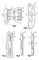
- FIG. 6 is a sectional perspective view a disk of the motor
- FIG. 7 is a sectional side view of a mold for making the disk of the motor
- FIG. 9 is a sectional side view of the disk after receiving a mounting hole
- FIG. 10 is a sectional side view of a rotor comprising a second embodiment
- FIG. 11 is a sectional side view of the rotor comprising a third embodiment
- FIG. 12 is a sectional side view of a the rotor comprising a variation of the third embodiment
- FIG. 13 is a side view of the core and of coils shown in FIG. 1 ;
- FIG. 14 is an expanded partial view of parts shown in FIG. 13 ;
- FIG. 15 is a view taken on line 15 — 15 of FIG. 14 ;
- FIG. 16 is a view taken on line 16 — 16 of FIG. 14 ;
- FIG. 18 is a sectional side view of the rotor comprising a fourth embodiment
- FIG. 19 is a sectional side view of the rotor comprising a variation of the fourth embodiment.
- FIG. 20 is a sectional side view of the rotor comprising another variation of the fourth embodiment
- FIG. 21 is a view taken on line 21 — 21 of FIG. 20 ;
- FIG. 22 is a sectional side view of the motor comprising a fifth embodiment
- FIG. 23 is a nearsighted sectional side view of the motor comprising a sixth embodiment
- FIG. 24 is a nearsighted sectional side view of the motor comprising a variation of the sixth embodiment
- FIG. 25 is a perspective view of the motor comprising a seventh embodiment
- FIG. 26 is a perspective view of the motor comprising an eighth embodiment.
- FIG. 27 is a perspective view of the motor comprising a variation of the eighth embodiment.
- FIG. 1 An embodiment of the present invention is shown in FIG. 1 .
- the embodiment is a brushless motor 10 .
- a stator 12 of the motor 10 has coils 14 toroidally wound on a ring-shaped core 16 .
- a rotor 18 of the motor 10 has two magnet assemblies 20 that are disposed on either side of the core 16 and mounted on a rotatable shaft 22 .
- a stationary plastic housing 24 of the motor 10 encases the stator 12 and the rotor 18 .
- the coils 14 are powered by a motor controller (not shown) that activates the coils 14 in a sequence that rotates the rotor 18 relative to the stator 12 .
- the shaft 22 is of steel and is centered on an axis of rotation 26 .
- the shaft 22 is received by two bearings 27 that are mounted on the housing 24 .
- the bearings 27 are low-friction sleeves configured to enable the shaft 22 to rotate about the axis 26 .
- the core 16 is centered on the axis 26 .
- the core 16 is bounded by two flat side surfaces 30 , a cylindrical radially-inner surface 32 and a cylindrical radially-outer surface 34 .
- the core 16 has an inner diameter ID c , an outer diameter OD c and a thickness T c .
- the cross-sectional profile of the core 16 is rectangular, and can be square. The profile is centered on an annular axis 36 , which runs lengthwise through the core 16 .
- the core 16 has a central section 38 that is magnetically permeable and resistant to eddy currents that would circulate along the skin of the side surfaces 30 of the core 16 . To achieve this, the central section 38 is formed of a tightly spirally wound steel tape.
- the core 16 also has two annular overlapping sections 42 , 43 extending respectively along the radially-inner surface 30 and the radially-outer surface 34 .
- the overlapping sections 42 , 43 are magnetically permeable.
- the overlapping sections 42 , 43 are resistant to eddy currents that would circulate along the skin of any of the surfaces 30 , 32 , 34 of the core 16 .
- the overlapping sections 42 , 43 are formed of turns of a magnetically permeable wire 44 .
- the overlapping sections 42 , 43 can be formed of compressed iron-based powder. The ring is coated on all sides with enamel (not shown).
- each magnet assembly 20 includes a ring-shaped magnet 46 .
- each magnet 46 is a permanently magnetized multi-pole magnet.
- Each magnet 46 has two north-south poles 48 interspersed between two south-north poles 50 .
- the poles 48 , 50 are symmetrically disposed about the axis 26 and aligned axially. Boundaries 52 between neighboring poles 48 , 50 extend radially and are spaced 90° apart.
- Each pole 48 , 50 has a generally trapezoid shape with two straight side edges 52 , an arcuate radially-inner edge 56 and an arcuate radially-outer edge 58 .
- each magnet 46 is formed of C8 ferrite that is molded as a single-piece structure.
- FIG. 4 shows the orientation of the magnets 46 relative to the core 16 when the motor 10 ( FIG. 1 ) is assembled.
- Each magnet 46 has flat axially-inner and axially-outer surfaces 60 , 62 .
- the axially-inner surfaces 60 of the magnets 46 are adjacent to and face the side surfaces 30 of the core 16 .
- the inner diameter ID m of the magnets is smaller than the inner diameter ID c of the core.
- each magnet 46 has an inner overhang 64 , which is the section of the magnet 46 that extends radially inward from the core ID c .
- the radial length L i of the inner overhang is approximately equal to the spacing S m between the axially-inner surfaces 60 of the magnets 46 .
- each magnet 46 has an outer overhang 65 , which is the section of the magnet 46 that extends radially outward from the core outer diameter OD c .
- the radial length L o of the outer overhang 65 is also approximately equal to the spacing S m between the axially-inner surfaces 60 of the magnets 46 .
- the flux gap G f is configured as small as possible to maximize flux.
- the magnets 46 are parallel to each other and aligned north-facing-north and south-facing-south.
- a profile of flux lines 66 is shown.
- the inner and outer overhangs 64 , 65 provide flux through the radially-inner and radially-outer surfaces 32 , 34 of the core 16 .
- the portions of the magnets 46 that face the core 16 are attracted axially inward toward the core 16 .
- the overhangs 64 , 65 repel each other axially outward. These attractive and repulsive forces substantially cancel each other out.
- the overhangs 64 , 65 thus reduce stresses in the magnet assemblies 20 caused by the attractive force.
- the magnet assemblies 20 ( FIG. 1 ) further have identical ring-shaped backplates 68 formed of magnetically permeable material, such as steel.
- the backplates 68 have the same inner diameter ID m and outer diameter OD m as the magnets 46 .
- the backplates 68 are centered on the axis 26 and affixed to the axially-outer surfaces 62 of the magnets 46 to form two magnet/backplate assemblies 70 .
- Each magnet assembly 20 ( FIG. 1 ) further includes a disk 72 , shown in FIG. 6 .
- Each disk 72 has a central bore 74 configured to tightly receive the shaft 22 ( FIG. 1 ) in an interference fit.
- Each disk 72 also has an annular pocket 76 to securely retain the magnet/backplate assembly 70 (FIG. 5 ).
- the disks 72 are formed of a non-magnetically permeable material that contracts as it hardens from a fluid state.
- the material can be zinc or a fiber-reinforced thermoset plastic.
- the process for producing the magnet assembly 20 comprises the following steps.
- the magnet 46 is glued to the backplate 68 to form the magnet/backplate assembly 70 shown in FIG. 5 .
- the magnet/backplate assembly 70 is placed within a mold 78 or die cast cavity, as shown in FIG. 7 .
- the plastic that will form the disk 72 flows into crevices of the magnet/backplate assembly 70 and adheres to the magnet/backplate assembly 70 .
- the plastic contracts about the magnet/backplate assembly 70 to securely hold the magnet/backplate assembly 70 within the disk pocket 76 .
- This yields a rotor blank 80 shown in FIG. 8 comprising the magnet 46 , the backplate 68 and the disk 72 .
- the rotor blank 80 is molded without a mounting hole.
- the rotor blank 80 is mounted on a balance tester (not shown).
- the balance tester indicates the center of gravity of the rotor blank 80 .
- a mounting hole 82 is then drilled into the rotor blank 80 at the center of gravity indicated by the balance tester, to yield the magnet assembly 20 shown in FIG. 9 .
- the balance tester is an apparatus that indicates both an initial drilling location and a drilling angle for the rotor blank 80 .
- the mounting hole 82 is drilled at the initial drilling location and at the drilling angle to yield the magnet assembly 20 shown in FIG. 9 .
- the rotor 18 further comprises a radially-inner magnet 84 centered on the axis 26 and underlying the radially-inner surface 32 of the core 16 .
- the core 16 is thus surrounded on three sides by the magnets 46 , 84 , which can be formed together as a one-piece structure.
- the radially-inner magnet 84 extends axially between the two ring magnets 46 and rotates in unison with the ring magnets 46 .
- the radially-inner magnet 84 has the same sequence of magnetic poles as the ring magnets 46 , with north of the radially-inner magnet 84 adjacent north of the ring magnets 46 and south of the radially-inner magnet 84 adjacent south of the ring magnets 46 .
- the radially-inner magnet 84 has an annular backplate 86 adhering to the radially inner surface 88 of the radially-inner magnet 84 .
- the backplate 86 can be an iron-based ring surrounding the shaft 22 , as shown in FIG. 10 , or can be a portion of the shaft 26 itself.
- the rotor 18 comprises a radially-outer magnet 89 centered on the axis 26 and overlying the radially-outer surface 34 of the core 16 .
- the core 16 is thus surrounded on three sides by the magnets 46 , 89 , which can be formed together as a one-piece structure.
- the radially-outer magnet 89 extends axially between the two ring magnets 46 and rotates in unison with the two magnets 46 .
- the radially-outer magnet 89 has the same sequence of magnetic poles as the ring magnets 46 , with north of the radially-outer magnet 89 adjacent north of the ring magnets 46 and south of the radially-outer magnet 89 adjacent south of the ring magnets 46 .
- the radially-outer magnet 89 has an annular backplate 90 adhering to a radially outer surface 92 of the annular magnet.
- the backplate 90 can be a steel ring.
- the ring magnets 46 and the radially-outer magnet 89 are attached to the shaft 22 through a nonmagnetic disk 93 .
- the core 16 is held in place by a nonmagnetic bracket 94 that extends between the shaft 22 and the core 16 .
- the core 16 can be held in place by a different nonmagnetic bracket 95 that extends radially-outward from the core 16 through an annular opening 96 in the radially-outer magnet 89 .
- the coils 14 are shown in FIG. 13 .
- the coils 14 are formed of insulated electrically-conductive wire, typically copper, toroidally-wound around the core 16 .
- Coils 14 that are connected so as to be electrically activated and deactivated in unison are considered to share a single “phase”.
- This embodiment has three phases, designated A, B and C.
- the coils 14 are sequentially positioned along the length of the core 16 in a sequence A, B, C, A′, B′, C′, A, B, C, A′, B′, C′, etc.
- the prime after a letter indicates reverse winding.
- the four A coils 14 including primed and unprimed, are in series with each other.
- the four B coils 14 are in series
- the four C coils 14 are in series.
- Each coil 14 is generally centered on a radially-projecting coil centerline 100 .
- the core 16 is shown overlying one of the magnets 46 to illustrate how the geometry of the coils 14 is related to the geometry of the magnet poles 48 , 50 .
- the angular spacing (90° in this embodiment) between coil centerlines 100 of a single phase equals the angular spacing (90°) between pole centerlines 102 .
- the angular spacing (90° in this embodiment) between coil boundaries 104 of the same single phase equals the angular spacing (90°) between pole boundaries 52 .
- each coil 14 comprises one layer of turns 110 .
- the turns are closely packed and substantially parallel to the coil centerline 100 .
- Each turn of the coil 14 comprises two radially-extending legs 112 , a radially-inner end turn 114 , and a radially-outer end turn 116 .
- the coil 14 has a bundle thickness T b .
- the wire has a rectangular, preferably square, profile. This yields lower resistive loss than a similar coil using round wire.
- Brackets 120 Spaces 118 between adjacent coils 14 are filled by brackets 120 , such as one shown in FIG. 17 .
- Each bracket 120 comprises two identical generally triangular flanges 122 having rounded edges 124 that are connected by a bowed rectangular flange 126 .
- the flange thickness T f of the triangler flanges 122 and the rectangular flange 126 approximately equals the bundle thickness T b ( FIG. 15 ) of the coils 14 .
- the bracket 120 also has a mounting flange 128 extending perpendicularly from the rectangular flange 122 .
- a chain of the brackets 120 can be molded as one piece, with neighboring brackets 120 held together by a thin plastic web.
- the brackets 120 are shown mounted on the core 16 .
- the triangular flanges 122 of each bracket abuts the side surfaces 30 of the core 16
- the rectangular flange 124 abuts the radially-outer surface 34 of the core 16 .
- the mounting flange 128 extends to any suitable section of the housing 24 ( FIG. 1 ) to mount the bracket 120 , and thus the core 16 , to the housing 24 .
- the brackets 120 provide a smooth flat side surface defined jointly by the radially-extending legs 112 of the coils 14 and the side flanges 122 of the brackets 120 .
- the brackets 120 also thus provide a smooth cylindrical surface defined jointly by the radially-outer turns 116 of the coils 14 and the rectangular flanges 126 of the brackets 120 .
- the brackets 120 serve three functions. They reduce wind turbulence during rotation of the rotor 18 ; they impart and maintain proper positioning of the coil turns 110 ; and they connect the core 16 to the housing 24 .
- the brackets 120 are formed of a non-magnetically permeable material, so as not to affect the magnet flux.
- the triangular flanges 122 and/or the rectangular flange 126 are formed of a magnetically permeability, low eddy current loss material, such as compressed powdered iron, so as to effectively narrow the flux gap G f (FIG. 4 ).
- the stator 12 and rotor 18 are installed in the housing 24 .
- the coils 14 are connected to a brushless motor controller (not shown) to be activated in a manner known in the art.
- the controller can apply forward current, reverse current, or no current.
- the controller applies current to the phases in a sequence that continuously imparts torque to turn the magnet assemblies 20 in a desired direction.
- the controller can decode the rotor position from signals from Hall effect switches or can infer the rotor position based on current drawn by each phase.
- the core 16 has a rectangular profile with planar side surfaces 30 , as shown in FIG. 2 .
- the side surfaces 30 of the core 16 are bowed outward.
- One example of bowed sides is shown in FIG. 18 .
- the profile is generally lenticular and is thickest at a location about 50-75% of the way from the radially-inner surface 32 to the radially-outer surface 34 . This profile renders the core 16 thickest were the flux is strongest and thinnest where the flux is weakest. This profile also reduces the length of the end turns 114 , 116 (FIG. 15 ), which are the legs of the coil 14 that contribute the least torque per resistive loss.
- this fourth embodiment includes a radially-inner magnet 84 .
- the radially-inner magnet 84 is one-piece with the ring magnets 46 .
- this fourth embodiment includes a radially-outer magnet 89 , comprising two sections 132 on either side of an opening 134 .
- the magnets 46 , 84 , 89 can be magnetized such that each flux line 66 is generally perpendicular to the section of the core surface 30 and/or the magnet surface 60 that the flux line 66 intersects.
- FIG. 19 Another example of bowed sides is shown in FIG. 19 .
- the profile of the core 16 is oval.
- the profiles of both the axially-inner and axially-outer surfaces of the magnet match the profile of the core 16 .
- the core 10 is surrounded on four sides by magnets 46 , 84 , 89 .
- the core 16 has an annular cavity 136 that extends circumferentially through the core 16 .
- the cavity 136 serves as an internal cooling channel.
- An inlet 140 and an outlet 142 extend radially outward from opposite ends of the cooling channel 136 .
- Tubes 144 attached to the inlet 140 and the outlet 142 enable cooling fluid to be pumped through the cooling channel 136 .
- the first embodiment ( FIG. 4 ) comprises one core 16 disposed between two backplated magnets 46 .
- This is considered a single-stage motor.
- a fifth embodiment, shown in FIG. 22 includes a second stage 150 , comprising a second core 152 and a non-backplated rotating magnet 154 , and also a third stage 160 , comprising a third core 162 and another non-backplated magnet 164 .
- the second and third stages 150 , 160 are interposed between the first core 16 and one of the backplated magnets 46 .
- the cores 16 , 152 , 162 are interspersed between the magnets 46 , 154 , 164 .
- the second and third cores 152 , 162 are mounted to the housing 24 ( FIG.
- the motor 10 thus is stackable. This stackability enables a manufacturer to build a motor of any desired torque with an inventory of a single-size of magnets and cores.
- the first embodiment, shown in FIG. 4 includes two magnets 46 spaced axially from the core 16 .
- the two ring-shaped magnets 46 are spaced radially from the core 16 —specifically, radially inward and radially outward from the core 16 .
- the motor 10 can have only one ring-shaped magnet 46 .
- the magnets 46 axially-overhang the core 16 , similar to the magnets 46 radially overhanging the core 16 in embodiment of FIG. 4 .
- the core 16 and the magnets 46 , 84 , 89 are each arcuate and form an endless ring.
- the core 16 can be arcuate and have ends 170 , thus forming an incomplete ring.
- the magnets 46 can be arcuate and have ends 172 . This is most suitable in an embodiment in which the magnets 46 , 84 , 89 have a limited range of rotational motion about the axis 22 .
- the profiles of the magnets 46 overhang the profile of the core 16 .
- the magnets 46 do not rotate but rather move linearly relative to the core 16 .
- the coils (not shown) are wound about the core 16 and sequentially disposed along the length of the core 16 .
- the magnets 46 overhang the core 16 .
- FIG. 27 the core 16 is surrounded on three sides by a magnet 174 that also overhangs the core 16 .
- the magnets 46 , 174 have a backplate 68 .
- An “electrical machine” herein is any device that has both stationary and moving parts and that can convert electrical power into mechanical motion, or vice versa.
- An electrical machine can be, for example, a generator, a motor, an actuator, or a motion sensor.
- the present invention can apply to any of such machines.
- the core 16 FIG. 1
- the magnet assemblies 20 are part of the rotor 18 , the opposite is also within the scope of the invention.
- each magnet described as though they are separate structures can equivalently be formed together as a one-piece structure.
- each magnet described as though it were a one-piece structure can equivalently be formed of separate parts combined together. Consequently, for example, in the claims, “surrounded on three sides by a magnet” is equivalent to “surrounded on three sides by magnets.”
- the “lengthwise direction” or “along the length” herein can refer to either a linear path, an open arcuate path, or a closed circumferential path such as the annular axis 36 (FIG. 2 ).
- the term “elongated” herein can characterize the shape of a closed ring, as well as a straight structure, by defining the structure as having a profile that extends uniformly along a circumference.
Landscapes
- Engineering & Computer Science (AREA)
- Power Engineering (AREA)
- Iron Core Of Rotating Electric Machines (AREA)
- Permanent Field Magnets Of Synchronous Machinery (AREA)
Abstract
An electrical machine includes first and second magnetically permeable parallel cores. Each core is elongated to thereby define a lengthwise direction and first and second core profiles transverse to the lengthwise direction. First coils are wound about the first core profile and sequentially disposed along the length of the first core. Second coils are wound about the second core profile and sequentially disposed along the length of the second core. A multi-pole elongated permanent magnet is parallel with the cores and located between them. The magnet is movable, relative to the cores, in the lengthwise direction.
Description
This is a division of U.S. application Ser. No. 10/614,371, filed Jul. 7, 2003 now U.S. Pat. No. 6,803,691, hereby incorporated herein by reference, which is a continuation of U.S. application Ser. No. 09/923,484, filed Aug. 6, 2001, now U.S. Pat. No. 6,664,689.
This application relates to permanent magnet motors.
A motor comprises a multi-pole ring-shaped magnet that rotates relative to a stator. The stator comprises multiple coils toroidally-wound about a ring-shaped core and sequentially disposed along the circumference of the core.
An embodiment of the present invention is shown in FIG. 1. The embodiment is a brushless motor 10. A stator 12 of the motor 10 has coils 14 toroidally wound on a ring-shaped core 16. A rotor 18 of the motor 10 has two magnet assemblies 20 that are disposed on either side of the core 16 and mounted on a rotatable shaft 22. A stationary plastic housing 24 of the motor 10 encases the stator 12 and the rotor 18. The coils 14 are powered by a motor controller (not shown) that activates the coils 14 in a sequence that rotates the rotor 18 relative to the stator 12.
The shaft 22 is of steel and is centered on an axis of rotation 26. The shaft 22 is received by two bearings 27 that are mounted on the housing 24. The bearings 27 are low-friction sleeves configured to enable the shaft 22 to rotate about the axis 26.
As shown in FIG. 2 , the core 16 is centered on the axis 26. The core 16 is bounded by two flat side surfaces 30, a cylindrical radially-inner surface 32 and a cylindrical radially-outer surface 34. The core 16 has an inner diameter IDc, an outer diameter ODc and a thickness Tc. The cross-sectional profile of the core 16 is rectangular, and can be square. The profile is centered on an annular axis 36, which runs lengthwise through the core 16. The core 16 has a central section 38 that is magnetically permeable and resistant to eddy currents that would circulate along the skin of the side surfaces 30 of the core 16. To achieve this, the central section 38 is formed of a tightly spirally wound steel tape.
The core 16 also has two annular overlapping sections 42, 43 extending respectively along the radially-inner surface 30 and the radially-outer surface 34. Like the central section 38, the overlapping sections 42, 43 are magnetically permeable. The overlapping sections 42, 43 are resistant to eddy currents that would circulate along the skin of any of the surfaces 30, 32, 34 of the core 16. To achieve this, the overlapping sections 42, 43 are formed of turns of a magnetically permeable wire 44. Alternatively, the overlapping sections 42, 43 can be formed of compressed iron-based powder. The ring is coated on all sides with enamel (not shown).
As shown in FIG. 1 , the two magnet assemblies 20 are alike, centered on the axis 26, and facing each other from opposite sides of the core 16. Each magnet assembly 20 includes a ring-shaped magnet 46. As shown in FIG. 3 , each magnet 46 is a permanently magnetized multi-pole magnet. Each magnet 46 has two north-south poles 48 interspersed between two south-north poles 50. The poles 48, 50 are symmetrically disposed about the axis 26 and aligned axially. Boundaries 52 between neighboring poles 48, 50 extend radially and are spaced 90° apart. Each pole 48, 50 has a generally trapezoid shape with two straight side edges 52, an arcuate radially-inner edge 56 and an arcuate radially-outer edge 58. In this embodiment, each magnet 46 is formed of C8 ferrite that is molded as a single-piece structure.
As shown in FIG. 5 , the magnets 46 are parallel to each other and aligned north-facing-north and south-facing-south. A profile of flux lines 66 is shown. The inner and outer overhangs 64, 65 provide flux through the radially-inner and radially- outer surfaces 32, 34 of the core 16. The portions of the magnets 46 that face the core 16 are attracted axially inward toward the core 16. The overhangs 64, 65 repel each other axially outward. These attractive and repulsive forces substantially cancel each other out. The overhangs 64, 65 thus reduce stresses in the magnet assemblies 20 caused by the attractive force.
The magnet assemblies 20 (FIG. 1 ) further have identical ring-shaped backplates 68 formed of magnetically permeable material, such as steel. The backplates 68 have the same inner diameter IDm and outer diameter ODm as the magnets 46. The backplates 68 are centered on the axis 26 and affixed to the axially-outer surfaces 62 of the magnets 46 to form two magnet/backplate assemblies 70.
Each magnet assembly 20 (FIG. 1 ) further includes a disk 72, shown in FIG. 6. Each disk 72 has a central bore 74 configured to tightly receive the shaft 22 (FIG. 1 ) in an interference fit. Each disk 72 also has an annular pocket 76 to securely retain the magnet/backplate assembly 70 (FIG. 5). The disks 72 are formed of a non-magnetically permeable material that contracts as it hardens from a fluid state. The material can be zinc or a fiber-reinforced thermoset plastic.
The process for producing the magnet assembly 20 (FIG. 1 ) comprises the following steps. The magnet 46 is glued to the backplate 68 to form the magnet/backplate assembly 70 shown in FIG. 5. The magnet/backplate assembly 70 is placed within a mold 78 or die cast cavity, as shown in FIG. 7. Within the mold 78, the plastic that will form the disk 72 flows into crevices of the magnet/backplate assembly 70 and adheres to the magnet/backplate assembly 70. As the plastic hardens, the plastic contracts about the magnet/backplate assembly 70 to securely hold the magnet/backplate assembly 70 within the disk pocket 76. This yields a rotor blank 80 shown in FIG. 8 , comprising the magnet 46, the backplate 68 and the disk 72. The rotor blank 80 is molded without a mounting hole. Next, the rotor blank 80 is mounted on a balance tester (not shown). The balance tester indicates the center of gravity of the rotor blank 80. A mounting hole 82 is then drilled into the rotor blank 80 at the center of gravity indicated by the balance tester, to yield the magnet assembly 20 shown in FIG. 9. Alternatively, the balance tester is an apparatus that indicates both an initial drilling location and a drilling angle for the rotor blank 80. Then the mounting hole 82 is drilled at the initial drilling location and at the drilling angle to yield the magnet assembly 20 shown in FIG. 9.
In a second embodiment of the invention, shown in FIG. 10 , the rotor 18 further comprises a radially-inner magnet 84 centered on the axis 26 and underlying the radially-inner surface 32 of the core 16. The core 16 is thus surrounded on three sides by the magnets 46, 84, which can be formed together as a one-piece structure. The radially-inner magnet 84 extends axially between the two ring magnets 46 and rotates in unison with the ring magnets 46. The radially-inner magnet 84 has the same sequence of magnetic poles as the ring magnets 46, with north of the radially-inner magnet 84 adjacent north of the ring magnets 46 and south of the radially-inner magnet 84 adjacent south of the ring magnets 46. The radially-inner magnet 84 has an annular backplate 86 adhering to the radially inner surface 88 of the radially-inner magnet 84. The backplate 86 can be an iron-based ring surrounding the shaft 22, as shown in FIG. 10 , or can be a portion of the shaft 26 itself.
In a third embodiment, shown in FIG. 11 , the rotor 18 comprises a radially-outer magnet 89 centered on the axis 26 and overlying the radially-outer surface 34 of the core 16. The core 16 is thus surrounded on three sides by the magnets 46, 89, which can be formed together as a one-piece structure. The radially-outer magnet 89 extends axially between the two ring magnets 46 and rotates in unison with the two magnets 46. The radially-outer magnet 89 has the same sequence of magnetic poles as the ring magnets 46, with north of the radially-outer magnet 89 adjacent north of the ring magnets 46 and south of the radially-outer magnet 89 adjacent south of the ring magnets 46. The radially-outer magnet 89 has an annular backplate 90 adhering to a radially outer surface 92 of the annular magnet. The backplate 90 can be a steel ring. The ring magnets 46 and the radially-outer magnet 89 are attached to the shaft 22 through a nonmagnetic disk 93. The core 16 is held in place by a nonmagnetic bracket 94 that extends between the shaft 22 and the core 16. Alternatively, as shown in FIG. 12 , the core 16 can be held in place by a different nonmagnetic bracket 95 that extends radially-outward from the core 16 through an annular opening 96 in the radially-outer magnet 89.
The coils 14 are shown in FIG. 13. The coils 14 are formed of insulated electrically-conductive wire, typically copper, toroidally-wound around the core 16. Coils 14 that are connected so as to be electrically activated and deactivated in unison are considered to share a single “phase”. This embodiment has three phases, designated A, B and C. The coils 14 are sequentially positioned along the length of the core 16 in a sequence A, B, C, A′, B′, C′, A, B, C, A′, B′, C′, etc. The prime after a letter indicates reverse winding. In this embodiment, the four A coils 14, including primed and unprimed, are in series with each other. Similarly, the four B coils 14 are in series, and the four C coils 14 are in series. Each coil 14 is generally centered on a radially-projecting coil centerline 100.
In FIG. 13 , the core 16 is shown overlying one of the magnets 46 to illustrate how the geometry of the coils 14 is related to the geometry of the magnet poles 48, 50. The angular spacing (90° in this embodiment) between coil centerlines 100 of a single phase equals the angular spacing (90°) between pole centerlines 102. Similarly, the angular spacing (90° in this embodiment) between coil boundaries 104 of the same single phase equals the angular spacing (90°) between pole boundaries 52.
The coils 14 in this embodiment are alike. The structure of the coils 14 is illustrated in FIGS. 14-16 , with reference to one of the coils 14. In this embodiment, each coil 14 comprises one layer of turns 110. The turns are closely packed and substantially parallel to the coil centerline 100. Each turn of the coil 14 comprises two radially-extending legs 112, a radially-inner end turn 114, and a radially-outer end turn 116. The coil 14 has a bundle thickness Tb. The wire has a rectangular, preferably square, profile. This yields lower resistive loss than a similar coil using round wire.
In FIGS. 14 and 16 , the brackets 120 are shown mounted on the core 16. The triangular flanges 122 of each bracket abuts the side surfaces 30 of the core 16, and the rectangular flange 124 abuts the radially-outer surface 34 of the core 16. The mounting flange 128 extends to any suitable section of the housing 24 (FIG. 1 ) to mount the bracket 120, and thus the core 16, to the housing 24. By filling in the coil-free spaces 118, the brackets 120 provide a smooth flat side surface defined jointly by the radially-extending legs 112 of the coils 14 and the side flanges 122 of the brackets 120. The brackets 120 also thus provide a smooth cylindrical surface defined jointly by the radially-outer turns 116 of the coils 14 and the rectangular flanges 126 of the brackets 120. The brackets 120 serve three functions. They reduce wind turbulence during rotation of the rotor 18; they impart and maintain proper positioning of the coil turns 110; and they connect the core 16 to the housing 24.
The brackets 120 are formed of a non-magnetically permeable material, so as not to affect the magnet flux. In a variation of this embodiment, the triangular flanges 122 and/or the rectangular flange 126 are formed of a magnetically permeability, low eddy current loss material, such as compressed powdered iron, so as to effectively narrow the flux gap Gf (FIG. 4).
Referring to FIG. 1 , the stator 12 and rotor 18 are installed in the housing 24. The coils 14 are connected to a brushless motor controller (not shown) to be activated in a manner known in the art. For each phase, the controller can apply forward current, reverse current, or no current. In operation, the controller applies current to the phases in a sequence that continuously imparts torque to turn the magnet assemblies 20 in a desired direction. The controller can decode the rotor position from signals from Hall effect switches or can infer the rotor position based on current drawn by each phase.
In the first embodiment, the core 16 has a rectangular profile with planar side surfaces 30, as shown in FIG. 2. In contrast, in a fourth embodiment, the side surfaces 30 of the core 16 are bowed outward. One example of bowed sides is shown in FIG. 18. The profile is generally lenticular and is thickest at a location about 50-75% of the way from the radially-inner surface 32 to the radially-outer surface 34. This profile renders the core 16 thickest were the flux is strongest and thinnest where the flux is weakest. This profile also reduces the length of the end turns 114, 116 (FIG. 15), which are the legs of the coil 14 that contribute the least torque per resistive loss.
The surfaces 60 of the magnets 46 that face the outwardly-bowed surfaces 30 of the core 16 are bowed inward to yield a gap thickness Tg that is uniform along a significant portion of the periphery of the core profile. Like the second embodiment (FIG. 10), this fourth embodiment includes a radially-inner magnet 84. However, unlike the second embodiment, the radially-inner magnet 84 is one-piece with the ring magnets 46. Like the third embodiment (FIG. 12), this fourth embodiment includes a radially-outer magnet 89, comprising two sections 132 on either side of an opening 134. As illustrated in this embodiment, the magnets 46, 84, 89 can be magnetized such that each flux line 66 is generally perpendicular to the section of the core surface 30 and/or the magnet surface 60 that the flux line 66 intersects.
Another example of bowed sides is shown in FIG. 19. The profile of the core 16 is oval. In this variation, the profiles of both the axially-inner and axially-outer surfaces of the magnet match the profile of the core 16. In the examples of FIGS. 18-19 , the core 10 is surrounded on four sides by magnets 46, 84, 89.
Another feature is shown in FIGS. 20 and 21 . The core 16 has an annular cavity 136 that extends circumferentially through the core 16. The cavity 136 serves as an internal cooling channel. An inlet 140 and an outlet 142 extend radially outward from opposite ends of the cooling channel 136. Tubes 144 attached to the inlet 140 and the outlet 142 enable cooling fluid to be pumped through the cooling channel 136.
The first embodiment (FIG. 4 ) comprises one core 16 disposed between two backplated magnets 46. This is considered a single-stage motor. A fifth embodiment, shown in FIG. 22 , includes a second stage 150, comprising a second core 152 and a non-backplated rotating magnet 154, and also a third stage 160, comprising a third core 162 and another non-backplated magnet 164. The second and third stages 150, 160 are interposed between the first core 16 and one of the backplated magnets 46. Thus, the cores 16, 152, 162 are interspersed between the magnets 46, 154, 164. The second and third cores 152, 162 are mounted to the housing 24 (FIG. 1 ) in any suitable manner, and the non-backplated magnets 154, 164 are mounted to the shaft 22 in any suitable manner. The added stages 150, 160 provide additional motor torque. Any number of such stages is possible. The motor 10 thus is stackable. This stackability enables a manufacturer to build a motor of any desired torque with an inventory of a single-size of magnets and cores.
The first embodiment, shown in FIG. 4 includes two magnets 46 spaced axially from the core 16. In contrast, in a sixth embodiment, shown in FIG. 23 , the two ring-shaped magnets 46 are spaced radially from the core 16—specifically, radially inward and radially outward from the core 16. Also, alternatively, as shown in FIG. 24 , the motor 10 can have only one ring-shaped magnet 46. In the embodiments of FIGS. 23 and 24 , the magnets 46 axially-overhang the core 16, similar to the magnets 46 radially overhanging the core 16 in embodiment of FIG. 4.
In the previous embodiments (FIGS. 1-24), the core 16 and the magnets 46, 84, 89 are each arcuate and form an endless ring. However, in a seventh embodiment shown in FIG. 25 , the core 16 can be arcuate and have ends 170, thus forming an incomplete ring. Similarly, the magnets 46 can be arcuate and have ends 172. This is most suitable in an embodiment in which the magnets 46, 84, 89 have a limited range of rotational motion about the axis 22. In this embodiment, the profiles of the magnets 46 overhang the profile of the core 16.
In an eighth embodiment shown in FIG. 26 , the magnets 46 do not rotate but rather move linearly relative to the core 16. The coils (not shown) are wound about the core 16 and sequentially disposed along the length of the core 16. In this embodiment, the magnets 46 overhang the core 16. A variation of this embodiment, shown in FIG. 27 , the core 16 is surrounded on three sides by a magnet 174 that also overhangs the core 16. In both embodiments (FIGS. 26 and 27), the magnets 46, 174 have a backplate 68.
An “electrical machine” herein is any device that has both stationary and moving parts and that can convert electrical power into mechanical motion, or vice versa. An electrical machine can be, for example, a generator, a motor, an actuator, or a motion sensor. The present invention can apply to any of such machines. Although, in the embodiments described above, the core 16 (FIG. 1 ) is part of the stator 12 and the magnet assemblies 20 are part of the rotor 18, the opposite is also within the scope of the invention.
In each of the embodiments, several magnets described as though they are separate structures can equivalently be formed together as a one-piece structure. Conversely, in each of the embodiments, each magnet described as though it were a one-piece structure can equivalently be formed of separate parts combined together. Consequently, for example, in the claims, “surrounded on three sides by a magnet” is equivalent to “surrounded on three sides by magnets.”
The “lengthwise direction” or “along the length” herein can refer to either a linear path, an open arcuate path, or a closed circumferential path such as the annular axis 36 (FIG. 2). The term “elongated” herein can characterize the shape of a closed ring, as well as a straight structure, by defining the structure as having a profile that extends uniformly along a circumference.
The embodiments described above are chosen to be included herein only due to their being good examples of or best modes of practicing the invention. The scopes of the claims are therefore not intended to be limited by these embodiments.
Claims (13)
1. An electrical machine comprising:
three or more elongated parallel multi-pole permanent magnets, located side-by-side and aligned such that south poles of adjacent magnets face each other and north poles of adjacent magnets face each other, the magnets including two endmost magnets and one or more non-endmost magnets;
magnetically permeable cores, each core being elongated to thereby define a lengthwise direction and a core profile transverse to the lengthwise direction, the cores being parallel with and interspersed between the magnets, with each core located between a corresponding pair of adjacent magnets, the cores being interconnected so as to be fixed relative to each other, and the magnets being interconnected so as to move in unison, in the lengthwise direction, relative to the cores;
coils wound about the profile of each core and sequentially disposed along the length of the core; and
a ferromagnetic backplate fixedly capping each of the two endmost magnets, with none of the non-endmost magnets being capped by a backplate to enable flux lines to extend through each non-endmost magnet from one adjacent core to another.
2. The machine of claim 1 wherein the lengthwise direction extends about an axis of rotation such that the elongated cores are ring-shaped and centered on the axis and the coils axe toroidally wound about the cores and sequentially disposed about the axis.
3. An electrical machine comprising:
three or more multi-pole ring-shaped permanent magnets, all centered on a rotational axis and located side-by-side along the axis, and aligned such that south poles of adjacent magnets face each other and north poles of adjacent magnets face each other, the magnets including two endmost magnets and one or more non-endmost magnets;
magnetically permeable ring-shaped cores, centered on the axis and interspersed between the magnets, with each core located between a corresponding pair of magnets, the cores being interconnected so as to be fixed relative to each other, and the magnets being interconnected so as to rotate in unison about the axis relative to the cores;
coils toroidally wound about each core and disposed sequentially along the circumference of the core; and
a ferromagnetic backplate fixedly capping each endmost magnet, with none of the non-endmost magnets being capped by a backplate to enable flux lines to extend axially through each non-endmost magnet from one adjacent core to another.
4. The machine of claim 3 wherein each core has axially opposite side surfaces that are bowed axially outward.
5. The machine of claim 3 wherein each magnet has a surface that is bowed axially inwardly.
6. The machine of claim 3 wherein each core includes turns of magnetically permeable wire.
7. The machine of claim 3 wherein at least one of the cores has an outer diameter smaller than the outer diameter of an adjacent magnet, and the core includes an annular radially-outer section formed of turns of magnetically permeable wire.
8. The machine of claim 3 wherein at least one of the cores has an inner diameter larger than the inner diameter of an adjacent magnet, and the core includes an annular radially-inner section formed of turns of magnetically permeable wire.
9. The machine of claim 3 further comprising another ring magnet centered on the axis and radially underlying one of the cores.
10. The machine of claim 3 further comprising another ring magnet centered on the axis and radially overlying one of the cores.
11. The machine of claim 3 further comprising a non-magnetically-permeable flange fixedly overlying a side surface of one of the cores such that flux lines can extend from an adjacent one of the magnets through the flange to the core, the flange being located between two adjacent coils and extending from one of the adjacent coils to the other.
12. The machine of claim 3 further comprising a bracket mounting one of the cores in place and located in-between two adjacent coils, the bracket including first and second side flanges overlying first and second side surfaces of the mounted core and a bridging flange extending from the first side flange to the second side flange.
13. The machine of claim 12 wherein the axially-outer surface of the first flange and a leg of a coil adjacent the first flange together define a flat outer surface to reduce wind turbulence.
Priority Applications (1)
| Application Number | Priority Date | Filing Date | Title |
|---|---|---|---|
| US10/833,101 US6930422B2 (en) | 2001-08-06 | 2004-04-28 | Multi-stage motor |
Applications Claiming Priority (3)
| Application Number | Priority Date | Filing Date | Title |
|---|---|---|---|
| US09/923,484 US6664689B2 (en) | 2001-08-06 | 2001-08-06 | Ring-shaped motor core with toroidally-wound coils |
| US10/614,371 US6803691B2 (en) | 2001-08-06 | 2003-07-07 | Ring-shaped motor core |
| US10/833,101 US6930422B2 (en) | 2001-08-06 | 2004-04-28 | Multi-stage motor |
Related Parent Applications (1)
| Application Number | Title | Priority Date | Filing Date |
|---|---|---|---|
| US10/614,371 Division US6803691B2 (en) | 2001-08-06 | 2003-07-07 | Ring-shaped motor core |
Publications (2)
| Publication Number | Publication Date |
|---|---|
| US20040195932A1 US20040195932A1 (en) | 2004-10-07 |
| US6930422B2 true US6930422B2 (en) | 2005-08-16 |
Family
ID=25448756
Family Applications (5)
| Application Number | Title | Priority Date | Filing Date |
|---|---|---|---|
| US09/923,484 Expired - Fee Related US6664689B2 (en) | 2001-08-06 | 2001-08-06 | Ring-shaped motor core with toroidally-wound coils |
| US10/614,371 Expired - Fee Related US6803691B2 (en) | 2001-08-06 | 2003-07-07 | Ring-shaped motor core |
| US10/833,102 Expired - Fee Related US7049722B2 (en) | 2001-08-06 | 2004-04-28 | Motor core construction |
| US10/833,155 Abandoned US20040194286A1 (en) | 2001-08-06 | 2004-04-28 | Method of making a ring-magnet assembly |
| US10/833,101 Expired - Fee Related US6930422B2 (en) | 2001-08-06 | 2004-04-28 | Multi-stage motor |
Family Applications Before (4)
| Application Number | Title | Priority Date | Filing Date |
|---|---|---|---|
| US09/923,484 Expired - Fee Related US6664689B2 (en) | 2001-08-06 | 2001-08-06 | Ring-shaped motor core with toroidally-wound coils |
| US10/614,371 Expired - Fee Related US6803691B2 (en) | 2001-08-06 | 2003-07-07 | Ring-shaped motor core |
| US10/833,102 Expired - Fee Related US7049722B2 (en) | 2001-08-06 | 2004-04-28 | Motor core construction |
| US10/833,155 Abandoned US20040194286A1 (en) | 2001-08-06 | 2004-04-28 | Method of making a ring-magnet assembly |
Country Status (1)
| Country | Link |
|---|---|
| US (5) | US6664689B2 (en) |
Cited By (19)
| Publication number | Priority date | Publication date | Assignee | Title |
|---|---|---|---|---|
| US20070222326A1 (en) * | 2005-12-08 | 2007-09-27 | A.O. Smith Corporation | Rotor assembly having a reduced back portion and a method of manufacturing same |
| US20080252164A1 (en) * | 2007-04-16 | 2008-10-16 | Shi-Bing Huang | Variable speed motor |
| US20090191422A1 (en) * | 2008-01-30 | 2009-07-30 | United Technologies Corporation | Cathodic ARC deposition coatings for turbine engine components |
| US20100171451A1 (en) * | 2009-01-05 | 2010-07-08 | Eric Stephane Quere | Integrated composite electromechanical machines |
| US20100253085A1 (en) * | 2007-09-14 | 2010-10-07 | Takehisa Minowa | Permanent magnet rotating machine |
| US20110233938A1 (en) * | 2010-03-25 | 2011-09-29 | Henrik Stiesdal | Stator arrangement for an electromechanical transducer, electromechanical transducer and wind turbine |
| CN103138516A (en) * | 2011-11-22 | 2013-06-05 | 陈启川 | High-effect silicon-free steel sheet generator |
| US8536747B1 (en) * | 2011-01-03 | 2013-09-17 | Thomas E. Baggett | Direct current multi-stage motor |
| US20130300252A1 (en) * | 2012-05-04 | 2013-11-14 | Electric Force Motors, LLC | Electrostatic machine |
| US9729016B1 (en) | 2012-03-20 | 2017-08-08 | Linear Labs, Inc. | Multi-tunnel electric motor/generator |
| US9825496B2 (en) | 2012-03-20 | 2017-11-21 | Linear Labs, Inc. | DC electric motor/generator with enhanced permanent magnet flux densities |
| US10263480B2 (en) | 2012-03-20 | 2019-04-16 | Linear Labs, LLC | Brushless electric motor/generator |
| US10284029B2 (en) | 2012-03-20 | 2019-05-07 | Linear Labs, LLC | Brushed electric motor/generator |
| US10447103B2 (en) | 2015-06-28 | 2019-10-15 | Linear Labs, LLC | Multi-tunnel electric motor/generator |
| US10476362B2 (en) | 2015-06-28 | 2019-11-12 | Linear Labs, LLC | Multi-tunnel electric motor/generator segment |
| US10804789B2 (en) * | 2016-08-16 | 2020-10-13 | Yuzen Sustainable Energy Co., Ltd. | Coaxial electromagnetic apparatus |
| US11159076B2 (en) | 2015-10-20 | 2021-10-26 | Linear Labs, Inc. | Circumferential flux electric machine with field weakening mechanisms and methods of use |
| US11277062B2 (en) | 2019-08-19 | 2022-03-15 | Linear Labs, Inc. | System and method for an electric motor/generator with a multi-layer stator/rotor assembly |
| US11309778B2 (en) | 2016-09-05 | 2022-04-19 | Linear Labs, Inc. | Multi-tunnel electric motor/generator |
Families Citing this family (83)
| Publication number | Priority date | Publication date | Assignee | Title |
|---|---|---|---|---|
| US7084548B1 (en) * | 2003-07-11 | 2006-08-01 | Gabrys Christopher W | Low cost high speed electrical machine |
| US7315103B2 (en) * | 2004-03-03 | 2008-01-01 | General Electric Company | Superconducting rotating machines with stationary field coils |
| US7049724B2 (en) * | 2004-03-03 | 2006-05-23 | General Electric Company | Superconducting rotating machines with stationary field coils and axial airgap flux |
| US20070252033A1 (en) * | 2004-08-20 | 2007-11-01 | Dumitru Bojiuc | Discoidal flying craft |
| US20060038456A1 (en) * | 2004-08-20 | 2006-02-23 | Dumitru Bojiuc | Monopole field electric motor generator |
| US7834503B2 (en) * | 2004-08-20 | 2010-11-16 | Clearwater Holdings, Ltd. | Immersed windings, monopole field, electromagnetic rotating machine |
| US7791242B2 (en) * | 2004-08-20 | 2010-09-07 | Clearwater Holdings, Ltd. | DC induction electric motor-generator |
| US7348703B2 (en) * | 2004-08-20 | 2008-03-25 | Dumitru Bojiuc | Monopole field electric motor-generator with switchable coil configuration |
| US20100127579A1 (en) * | 2004-08-20 | 2010-05-27 | Dumitru Bojiuc | Magnetically levitated transport system |
| US7411325B1 (en) * | 2004-10-20 | 2008-08-12 | Revolution Electric Motor Company, Inc. | High efficiency combination motor and drive |
| JP4613599B2 (en) * | 2004-12-14 | 2011-01-19 | 日産自動車株式会社 | Rotor structure of axial gap type rotating electrical machine |
| US8074922B2 (en) * | 2005-08-22 | 2011-12-13 | Dumitru Bojiuc | Discoidal flying craft |
| US8074579B1 (en) | 2005-08-22 | 2011-12-13 | Dumitru Bojiuc | Magnetically levitated transport system |
| GB0526023D0 (en) * | 2005-12-21 | 2006-02-01 | Em Digital Ltd | Electromagnetic actuator |
| US7602157B2 (en) | 2005-12-28 | 2009-10-13 | Flyback Energy, Inc. | Supply architecture for inductive loads |
| US11201500B2 (en) | 2006-01-31 | 2021-12-14 | Mojo Mobility, Inc. | Efficiencies and flexibilities in inductive (wireless) charging |
| CA2549882A1 (en) * | 2006-06-12 | 2007-12-12 | Msi Machineering Solutions Inc. | Axial flux switched reluctance motor |
| US7492073B2 (en) * | 2006-06-30 | 2009-02-17 | General Electric Company | Superconducting rotating machines with stationary field coils |
| US7489060B2 (en) * | 2006-06-30 | 2009-02-10 | General Electric Company | Superconducting rotating machines with stationary field coils |
| US7557482B2 (en) * | 2006-07-31 | 2009-07-07 | Caterpillar Inc. | Axial-flux electric machine |
| US20080024035A1 (en) * | 2006-07-31 | 2008-01-31 | Caterpillar Inc. | Power system |
| US7375449B2 (en) * | 2006-08-17 | 2008-05-20 | Butterfield Paul D | Optimized modular electrical machine using permanent magnets |
| CN101248570A (en) * | 2006-09-14 | 2008-08-20 | 冈本范政 | Generator |
| DE102007002782A1 (en) * | 2007-01-18 | 2008-07-31 | Siemens Ag | Rotary drive with straight primary section segments |
| CN104393724A (en) * | 2007-03-23 | 2015-03-04 | 信越化学工业株式会社 | Permanent magnet generator and wind power generator using the same |
| US7646132B2 (en) * | 2007-05-02 | 2010-01-12 | Empire Magnetics Inc. | Arcuate coil winding and assembly for axial gap electro-dynamo machines (EDM) |
| US20090001831A1 (en) * | 2007-06-26 | 2009-01-01 | Cho Chahee P | Axial Field Electric Motor and Method |
| USRE46449E1 (en) | 2007-07-09 | 2017-06-20 | Clearwater Holdings, Ltd. | Electromagnetic machine with independent removable coils, modular parts and self sustained passive magnetic bearing |
| US7957160B2 (en) * | 2007-09-18 | 2011-06-07 | Flyback Energy, Inc. | Current waveform construction to generate AC power with low harmonic distortion from localized energy sources |
| ITNA20070104A1 (en) * | 2007-10-18 | 2009-04-19 | Oreste Caputi | STATION ALTERNATOR WITH ANGULAR STALLED STATIONS |
| US20090200889A1 (en) * | 2008-02-08 | 2009-08-13 | Empire Magnetics Inc. | Nested Serpentine Winding for an Axial Gap Electric Dynamo Machine |
| US7821168B2 (en) * | 2008-02-10 | 2010-10-26 | Empire Magnetics Inc. | Axial gap dynamo electric machine with magnetic bearing |
| US20090200890A1 (en) * | 2008-02-10 | 2009-08-13 | Empire Magnetics Inc. | Winding For An Axial Gap Electric Dynamo Machine |
| US20090261675A1 (en) * | 2008-04-19 | 2009-10-22 | Hsien-Wei Hsiao | High efficient magnetic energy shifting device |
| US20110050164A1 (en) | 2008-05-07 | 2011-03-03 | Afshin Partovi | System and methods for inductive charging, and improvements and uses thereof |
| US7732973B2 (en) * | 2008-06-25 | 2010-06-08 | Clearwater Holdings, Ltd | Electromagnetic machine with magnetic gap channels |
| GB0813032D0 (en) * | 2008-07-16 | 2008-08-20 | Cummins Generator Technologies | Axial flux machine |
| US20100038987A1 (en) * | 2008-08-14 | 2010-02-18 | Infinite Wind Energy LLC | Motors Having a Hyperbolic Cosine Curve Shape |
| JP2010081784A (en) * | 2008-08-29 | 2010-04-08 | Seiko Epson Corp | Brushless electrical machine and apparatus having the same |
| EP2340602B1 (en) | 2008-09-26 | 2019-01-02 | Clearwater Holdings, Ltd. | Permanent magnet operating machine |
| US8860273B2 (en) * | 2009-12-28 | 2014-10-14 | Flyback Energy, Inc. | External field interaction motor |
| CN102859860A (en) * | 2009-12-28 | 2013-01-02 | 菲莱贝克能源公司 | Controllable universal power supply with reactive power management |
| CA2792877C (en) * | 2010-03-23 | 2014-11-18 | Bell Helicopter Textron Inc. | Swashplate-mounted permanent magnet alternator |
| WO2011156768A2 (en) * | 2010-06-11 | 2011-12-15 | Mojo Mobility, Inc. | System for wireless power transfer that supports interoperability, and multi-pole magnets for use therewith |
| US9325232B1 (en) | 2010-07-22 | 2016-04-26 | Linear Labs, Inc. | Method and apparatus for power generation |
| AU2011316872B2 (en) | 2010-10-22 | 2016-08-04 | Linear Labs, Inc. | An improved magnetic motor |
| JP5460566B2 (en) * | 2010-12-13 | 2014-04-02 | 株式会社日立製作所 | Axial gap type rotating electrical machine |
| US11342777B2 (en) | 2011-01-18 | 2022-05-24 | Mojo Mobility, Inc. | Powering and/or charging with more than one protocol |
| CZ2011293A3 (en) * | 2011-05-17 | 2012-11-28 | Cominfo, A.S. | Direct-current electric motor |
| JP2012244840A (en) * | 2011-05-23 | 2012-12-10 | Asahi Denki Kenkyusho:Kk | Toroidal coil, bobbin coil, air-core coil and winding method thereof |
| US20150137647A1 (en) * | 2012-03-20 | 2015-05-21 | Linear Labs, Inc. | Brushless electric motor/generator |
| US10505412B2 (en) | 2013-01-24 | 2019-12-10 | Clearwater Holdings, Ltd. | Flux machine |
| US10447102B2 (en) * | 2013-03-15 | 2019-10-15 | Regal Beloit Australia Pty. Ltd. | Permanent magnet electrical machines and methods of assembling the same |
| WO2014194134A1 (en) * | 2013-05-29 | 2014-12-04 | ReVair Inc. | Modified halbach array generator |
| JP2015019546A (en) * | 2013-07-12 | 2015-01-29 | 株式会社東芝 | Axial gap type permanent magnet electrical rotating machine, and manufacturing method for the same |
| RU2528983C1 (en) * | 2013-07-23 | 2014-09-20 | Александр Алексеевич Семенов | Brushless rotary electric motor |
| CN203722347U (en) * | 2014-02-27 | 2014-07-16 | 讯凯国际股份有限公司 | Thin axial-air-gap-type motor |
| DE102014103584A1 (en) * | 2014-03-17 | 2015-09-17 | Peter Wetzel | Homopolar machine |
| EP3195452A4 (en) | 2014-07-23 | 2018-01-17 | Clearwater Holdings, Ltd. | Flux machine |
| EP3281285B1 (en) * | 2015-04-08 | 2021-06-30 | Linear Labs, Inc. | An improved multi-tunnel electric motor/generator |
| ES2576104A1 (en) * | 2015-11-13 | 2016-07-05 | José Manuel ALARCÓN PLANES | Electric generator (Machine-translation by Google Translate, not legally binding) |
| US11448524B2 (en) | 2016-04-07 | 2022-09-20 | Phoenix America Inc. | Multipole magnet for use with a pitched magnetic sensor |
| JP6800475B2 (en) * | 2016-08-08 | 2020-12-16 | 学校法人加計学園 | Superconducting rotating machine |
| US10541591B2 (en) | 2017-01-31 | 2020-01-21 | Regal Beloit Australia Pty, Ltd. | Composite stator for axial flux electric machines and methods of assembling the same |
| US10594180B2 (en) | 2017-01-31 | 2020-03-17 | Regal Beloit America, Inc. | Magnetic flux guides for electric machines |
| US10770940B2 (en) | 2017-01-31 | 2020-09-08 | Regal Beloit Australia Pty Ltd. | Modular rotors for axial flux electric machines |
| US10418889B2 (en) | 2017-01-31 | 2019-09-17 | Regal Beloit Australia Pty Ltd. | Modular stator for axial flux electric machines and methods of assembling the same |
| US10320268B2 (en) | 2017-01-31 | 2019-06-11 | Regal Beloit Australia Pty Ltd | Modular stator drive units for axial flux electric machines |
| US10259563B2 (en) | 2017-05-19 | 2019-04-16 | Kitty Hawk Corporation | Combined fan and motor |
| JP2019004588A (en) * | 2017-06-14 | 2019-01-10 | アイシン精機株式会社 | Axial gap type motor |
| CN111357069B (en) | 2017-09-08 | 2022-08-09 | 清水控股有限公司 | System and method for enhancing electrical storage |
| US11322995B2 (en) | 2017-10-29 | 2022-05-03 | Clearwater Holdings, Ltd. | Modular electromagnetic machines and methods of use and manufacture thereof |
| WO2019235953A1 (en) * | 2018-06-04 | 2019-12-12 | Shcherbakov Vadim Valerevich | Electric machine |
| WO2020150536A1 (en) * | 2019-01-16 | 2020-07-23 | Linear Labs, Inc. | A system and method for controlling a multi-tunnel electric machine |
| CN111525763B (en) * | 2019-02-02 | 2022-05-31 | 通用汽车环球科技运作有限责任公司 | Axial flux motor with insulated rotor |
| US11444485B2 (en) | 2019-02-05 | 2022-09-13 | Mojo Mobility, Inc. | Inductive charging system with charging electronics physically separated from charging coil |
| US11152842B2 (en) * | 2019-06-13 | 2021-10-19 | Win Kai | Electromagnetic motor and generator |
| GB2589582B (en) * | 2019-12-02 | 2021-12-08 | Peter Devereux Christopher | Electrical generator |
| AU2020203124B2 (en) * | 2020-05-12 | 2022-03-31 | Zhang, Daming DR | This invention relates to a material-shortage aware, cost-effective, environment-friendly, long-lasting massive energy storage system. It is based on the conversion between potential energy in heavy masses and electricity when containers with heavy masses are moved between low and high platforms. It uses elongated torus shaped electric machines to lift containers with heavy masses. This technology can lift up and lower down containers with heavy masses at relatively high efficiency and with the awareness of key material shortage. |
| FR3116395B1 (en) * | 2020-11-13 | 2023-06-30 | Inst Nat Polytechnique Toulouse | Rotating electric machine, force feedback stick and associated propulsion system |
| US11851196B2 (en) * | 2021-04-06 | 2023-12-26 | Hamilton Sundstrand Corporation | Aircraft electric motor |
| US11811268B2 (en) | 2021-04-06 | 2023-11-07 | Hamilton Sundstrand Corporation | Aircraft electric motor |
| US11649060B2 (en) | 2021-09-14 | 2023-05-16 | Beta Air, Llc | Method and system for propulsion in an electric aircraft |
Citations (7)
| Publication number | Priority date | Publication date | Assignee | Title |
|---|---|---|---|---|
| US4187441A (en) * | 1977-03-23 | 1980-02-05 | General Electric Company | High power density brushless dc motor |
| US4707645A (en) * | 1986-07-25 | 1987-11-17 | Shicoh Engineering Co., Ltd. | Single-phase brushless motor |
| US4841189A (en) * | 1987-12-30 | 1989-06-20 | Tri-Tech, Inc. | Stepper motor and method of making the same |
| US5334899A (en) * | 1991-09-30 | 1994-08-02 | Dymytro Skybyk | Polyphase brushless DC and AC synchronous machines |
| US5440185A (en) * | 1991-10-28 | 1995-08-08 | Allwine, Jr.; Elmer C. | Composite magnet brushless DC motor |
| US5982074A (en) * | 1996-12-11 | 1999-11-09 | Advanced Technologies Int., Ltd. | Axial field motor/generator |
| US6411002B1 (en) * | 1996-12-11 | 2002-06-25 | Smith Technology Development | Axial field electric machine |
Family Cites Families (40)
| Publication number | Priority date | Publication date | Assignee | Title |
|---|---|---|---|---|
| US2810307A (en) * | 1957-10-22 | Balancing apparatus | ||
| US448326A (en) * | 1891-03-17 | eickemeyee | ||
| US2017624A (en) * | 1930-01-17 | 1935-10-15 | Janzen Otto | Synchronous motor |
| US2213724A (en) * | 1938-05-12 | 1940-09-03 | Fairbanks Morse & Co | Magneto rotor |
| US2696567A (en) * | 1951-06-07 | 1954-12-07 | Briggs & Stratton Corp | Rotor for magnetos and method of making the same |
| US2746299A (en) * | 1951-06-11 | 1956-05-22 | Carll Schenck Maschinenfabrik | Apparatus for the balance centering of revolvable bodies |
| US2703392A (en) * | 1952-06-30 | 1955-03-01 | Harold B Rex | Adjustable toroidal inductance |
| BE527601A (en) * | 1953-04-11 | |||
| US3469133A (en) * | 1965-10-13 | 1969-09-23 | Georges Stcherbatcheff | Electric motor with a bridge-type magnetic circuit |
| US3535566A (en) * | 1967-12-27 | 1970-10-20 | Robert A Smith | Inside-out dynamo-electric machine |
| US3665227A (en) * | 1970-11-03 | 1972-05-23 | Raymond W Busch | Electric motor |
| US3828426A (en) * | 1972-12-26 | 1974-08-13 | Phelon Co Inc | Method of fabricating magnetomotive devices |
| US4056411A (en) * | 1976-05-14 | 1977-11-01 | Ho Sou Chen | Method of making magnetic devices including amorphous alloys |
| US4206379A (en) * | 1976-12-22 | 1980-06-03 | Citizen Watch Co., Ltd. | Permanent magnet rotor assembly for electro-mechanical transducer |
| US4160435A (en) * | 1977-04-15 | 1979-07-10 | Brunswick Corporation | Alternator driven CD ignition with auxiliary power |
| DE3029618A1 (en) * | 1980-08-05 | 1982-03-04 | Krauss-Maffei AG, 8000 München | ASYNCHRONOUS LINEAR MOTOR |
| DE3381066D1 (en) | 1982-09-17 | 1990-02-08 | Kudelski Sa | TAPE DRIVE REEL. |
| US4701656A (en) * | 1983-06-13 | 1987-10-20 | Intratechnology Associates, Inc. | Electromechanical device with slotted stator |
| JPS61229935A (en) | 1985-04-04 | 1986-10-14 | Shikoo Giken:Kk | Throttle valve adjusting mechanism |
| US4731554A (en) * | 1985-11-14 | 1988-03-15 | Allied Corporation | Low profile ring-shaped motor |
| US4724368A (en) * | 1985-12-23 | 1988-02-09 | Huges Aircraft Co. | Multiple phase electronically commutated torque motor |
| IT1218668B (en) * | 1987-07-31 | 1990-04-19 | Fausto Guastadini | IMPROVEMENTS IN THE ELECTRIC MOTOR WITH BUTTON CURRENT WITHOUT COLLECTOR |
| JPH04364346A (en) * | 1991-06-11 | 1992-12-16 | Mitsubishi Electric Corp | Balancing method for rotor of ac generator for vehicle |
| US5334898A (en) * | 1991-09-30 | 1994-08-02 | Dymytro Skybyk | Polyphase brushless DC and AC synchronous machines |
| US5235488A (en) * | 1992-02-05 | 1993-08-10 | Brett Products, Inc. | Wire wound core |
| US6348752B1 (en) * | 1992-04-06 | 2002-02-19 | General Electric Company | Integral motor and control |
| US5625241A (en) * | 1994-07-28 | 1997-04-29 | Energy Research Corporation | Carousel electric generator |
| JPH09182410A (en) * | 1995-12-20 | 1997-07-11 | Minolta Co Ltd | Linear motor |
| JPH10336954A (en) * | 1997-05-26 | 1998-12-18 | Mitsuhiro Fukada | Permanent magnet generator |
| CN1251381C (en) * | 1998-04-23 | 2006-04-12 | 西铁城时计株式会社 | Rotor of small-sized motor |
| JP3167679B2 (en) * | 1998-06-09 | 2001-05-21 | ファナック株式会社 | Stator winding method |
| JP3182125B2 (en) * | 1998-06-09 | 2001-07-03 | ファナック株式会社 | Air bearing motor |
| US5977684A (en) * | 1998-06-12 | 1999-11-02 | Lin; Ted T. | Rotating machine configurable as true DC generator or motor |
| JP3579272B2 (en) * | 1998-12-10 | 2004-10-20 | ミネベア株式会社 | Toroidal core type actuator |
| JP3105210B1 (en) * | 1999-05-17 | 2000-10-30 | ファナック株式会社 | Stator structure |
| US6373162B1 (en) * | 1999-11-11 | 2002-04-16 | Ford Global Technologies, Inc. | Permanent magnet electric machine with flux control |
| JP2001275314A (en) * | 2000-03-24 | 2001-10-05 | Seiko Precision Inc | Rotor magnet and motor and stepping motor |
| JP3794928B2 (en) * | 2000-04-17 | 2006-07-12 | 東京精電株式会社 | Low noise and low loss reactor |
| JP2003090951A (en) * | 2001-09-17 | 2003-03-28 | Fuji Photo Optical Co Ltd | Mechanism for mounting strip-like member |
| AU2003273361A1 (en) * | 2002-09-23 | 2004-04-08 | Elisha Holding Llc | Coating compositions for electronic components and other metal surfaces, and methods for making and using the compositions |
-
2001
- 2001-08-06 US US09/923,484 patent/US6664689B2/en not_active Expired - Fee Related
-
2003
- 2003-07-07 US US10/614,371 patent/US6803691B2/en not_active Expired - Fee Related
-
2004
- 2004-04-28 US US10/833,102 patent/US7049722B2/en not_active Expired - Fee Related
- 2004-04-28 US US10/833,155 patent/US20040194286A1/en not_active Abandoned
- 2004-04-28 US US10/833,101 patent/US6930422B2/en not_active Expired - Fee Related
Patent Citations (7)
| Publication number | Priority date | Publication date | Assignee | Title |
|---|---|---|---|---|
| US4187441A (en) * | 1977-03-23 | 1980-02-05 | General Electric Company | High power density brushless dc motor |
| US4707645A (en) * | 1986-07-25 | 1987-11-17 | Shicoh Engineering Co., Ltd. | Single-phase brushless motor |
| US4841189A (en) * | 1987-12-30 | 1989-06-20 | Tri-Tech, Inc. | Stepper motor and method of making the same |
| US5334899A (en) * | 1991-09-30 | 1994-08-02 | Dymytro Skybyk | Polyphase brushless DC and AC synchronous machines |
| US5440185A (en) * | 1991-10-28 | 1995-08-08 | Allwine, Jr.; Elmer C. | Composite magnet brushless DC motor |
| US5982074A (en) * | 1996-12-11 | 1999-11-09 | Advanced Technologies Int., Ltd. | Axial field motor/generator |
| US6411002B1 (en) * | 1996-12-11 | 2002-06-25 | Smith Technology Development | Axial field electric machine |
Cited By (32)
| Publication number | Priority date | Publication date | Assignee | Title |
|---|---|---|---|---|
| US8035273B2 (en) * | 2005-12-08 | 2011-10-11 | A.O. Smith Corporation | Rotor assembly having two core portions each with a reduced back portion |
| US20070222326A1 (en) * | 2005-12-08 | 2007-09-27 | A.O. Smith Corporation | Rotor assembly having a reduced back portion and a method of manufacturing same |
| US20080252164A1 (en) * | 2007-04-16 | 2008-10-16 | Shi-Bing Huang | Variable speed motor |
| US20100253085A1 (en) * | 2007-09-14 | 2010-10-07 | Takehisa Minowa | Permanent magnet rotating machine |
| US8497612B2 (en) * | 2007-09-14 | 2013-07-30 | Shin-Etsu Chemical Co., Ltd. | Permanent magnet rotating machine |
| US20090191422A1 (en) * | 2008-01-30 | 2009-07-30 | United Technologies Corporation | Cathodic ARC deposition coatings for turbine engine components |
| US20100171451A1 (en) * | 2009-01-05 | 2010-07-08 | Eric Stephane Quere | Integrated composite electromechanical machines |
| US8188633B2 (en) * | 2009-01-05 | 2012-05-29 | Eric Stephane Quere | Integrated composite electromechanical machines |
| US9018821B2 (en) * | 2010-03-25 | 2015-04-28 | Siemens Aktiengesellschaft | Stator arrangement for an electromechanical transducer, electromechanical transducer and wind turbine |
| US20110233938A1 (en) * | 2010-03-25 | 2011-09-29 | Henrik Stiesdal | Stator arrangement for an electromechanical transducer, electromechanical transducer and wind turbine |
| US8536747B1 (en) * | 2011-01-03 | 2013-09-17 | Thomas E. Baggett | Direct current multi-stage motor |
| CN103138516A (en) * | 2011-11-22 | 2013-06-05 | 陈启川 | High-effect silicon-free steel sheet generator |
| US10256680B2 (en) | 2012-03-20 | 2019-04-09 | Linear Labs, LLC | Multi-tunnel electric motor/generator |
| US11218046B2 (en) | 2012-03-20 | 2022-01-04 | Linear Labs, Inc. | DC electric motor/generator with enhanced permanent magnet flux densities |
| US9825496B2 (en) | 2012-03-20 | 2017-11-21 | Linear Labs, Inc. | DC electric motor/generator with enhanced permanent magnet flux densities |
| US11387692B2 (en) | 2012-03-20 | 2022-07-12 | Linear Labs, Inc. | Brushed electric motor/generator |
| US11374442B2 (en) | 2012-03-20 | 2022-06-28 | Linear Labs, LLC | Multi-tunnel electric motor/generator |
| US10263480B2 (en) | 2012-03-20 | 2019-04-16 | Linear Labs, LLC | Brushless electric motor/generator |
| US10284029B2 (en) | 2012-03-20 | 2019-05-07 | Linear Labs, LLC | Brushed electric motor/generator |
| US10439452B2 (en) | 2012-03-20 | 2019-10-08 | Linear Labs, LLC | Multi-tunnel electric motor/generator |
| US20220190661A1 (en) * | 2012-03-20 | 2022-06-16 | Linear Labs, Inc. | Dc electric motor/generator with enhanced permanent magnet flux densities |
| US9729016B1 (en) | 2012-03-20 | 2017-08-08 | Linear Labs, Inc. | Multi-tunnel electric motor/generator |
| US11218038B2 (en) | 2012-03-20 | 2022-01-04 | Linear Labs, Inc. | Control system for an electric motor/generator |
| US20130300252A1 (en) * | 2012-05-04 | 2013-11-14 | Electric Force Motors, LLC | Electrostatic machine |
| US10056848B2 (en) * | 2012-05-04 | 2018-08-21 | Electric Force Motors, LLC | Axially gapped electrostatic machine having drive structure configured to recycle charge |
| US10476362B2 (en) | 2015-06-28 | 2019-11-12 | Linear Labs, LLC | Multi-tunnel electric motor/generator segment |
| US11258320B2 (en) | 2015-06-28 | 2022-02-22 | Linear Labs, Inc. | Multi-tunnel electric motor/generator |
| US10447103B2 (en) | 2015-06-28 | 2019-10-15 | Linear Labs, LLC | Multi-tunnel electric motor/generator |
| US11159076B2 (en) | 2015-10-20 | 2021-10-26 | Linear Labs, Inc. | Circumferential flux electric machine with field weakening mechanisms and methods of use |
| US10804789B2 (en) * | 2016-08-16 | 2020-10-13 | Yuzen Sustainable Energy Co., Ltd. | Coaxial electromagnetic apparatus |
| US11309778B2 (en) | 2016-09-05 | 2022-04-19 | Linear Labs, Inc. | Multi-tunnel electric motor/generator |
| US11277062B2 (en) | 2019-08-19 | 2022-03-15 | Linear Labs, Inc. | System and method for an electric motor/generator with a multi-layer stator/rotor assembly |
Also Published As
| Publication number | Publication date |
|---|---|
| US6664689B2 (en) | 2003-12-16 |
| US20040195933A1 (en) | 2004-10-07 |
| US20040195932A1 (en) | 2004-10-07 |
| US20030025417A1 (en) | 2003-02-06 |
| US6803691B2 (en) | 2004-10-12 |
| US20040194286A1 (en) | 2004-10-07 |
| US7049722B2 (en) | 2006-05-23 |
| US20040061397A1 (en) | 2004-04-01 |
Similar Documents
| Publication | Publication Date | Title |
|---|---|---|
| US6930422B2 (en) | Multi-stage motor | |
| US4130769A (en) | Brushless DC motor | |
| US7423357B2 (en) | Electric rotating machine | |
| JP4234831B2 (en) | Axial gap motor | |
| US11394256B2 (en) | Slotless brushless DC motor / actuator | |
| US4788465A (en) | Armature for DC motor | |
| US6940200B2 (en) | Electric drive | |
| JP2010098945A (en) | Power generator | |
| CA2459126A1 (en) | Rotary electric motor having axially aligned stator poles and/or rotor poles | |
| US9837867B2 (en) | Electric machine, rotor and associated method | |
| US5712521A (en) | Hybrid synchronous machine with transverse magnetic flux | |
| CN103580312A (en) | Rotating electrical machine | |
| US10355568B2 (en) | Flux control of permanent magnet electric machine | |
| US20060108886A1 (en) | Electric Motor, Especially Bell Armature Motor | |
| US20060250042A1 (en) | Dynamoelectric machine with ring type rotor and stator windings | |
| CN106487191B (en) | Single-phase brushless motor | |
| US20120112598A1 (en) | Electrical machine stator assembly | |
| JP2003289653A (en) | Manufacturing method and device for servo motor | |
| US11283311B2 (en) | Polymer-bonded position sensor for electric machine | |
| US7067953B1 (en) | Stator arrangement for an electric machine | |
| US4845398A (en) | Armature stator configuration for compound interaction/induction electric rotating machine | |
| US11581762B2 (en) | Claw pole motor with a ring coil and a meandering coil | |
| KR100321878B1 (en) | A moving magnet type brushless motor | |
| EP1673848B1 (en) | High power flat three phase electric generator | |
| MY197782A (en) | A dual rotation brushless motor and uses thereof |
Legal Events
| Date | Code | Title | Description |
|---|---|---|---|
| FPAY | Fee payment |
Year of fee payment: 4 |
|
| REMI | Maintenance fee reminder mailed | ||
| LAPS | Lapse for failure to pay maintenance fees | ||
| LAPS | Lapse for failure to pay maintenance fees |
Free format text: PATENT EXPIRED FOR FAILURE TO PAY MAINTENANCE FEES (ORIGINAL EVENT CODE: EXP.) |
|
| FP | Lapsed due to failure to pay maintenance fee |
Effective date: 20130816 |
|
| STCH | Information on status: patent discontinuation |
Free format text: PATENT EXPIRED DUE TO NONPAYMENT OF MAINTENANCE FEES UNDER 37 CFR 1.362 |