US6929409B2 - Shoulder mounted support assembly to hold camera of camcorder - Google Patents

Shoulder mounted support assembly to hold camera of camcorder Download PDF

Info

Publication number
US6929409B2
US6929409B2 US10/431,912 US43191203A US6929409B2 US 6929409 B2 US6929409 B2 US 6929409B2 US 43191203 A US43191203 A US 43191203A US 6929409 B2 US6929409 B2 US 6929409B2
Authority
US
United States
Prior art keywords
camera
front portion
camcorder
support assembly
shoulder
Prior art date
Legal status (The legal status is an assumption and is not a legal conclusion. Google has not performed a legal analysis and makes no representation as to the accuracy of the status listed.)
Expired - Fee Related, expires
Application number
US10/431,912
Other versions
US20050117898A1 (en
Inventor
Alexander P. DeSorbo
Carl A. Hultman
Joseph P. Teodosio
Current Assignee (The listed assignees may be inaccurate. Google has not performed a legal analysis and makes no representation or warranty as to the accuracy of the list.)
Anton Bauer Inc
Original Assignee
Anton Bauer Inc
Priority date (The priority date is an assumption and is not a legal conclusion. Google has not performed a legal analysis and makes no representation as to the accuracy of the date listed.)
Filing date
Publication date
Application filed by Anton Bauer Inc filed Critical Anton Bauer Inc
Priority to US10/431,912 priority Critical patent/US6929409B2/en
Assigned to ANTON/BAUER, INC. reassignment ANTON/BAUER, INC. ASSIGNMENT OF ASSIGNORS INTEREST (SEE DOCUMENT FOR DETAILS). Assignors: DESORBO, ALEXANDER P., HULTMAN, CARL A., TEODOSIO, JOSEPH T.
Priority to US10/811,747 priority patent/US7293924B2/en
Priority to US11/122,542 priority patent/US7318678B2/en
Publication of US20050117898A1 publication Critical patent/US20050117898A1/en
Application granted granted Critical
Publication of US6929409B2 publication Critical patent/US6929409B2/en
Adjusted expiration legal-status Critical
Expired - Fee Related legal-status Critical Current

Links

Images

Classifications

    • FMECHANICAL ENGINEERING; LIGHTING; HEATING; WEAPONS; BLASTING
    • F16ENGINEERING ELEMENTS AND UNITS; GENERAL MEASURES FOR PRODUCING AND MAINTAINING EFFECTIVE FUNCTIONING OF MACHINES OR INSTALLATIONS; THERMAL INSULATION IN GENERAL
    • F16MFRAMES, CASINGS OR BEDS OF ENGINES, MACHINES OR APPARATUS, NOT SPECIFIC TO ENGINES, MACHINES OR APPARATUS PROVIDED FOR ELSEWHERE; STANDS; SUPPORTS
    • F16M11/00Stands or trestles as supports for apparatus or articles placed thereon Stands for scientific apparatus such as gravitational force meters
    • F16M11/02Heads
    • F16M11/04Means for attachment of apparatus; Means allowing adjustment of the apparatus relatively to the stand
    • F16M11/041Allowing quick release of the apparatus
    • FMECHANICAL ENGINEERING; LIGHTING; HEATING; WEAPONS; BLASTING
    • F16ENGINEERING ELEMENTS AND UNITS; GENERAL MEASURES FOR PRODUCING AND MAINTAINING EFFECTIVE FUNCTIONING OF MACHINES OR INSTALLATIONS; THERMAL INSULATION IN GENERAL
    • F16MFRAMES, CASINGS OR BEDS OF ENGINES, MACHINES OR APPARATUS, NOT SPECIFIC TO ENGINES, MACHINES OR APPARATUS PROVIDED FOR ELSEWHERE; STANDS; SUPPORTS
    • F16M11/00Stands or trestles as supports for apparatus or articles placed thereon Stands for scientific apparatus such as gravitational force meters
    • F16M11/20Undercarriages with or without wheels
    • F16M11/2007Undercarriages with or without wheels comprising means allowing pivoting adjustment
    • F16M11/2021Undercarriages with or without wheels comprising means allowing pivoting adjustment around a horizontal axis
    • FMECHANICAL ENGINEERING; LIGHTING; HEATING; WEAPONS; BLASTING
    • F16ENGINEERING ELEMENTS AND UNITS; GENERAL MEASURES FOR PRODUCING AND MAINTAINING EFFECTIVE FUNCTIONING OF MACHINES OR INSTALLATIONS; THERMAL INSULATION IN GENERAL
    • F16MFRAMES, CASINGS OR BEDS OF ENGINES, MACHINES OR APPARATUS, NOT SPECIFIC TO ENGINES, MACHINES OR APPARATUS PROVIDED FOR ELSEWHERE; STANDS; SUPPORTS
    • F16M13/00Other supports for positioning apparatus or articles; Means for steadying hand-held apparatus or articles
    • F16M13/04Other supports for positioning apparatus or articles; Means for steadying hand-held apparatus or articles for supporting on, or holding steady relative to, a person, e.g. by chains, e.g. rifle butt or pistol grip supports, supports attached to the chest or head
    • GPHYSICS
    • G03PHOTOGRAPHY; CINEMATOGRAPHY; ANALOGOUS TECHNIQUES USING WAVES OTHER THAN OPTICAL WAVES; ELECTROGRAPHY; HOLOGRAPHY
    • G03BAPPARATUS OR ARRANGEMENTS FOR TAKING PHOTOGRAPHS OR FOR PROJECTING OR VIEWING THEM; APPARATUS OR ARRANGEMENTS EMPLOYING ANALOGOUS TECHNIQUES USING WAVES OTHER THAN OPTICAL WAVES; ACCESSORIES THEREFOR
    • G03B17/00Details of cameras or camera bodies; Accessories therefor
    • G03B17/56Accessories
    • G03B17/561Support related camera accessories
    • FMECHANICAL ENGINEERING; LIGHTING; HEATING; WEAPONS; BLASTING
    • F16ENGINEERING ELEMENTS AND UNITS; GENERAL MEASURES FOR PRODUCING AND MAINTAINING EFFECTIVE FUNCTIONING OF MACHINES OR INSTALLATIONS; THERMAL INSULATION IN GENERAL
    • F16MFRAMES, CASINGS OR BEDS OF ENGINES, MACHINES OR APPARATUS, NOT SPECIFIC TO ENGINES, MACHINES OR APPARATUS PROVIDED FOR ELSEWHERE; STANDS; SUPPORTS
    • F16M2200/00Details of stands or supports
    • F16M2200/02Locking means
    • F16M2200/025Locking means for translational movement
    • F16M2200/028Locking means for translational movement by positive interaction, e.g. male-female connections
    • FMECHANICAL ENGINEERING; LIGHTING; HEATING; WEAPONS; BLASTING
    • F16ENGINEERING ELEMENTS AND UNITS; GENERAL MEASURES FOR PRODUCING AND MAINTAINING EFFECTIVE FUNCTIONING OF MACHINES OR INSTALLATIONS; THERMAL INSULATION IN GENERAL
    • F16MFRAMES, CASINGS OR BEDS OF ENGINES, MACHINES OR APPARATUS, NOT SPECIFIC TO ENGINES, MACHINES OR APPARATUS PROVIDED FOR ELSEWHERE; STANDS; SUPPORTS
    • F16M2200/00Details of stands or supports
    • F16M2200/04Balancing means
    • F16M2200/044Balancing means for balancing rotational movement of the undercarriage

Definitions

  • the present invention relates to a shoulder mounted support device to hold a camera or a camcorder. Specifically, the present invention relates to a lightweight, shoulder mounted device for supporting a camera or a camcorder on an operator's shoulder and body providing stability with minimal manual support and is suitable for use with film or video cameras.
  • Tripods can stabilize the camera movement but restrict portability.
  • Frame assemblies for mounting cameras on the human body for stabilization are typically not designed for the size, weight and ergonomics of the small, palm-sized handheld digital cameras of today.
  • the viewfinder of these cameras was positioned outboard of the camera body and toward the operator thereby placing it in a natural position in front of the operator's eye.
  • the overall weight of the camera was borne on the operator's shoulder with the center of gravity of the camera being placed on the point of the operators shoulder.
  • the viewfinder is typically placed on the centerline of the camcorder and all of the camcorder's weight is borne on the operators' arm in front of his body.
  • the ergonomics of the camcorder design lead to operator fatigue and camera instability, thereby reducing the quality of the recorded images as the camera shakes and shudders as a result.
  • Another objective of the invention is to provide a shoulder mounted camera support with collapsible or detachable members thereby requiring minimal storage space and is easily assembled or disassembled for flexible use with a variety of cameras or camcorders.
  • a further objective of the present invention is to provide a shoulder mounted camera support with means to attach the camera or camcorder camera mount securely yet capable of quick release for operation in a variety of filming situations and applicable to a variety of cameras.
  • Yet another object of the invention is to provide a shoulder mounted camera support with means to mount and adjust a variety of cameras so that the viewfinder of the camera or camcorder can be aligned with the operator's eye.
  • the present invention provides a collapsible or detachable shoulder mounted camera support for holding a camera or a camcorder while filming or recording.
  • the device is comprised of modular units having a front and a rear portion stabilized on the shoulder of the operator by using the battery powering the camera or camcorder as a counterweight. Any appropriate lightweight, sturdy and easily fabricated material with sufficient strength to hold a camera or a camcorder, such as plastic or metal may be used to construct the present assembly.
  • the shoulder mounted camera support is collapsible with a pair of pivot knuckles operating about a rotary axis (X and Y-axes, respectively) connecting the front and the rear portions of the shoulder mounted camera support and provide for the breakdown of the device for easy transport.
  • This feature also allows the camera support to be collapsed and positioned on a flat surface serving as a base so that the device can be converted to a pod for supporting the camera or camcorder while filming.
  • the front portion has a clutch-operated slideable breastplate hingedly connected to a horizontal supporting shaft, which rests on the operator's chest securing the camera support assembly to the operator's body for stability.
  • the breastplate also serves to support the forward weight of the camera, relieving the operator's arm.
  • the clutch on the breastplate enables the breastplate to be adjusted securely in a comfortable, non-movable position against the operator's body.
  • An additional pivot knuckle extends from the front portion of the shoulder mounted camera support with a second horizontal supporting shaft for slideable attachment to a camera shoe and mount assembly. This second horizontal supporting shaft is oriented slightly off-center from the axis of the first horizontal shaft by a foldable knuckle aiding in the collapsibility of the device for transportation purposes.
  • the second horizontal supporting shaft is oriented at approximately 16° from the first shaft providing for the in-line or linear alignment of the camera's viewfinder relative to the operator's eye and relative to the centerline of the operator's shoulder.
  • the front pivot knuckle rotates about a vertical axis (Y-axis).
  • the camera or camcorder can be affixed directly to the second horizontal shaft or mounted on a shoe and mount assembly that is slideably connected to the second, angled, horizontal shaft portion of the shoulder mounted camera support for adjustably positioning the camera or camcorder in a horizontal plane.
  • the shoe and mount assembly can be adjusted for use with a variety of cameras or camcorders as the shoe is in mating engagement with the bottom of the camera or camcorder unit.
  • the shoe is loaded into the mount and is retained in place by a spring biased locking means for interaction with a surface of the shoe.
  • a channel-shaped-groove is provided on the base of the mount for engagement with a complementary perpendicular channel-shaped-groove that is fitted with a slide to be slideably connected to a mounting bracket that is disposed at the front of the shoulder mounted camera support for adjustment of the camera or camcorder's position in a horizontal plane.
  • the rear portion of the shoulder mounted camera support assembly is detachably connected to a battery pack which provides power for the camera and additional power for accessories, such as a camera light or wireless microphone receivers, and provides additional counter-balancing for the camera or camcorder.
  • a battery pack which provides power for the camera and additional power for accessories, such as a camera light or wireless microphone receivers, and provides additional counter-balancing for the camera or camcorder.
  • the shoulder mounted camera support may be mounted to a stationary stabilizing device, such as a tripod or monopod, in lieu of the operator's shoulder and body.
  • the front portion of the shoulder mounted camera support assembly is detachable as the pivot knuckles are substituted with a releaseable connector to allow further disassembly for convenient storage and transport.
  • a detachable pistol grip is threadably attached to the bottom of the shoulder mounted camera support by appropriate securing means, for example, nuts, bolts, pins, threaded fasteners, screws or some combination thereof.
  • the pistol grip is releasably attached to the front portion of the shoulder mounted support assembly, and can be used with a variety of camcorders or cameras yet still maintain the proper gravitational balance while supporting the camcorder.
  • the pistol grip may house the camcorder's supplemental controls or battery pack within the housing.
  • the pistol grip is compact and lightweight and capable of being used by ether the right or the left hand promoting maneuverability of the camcorder without creating fatigue after prolonged use.
  • FIG. 1 is a side view of the shoulder mounted camera support assembly according to the present invention in use by an operator;
  • FIG. 2 is a top plan view of the shoulder mounted camera support of FIG. 1 ;
  • FIG. 3 is a side view of the shoulder mounted camera support assembly in use as a pod seated on a flat surface
  • FIG. 4 is a cross-sectional view taken substantially along the plane indicated by line 4 — 4 of FIG. 1 ;
  • FIG. 5 is an enlarged, exploded side view of the shoulder mounted camera support assembly collapsed for storage or transport;
  • FIG. 6 is top plan view, partly in section of the camera or camcorder mount of the shoulder mounted camera support assembly.
  • FIG. 7 is a view similar to FIG. 6 with a shoe connected to the camera or camcorder locked to the mount.
  • FIG. 8 is a side view in elevation view of the pistol grip assembly attached to the shoulder mounted camera support assembly.
  • a camera or camcorder 11 can be mounted on a shoulder mounted camera support assembly 10 constituting the subject of the present invention.
  • FIG. 1 is a side view of the shoulder mounted camera support assembly 10 according to the present invention in use by an operator 12 where the shoulder mounted camera support assembly 10 is independently supported and stabilized on the operator's shoulder 114 .
  • the shoulder mounted camera support assembly 10 comprises a front portion to which the camera or camcorder 11 is attached and a rear portion for receipt of a battery pack 15 .
  • FIG. 2 is a top view and FIG. 3 an enlarged side view of the camera support assembly 10 for the camera or camcorder 11 .
  • the front portion of the shoulder mounted camera support 10 has a hollow shaft 22 projecting horizontally and forwardly from a rear pivot knuckle 14 , through which a flexible power cable 34 (not shown) can be threaded from a power source, such as a battery pack 15 , to the camcorder or camera 11 .
  • the power cable 34 terminates at an electrical connector 36 of the type that is well known and used in the art for ready connections to a camera or camcorder 11 .
  • a breastplate 20 that is rotatable about a hinge 21 intermediate its length.
  • the upper portion 23 of the breastplate 20 is mounted on the horizontal shaft 22 of the shoulder mounted camera support assembly 10 through a bushing 24 provided with a circular aperture 27 in the bushing 24 receiving the horizontal shaft 22 there through.
  • the bushing 24 has a cam 29 mounted on opposite sides of the bushing 24 on the opposite sides of the upper portion of the breastplate 20 such that a portion of the circumference of each cam 29 seats exactly in a arced groove formed on the bottom of shaft 22 when the upper portion 23 of breastplate 20 is perpendicular to horizontal shaft 22 as shown in FIG.
  • the breastplate 20 can be slideably adjusted along the shaft 22 , yet locked into a desired position when the bottom hinged portion 31 is extended by pivoting it about hinge 21 into contact with the chest of the operator 12 which cants the cams 29 into frictional clutching engagement with the groove 25 in the bottom of shaft 22 .
  • the breastplate 20 may be partially folded, collapsing inward from its use position illustrated in FIG. 1 and slideably adjusted at varying positions on the horizontal shaft 22 when the rear potion of the shoulder mounted camera support assembly 10 is collapsed into a pod as further described in conjunction with in FIGS. 3 and 5 .
  • the clutched breastplate 20 extends downwardly approximately 6 inches from the bushing 24 and is arched at an angle in the middle of the breastplate 20 such that the breastplate 20 readily abuts with the operator's chest as shown in FIG. 1 .
  • the shape of the breastplate 20 allows it to be easily tilted to conform to the operator's desired fit.
  • the breastplate 20 may comprise of any shape that safely and comfortably fits an operator's chest.
  • the breastplate 20 may be replaced with a pistol grip 50 .
  • the pistol grip 50 is constructed with a detachable elongated firm handle 52 portion that is secured to the shoulder mounted camera support assembly 10 by appropriate securing means, for example, nuts, bolts, pins, threaded fasteners, screws or some combination thereof.
  • the pistol grip 50 is attached to the bottom of the camera support assembly 10 by a threaded fastener 54 and a retractable locating pin 56 as seen in FIG. 8 . This secures the pistol grip 50 into the preferred position for maneuvering and operating the shoulder mounted camera support assembly 10 .
  • the pistol grip 50 is releasably attached to the shoulder mounted camera support assembly 10 and includes the circuitry to control one or more functions of the camera or camcorder 11 , such as power, zooming, iris and focus among others. When attached, the pistol grip 50 assists in the maneuvering and operability of the camera or camcorder 11 which position is maintained by the counterbalance of the battery pack 15 on the rear of the shoulder mounted camera support assembly 10 , positioned over the shoulder 114 and along the back of the operator 12 .
  • the elongated firm handle 52 may be of a hollow or solid construction with a solid rectangular top portion 58 for ready annexation to the support's pivot knuckle 28 .
  • the rear portion 51 of the elongated firm handle 52 may be angled for a comfort fit, whereas the front portion 53 of the elongated firm handle 52 may be contoured with raised finger positions 55 , 57 and 59 for added comfort.
  • the pistol grip 50 may also be attached directly to the bottom of the camera or camcorder 11 in such a manner as to preclude tipping or canting of the camera or camcorder 11 by balancing the camcorder or camera 11 on the pistol grip 50 by appropriate location of the pistol grip 50 relative to the weight of the camera 11 .
  • the wrist and arm of the operator 12 could become subject to fatigue, if used for an extended period of time.
  • the horizontal shaft 22 shown in FIG. 2 is also connected at the distal end to a front pivot knuckle 28 and may be secured to the front pivot knuckle 28 by welding, a threaded fastener or any other appropriate securing means. In the preferred embodiment, the horizontal shaft 22 is threadedly connected to the pivot knuckle 28 .
  • the pivot knuckle 28 as with the pivot knuckle 14 has two opposed parts 42 , 44 in mating engagement with each other and are connected together by a hinge 33 .
  • the opposed faces of the pivot knuckle 28 and 14 pivot on hinge 33 ; the only difference is that the parts 42 , 44 of knuckle 14 pivot along the X-axis and parts 42 , 44 pivot along a Y-axis when a pivotal latch lock 46 on rear face 44 having a hook end 47 received over a mating surface 49 on part 42 is released.
  • This construction allows the front portion of the shoulder mounted camera support assembly 10 to swivel about an X and Y axis and collapse about the hinged knuckles 14 and 28 for ease of transportation and housing as shown in the collapsed configuration indicated in FIG. 5 .
  • a horizontal supporting shaft 70 for slideably attaching a camera or camcorder shoe and mount assembly 72 illustrated in detail in FIGS. 2 and 5 .
  • the horizontal shaft 70 is offset at a nominal angle of 16° to the axis of shaft 22 to accommodate the linear alignment of the camera's or camcorder's viewfinder 118 with the operator's eye.
  • a shoe and mount assembly 72 is configured for the shoe 74 to be in mating engagement with the bottom of the camera or camcorder 11 .
  • the shoe 74 is detachable and is dimensioned to center fit a corresponding indent 73 in the top surface 75 of the mount 76 .
  • the shoe 74 is configured with a locating pin 78 to be placed in a an aperture (not shown) in the bottom of the camera or camcorder so as to enable a threaded connector 80 to be threadedly connected into a threaded receiving recess (not shown) in the bottom of the camera or camcorder 11 .
  • the top surface 82 of the shoe has abrasion pads 81 , 83 for frictional engagement with the bottom of the camera or camcorder 11 .
  • the shoe 74 may be loaded into the mount 76 and is retained in position by locking means 84 .
  • the locking means 84 includes a spring-biased pin 85 held captive within a slot 87 as shown in FIGS. 6 and 7 .
  • Pushing inward on the head 89 of pin 85 against the bias of spring 95 as shown in FIG. 6 positions an undercut or thinner diameter portion 93 of the pin 85 adjacent to the projecting cam surface 82 of shoe 74 so the shoe can be positioned wholly within recess. Release of head 89 enables a thicker beveled portion 97 of the pin shaft or body to abut a portion of downwardly angled cam surface 82 to lock the shoe against removal.
  • the base of the mount 76 is connected to a horizontal slide assembly 77 which is slideably mounted on bracket 88 by relatively slideable, perpendicularly oriented channel members 98 , 99 that are disposed on the shaft 70 of the shoulder mounted camera support assembly 10 and held in adjusted position by thumb screws 101 .
  • the mounting bracket 88 is oriented slightly off-center to shaft 70 to perfect the alignment of the camcorder's viewfinder 88 relative to the operator's eye using the sliding adjustments in the X and Y directions in a horizontal plane.
  • the rear portion of the shoulder mounted camera support 10 comprises of a unitary hollow shaft 18 where the power cable 34 can be directed from the battery pack 15 to the camcorder 11 .
  • the hollow shaft 18 is secured to the rear pivot knuckle 14 by welding, a threaded fastener or any other appropriate securing means.
  • This hollow shaft 18 in this embodiment may extend downward at an angle from the rear pivot knuckle 14 to a plate 25 for ready connection to the male plate on a battery pack 15 .
  • the battery pack 15 serves as a counterbalance for the camera or camcorder 11 positioned on mounting bracket 88 , so the camera or camcorder is level and parallel to the ground.
  • the male plate of the battery pack is received on a female plate 25 of the type that is shown in U.S. Pat. No. 4,810,204 to Wilson.
  • the substantially flat male plate of the battery pack 15 has a plurality projections 103 received within slots 105 on the female plate 25 and female electrical terminals positioned within a recess for engagement with male electrical terminals on the female plate.
  • the female and male plates of the battery pack 15 can be coupled and locked together.
  • the assembled battery pack with plates can be attached to the rear portion of the shoulder mounted camera support assembly 10 counter-balancing the front portion of the shoulder mounted camera support assembly 10 providing independent stability without manual support.
  • FIG. 3 illustrates a side view of the shoulder mounted camera support assembly 10 in use on a flat surface, as a pod, or camera or camcorder support in lieu of a tripod.
  • the rear portion of the shoulder mounted camera support 10 is collapsed at the rear part 44 of the pivot knuckle 14 to create a pod that can be mounted and rotated on a flat surface 142 or attached to a one-legged support (not shown).
  • the rear pivot knuckle 14 has two opposed parts 42 , 44 in mating engagement with each other and are connected together by hinge 33 .
  • the opposed faces of the pivot knuckle 14 when released from the latch lock 46 pivots about-hinge 33 the X-axis downwardly extending at an angle of approximately 120° between the secured and unlatched position of the latch lock 46 .
  • the breastplate 20 can be partially folded, collapsing inward from the pivot hinge 21 which connects the upper and lower portions of the breastplate 20 to accommodate the extension of the rear pivot knuckle 14 .

Abstract

A lightweight collapsible, shoulder mounted camera support assembly for carrying a camcorder or camera and holding the same steady during operation has a front and rear portion for mounting a battery to counterbalance the weight of the camera or camcorder mounted on the front portion. The front and rear portions are collapsible or detachable to aid in transporting and carrying the shoulder mounted camera support. The front and rear portions are offset in such a way as to match the centerline of the camera with the centerline of the shoulder and thus aligned with the operator's eye. The front portion has an angular extension on which the camera or camcorder is mounted and is adjustable in at least one axis relative to the horizontal established by the support assembly.

Description

CROSS-REFERENCES TO RELATED APPLICATIONS
This application claims the priority date of U.S. Provisional Application Ser. No. 60/441,365, filed Jan. 21, 2003.
BACKGROUND OF THE INVENTION
1. Field of the Invention
The present invention relates to a shoulder mounted support device to hold a camera or a camcorder. Specifically, the present invention relates to a lightweight, shoulder mounted device for supporting a camera or a camcorder on an operator's shoulder and body providing stability with minimal manual support and is suitable for use with film or video cameras.
2. Description of the Prior Art
One of the major challenges faced in filming moving objects or activities with varied speed, for example, while skiing, is stabilizing the camera, even though many modern video cameras have built-in electronic image stabilizing circuitry. While these circuits are helpful in reducing the minor fluctuations of camera movement they cannot distinguish between purposeful movement of the camera and accidental movement as a result of operator fatigue. Moreover the frequent use of long lenses and digital zoom capabilities of cameras requires the physical stabilization of the camera in order to minimize the camera's movement which otherwise would result in image shifts several times that of the camera movement.
Various solutions are available to assist with this problem, for example, tripods, monopods, and different types of frame assemblies. Tripods can stabilize the camera movement but restrict portability. Frame assemblies for mounting cameras on the human body for stabilization are typically not designed for the size, weight and ergonomics of the small, palm-sized handheld digital cameras of today.
Older video cameras by example, while larger and heavier, had the advantage of a design, which required them to be rested on the operator's shoulders. The viewfinder of these cameras was positioned outboard of the camera body and toward the operator thereby placing it in a natural position in front of the operator's eye. The overall weight of the camera was borne on the operator's shoulder with the center of gravity of the camera being placed on the point of the operators shoulder.
With the advent of smaller “palm-sized” handheld camcorders, the viewfinder is typically placed on the centerline of the camcorder and all of the camcorder's weight is borne on the operators' arm in front of his body. During prolonged filming, the ergonomics of the camcorder design lead to operator fatigue and camera instability, thereby reducing the quality of the recorded images as the camera shakes and shudders as a result.
An example of a frame assembly for supporting a camera is disclosed in U.S. Pat. Nos. 5,890,025 and 6,056,449 issued to Hart. The assembly is comprised of a rigid frame having a front and a rear portion with a pair of shoulder rests constructed to rest on the shoulders of the wearer. This type of device has the disadvantage of being bulky, cumbersome and heavy, defeating the ergonomics and the performance of the small handheld cameras or camcorders.
SUMMARY OF THE INVENTION
Thus, there is a need for an improved support for a small camera or camcorder that is self-stabilizing, lightweight, portable, requires minimal support from the operator and optimizes the ergonomics and performance of small handheld cameras or camcorders. The shoulder mounted camera support assembly described herein provides a solution for that problem.
It is therefore an objective of the present invention to provide a shoulder mounted camera support that allows the camera to be self-balanced on the operator's shoulder. It is a further objective of the present invention to provide a support device for a camera or camcorder, which is lightweight, portable, stable, easily manipulated by the operator and improves the functionality of the camera by easily adapting to other accessories and can be set up quickly.
Another objective of the invention is to provide a shoulder mounted camera support with collapsible or detachable members thereby requiring minimal storage space and is easily assembled or disassembled for flexible use with a variety of cameras or camcorders.
A further objective of the present invention is to provide a shoulder mounted camera support with means to attach the camera or camcorder camera mount securely yet capable of quick release for operation in a variety of filming situations and applicable to a variety of cameras.
Yet another object of the invention is to provide a shoulder mounted camera support with means to mount and adjust a variety of cameras so that the viewfinder of the camera or camcorder can be aligned with the operator's eye.
In accordance with the above-stated objects, the present invention provides a collapsible or detachable shoulder mounted camera support for holding a camera or a camcorder while filming or recording. The device is comprised of modular units having a front and a rear portion stabilized on the shoulder of the operator by using the battery powering the camera or camcorder as a counterweight. Any appropriate lightweight, sturdy and easily fabricated material with sufficient strength to hold a camera or a camcorder, such as plastic or metal may be used to construct the present assembly.
In one embodiment of the invention, the shoulder mounted camera support is collapsible with a pair of pivot knuckles operating about a rotary axis (X and Y-axes, respectively) connecting the front and the rear portions of the shoulder mounted camera support and provide for the breakdown of the device for easy transport. This feature also allows the camera support to be collapsed and positioned on a flat surface serving as a base so that the device can be converted to a pod for supporting the camera or camcorder while filming.
The front portion has a clutch-operated slideable breastplate hingedly connected to a horizontal supporting shaft, which rests on the operator's chest securing the camera support assembly to the operator's body for stability. The breastplate also serves to support the forward weight of the camera, relieving the operator's arm. The clutch on the breastplate enables the breastplate to be adjusted securely in a comfortable, non-movable position against the operator's body. An additional pivot knuckle extends from the front portion of the shoulder mounted camera support with a second horizontal supporting shaft for slideable attachment to a camera shoe and mount assembly. This second horizontal supporting shaft is oriented slightly off-center from the axis of the first horizontal shaft by a foldable knuckle aiding in the collapsibility of the device for transportation purposes. The second horizontal supporting shaft is oriented at approximately 16° from the first shaft providing for the in-line or linear alignment of the camera's viewfinder relative to the operator's eye and relative to the centerline of the operator's shoulder. The front pivot knuckle rotates about a vertical axis (Y-axis).
The camera or camcorder can be affixed directly to the second horizontal shaft or mounted on a shoe and mount assembly that is slideably connected to the second, angled, horizontal shaft portion of the shoulder mounted camera support for adjustably positioning the camera or camcorder in a horizontal plane. The shoe and mount assembly can be adjusted for use with a variety of cameras or camcorders as the shoe is in mating engagement with the bottom of the camera or camcorder unit. The shoe is loaded into the mount and is retained in place by a spring biased locking means for interaction with a surface of the shoe.
A channel-shaped-groove is provided on the base of the mount for engagement with a complementary perpendicular channel-shaped-groove that is fitted with a slide to be slideably connected to a mounting bracket that is disposed at the front of the shoulder mounted camera support for adjustment of the camera or camcorder's position in a horizontal plane.
In the preferred embodiment, the rear portion of the shoulder mounted camera support assembly is detachably connected to a battery pack which provides power for the camera and additional power for accessories, such as a camera light or wireless microphone receivers, and provides additional counter-balancing for the camera or camcorder.
The shoulder mounted camera support may be mounted to a stationary stabilizing device, such as a tripod or monopod, in lieu of the operator's shoulder and body.
In one embodiment of the invention, the front portion of the shoulder mounted camera support assembly is detachable as the pivot knuckles are substituted with a releaseable connector to allow further disassembly for convenient storage and transport.
In another embodiment of the invention, a detachable pistol grip is threadably attached to the bottom of the shoulder mounted camera support by appropriate securing means, for example, nuts, bolts, pins, threaded fasteners, screws or some combination thereof.
The pistol grip is releasably attached to the front portion of the shoulder mounted support assembly, and can be used with a variety of camcorders or cameras yet still maintain the proper gravitational balance while supporting the camcorder. The pistol grip may house the camcorder's supplemental controls or battery pack within the housing. The pistol grip is compact and lightweight and capable of being used by ether the right or the left hand promoting maneuverability of the camcorder without creating fatigue after prolonged use.
BRIEF DESCRIPTION OF THE DRAWINGS
Further objectives and advantages of the invention will become more apparent from the following description and claims, as from the accompanying drawings, wherein:
FIG. 1 is a side view of the shoulder mounted camera support assembly according to the present invention in use by an operator;
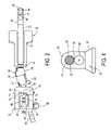
FIG. 2 is a top plan view of the shoulder mounted camera support of FIG. 1;
FIG. 3 is a side view of the shoulder mounted camera support assembly in use as a pod seated on a flat surface;
FIG. 4 is a cross-sectional view taken substantially along the plane indicated by line 44 of FIG. 1;
FIG. 5 is an enlarged, exploded side view of the shoulder mounted camera support assembly collapsed for storage or transport;
FIG. 6 is top plan view, partly in section of the camera or camcorder mount of the shoulder mounted camera support assembly; and
FIG. 7 is a view similar to FIG. 6 with a shoe connected to the camera or camcorder locked to the mount.
FIG. 8 is a side view in elevation view of the pistol grip assembly attached to the shoulder mounted camera support assembly.
DETAILED DESCRIPTION OF THE PREFERRED EMBODIMENT
Referring now to the drawings in detail, wherein like numerals indicate like elements throughout the several views in accordance with the invention. A camera or camcorder 11 can be mounted on a shoulder mounted camera support assembly 10 constituting the subject of the present invention.
FIG. 1 is a side view of the shoulder mounted camera support assembly 10 according to the present invention in use by an operator 12 where the shoulder mounted camera support assembly 10 is independently supported and stabilized on the operator's shoulder 114. The shoulder mounted camera support assembly 10 comprises a front portion to which the camera or camcorder 11 is attached and a rear portion for receipt of a battery pack 15.
FIG. 2 is a top view and FIG. 3 an enlarged side view of the camera support assembly 10 for the camera or camcorder 11. The front portion of the shoulder mounted camera support 10 has a hollow shaft 22 projecting horizontally and forwardly from a rear pivot knuckle 14, through which a flexible power cable 34 (not shown) can be threaded from a power source, such as a battery pack 15, to the camcorder or camera 11. The power cable 34 (not shown) terminates at an electrical connector 36 of the type that is well known and used in the art for ready connections to a camera or camcorder 11.
As shown in FIG. 4, extending perpendicularly from the horizontal shaft 22 is a breastplate 20 that is rotatable about a hinge 21 intermediate its length. The upper portion 23 of the breastplate 20 is mounted on the horizontal shaft 22 of the shoulder mounted camera support assembly 10 through a bushing 24 provided with a circular aperture 27 in the bushing 24 receiving the horizontal shaft 22 there through. The bushing 24 has a cam 29 mounted on opposite sides of the bushing 24 on the opposite sides of the upper portion of the breastplate 20 such that a portion of the circumference of each cam 29 seats exactly in a arced groove formed on the bottom of shaft 22 when the upper portion 23 of breastplate 20 is perpendicular to horizontal shaft 22 as shown in FIG. 4, such that the breastplate 20 can be slideably adjusted along the shaft 22, yet locked into a desired position when the bottom hinged portion 31 is extended by pivoting it about hinge 21 into contact with the chest of the operator 12 which cants the cams 29 into frictional clutching engagement with the groove 25 in the bottom of shaft 22. The breastplate 20 may be partially folded, collapsing inward from its use position illustrated in FIG. 1 and slideably adjusted at varying positions on the horizontal shaft 22 when the rear potion of the shoulder mounted camera support assembly 10 is collapsed into a pod as further described in conjunction with in FIGS. 3 and 5.
The clutched breastplate 20 extends downwardly approximately 6 inches from the bushing 24 and is arched at an angle in the middle of the breastplate 20 such that the breastplate 20 readily abuts with the operator's chest as shown in FIG. 1. The shape of the breastplate 20 allows it to be easily tilted to conform to the operator's desired fit. The breastplate 20 may comprise of any shape that safely and comfortably fits an operator's chest.
In another embodiment of the invention, the breastplate 20 may be replaced with a pistol grip 50. The pistol grip 50 is constructed with a detachable elongated firm handle 52 portion that is secured to the shoulder mounted camera support assembly 10 by appropriate securing means, for example, nuts, bolts, pins, threaded fasteners, screws or some combination thereof. The pistol grip 50 is attached to the bottom of the camera support assembly 10 by a threaded fastener 54 and a retractable locating pin 56 as seen in FIG. 8. This secures the pistol grip 50 into the preferred position for maneuvering and operating the shoulder mounted camera support assembly 10.
The pistol grip 50 is releasably attached to the shoulder mounted camera support assembly 10 and includes the circuitry to control one or more functions of the camera or camcorder 11, such as power, zooming, iris and focus among others. When attached, the pistol grip 50 assists in the maneuvering and operability of the camera or camcorder 11 which position is maintained by the counterbalance of the battery pack 15 on the rear of the shoulder mounted camera support assembly 10, positioned over the shoulder 114 and along the back of the operator 12.
The elongated firm handle 52 may be of a hollow or solid construction with a solid rectangular top portion 58 for ready annexation to the support's pivot knuckle 28. The rear portion 51 of the elongated firm handle 52 may be angled for a comfort fit, whereas the front portion 53 of the elongated firm handle 52 may be contoured with raised finger positions 55, 57 and 59 for added comfort.
The pistol grip 50 may also be attached directly to the bottom of the camera or camcorder 11 in such a manner as to preclude tipping or canting of the camera or camcorder 11 by balancing the camcorder or camera 11 on the pistol grip 50 by appropriate location of the pistol grip 50 relative to the weight of the camera 11. However, the wrist and arm of the operator 12 could become subject to fatigue, if used for an extended period of time.
The horizontal shaft 22 shown in FIG. 2 is also connected at the distal end to a front pivot knuckle 28 and may be secured to the front pivot knuckle 28 by welding, a threaded fastener or any other appropriate securing means. In the preferred embodiment, the horizontal shaft 22 is threadedly connected to the pivot knuckle 28.
The pivot knuckle 28, as with the pivot knuckle 14 has two opposed parts 42, 44 in mating engagement with each other and are connected together by a hinge 33. The opposed faces of the pivot knuckle 28 and 14 pivot on hinge 33; the only difference is that the parts 42, 44 of knuckle 14 pivot along the X-axis and parts 42, 44 pivot along a Y-axis when a pivotal latch lock 46 on rear face 44 having a hook end 47 received over a mating surface 49 on part 42 is released. This construction allows the front portion of the shoulder mounted camera support assembly 10 to swivel about an X and Y axis and collapse about the hinged knuckles 14 and 28 for ease of transportation and housing as shown in the collapsed configuration indicated in FIG. 5.
Projecting from the second part 42 of pivot knuckle 28 is a horizontal supporting shaft 70 for slideably attaching a camera or camcorder shoe and mount assembly 72 illustrated in detail in FIGS. 2 and 5. The horizontal shaft 70 is offset at a nominal angle of 16° to the axis of shaft 22 to accommodate the linear alignment of the camera's or camcorder's viewfinder 118 with the operator's eye.
A shoe and mount assembly 72 is configured for the shoe 74 to be in mating engagement with the bottom of the camera or camcorder 11. As seen in FIG. 5, the shoe 74 is detachable and is dimensioned to center fit a corresponding indent 73 in the top surface 75 of the mount 76. The shoe 74 is configured with a locating pin 78 to be placed in a an aperture (not shown) in the bottom of the camera or camcorder so as to enable a threaded connector 80 to be threadedly connected into a threaded receiving recess (not shown) in the bottom of the camera or camcorder 11. The top surface 82 of the shoe has abrasion pads 81, 83 for frictional engagement with the bottom of the camera or camcorder 11.
Once assembled to the camera or camcorder 11, the shoe 74 may be loaded into the mount 76 and is retained in position by locking means 84. The locking means 84 includes a spring-biased pin 85 held captive within a slot 87 as shown in FIGS. 6 and 7.
Pushing inward on the head 89 of pin 85 against the bias of spring 95 as shown in FIG. 6 positions an undercut or thinner diameter portion 93 of the pin 85 adjacent to the projecting cam surface 82 of shoe 74 so the shoe can be positioned wholly within recess. Release of head 89 enables a thicker beveled portion 97 of the pin shaft or body to abut a portion of downwardly angled cam surface 82 to lock the shoe against removal.
The base of the mount 76 is connected to a horizontal slide assembly 77 which is slideably mounted on bracket 88 by relatively slideable, perpendicularly oriented channel members 98,99 that are disposed on the shaft 70 of the shoulder mounted camera support assembly 10 and held in adjusted position by thumb screws 101. The mounting bracket 88 is oriented slightly off-center to shaft 70 to perfect the alignment of the camcorder's viewfinder 88 relative to the operator's eye using the sliding adjustments in the X and Y directions in a horizontal plane.
The rear portion of the shoulder mounted camera support 10 comprises of a unitary hollow shaft 18 where the power cable 34 can be directed from the battery pack 15 to the camcorder 11. The hollow shaft 18 is secured to the rear pivot knuckle 14 by welding, a threaded fastener or any other appropriate securing means. This hollow shaft 18 in this embodiment may extend downward at an angle from the rear pivot knuckle 14 to a plate 25 for ready connection to the male plate on a battery pack 15. The battery pack 15 serves as a counterbalance for the camera or camcorder 11 positioned on mounting bracket 88, so the camera or camcorder is level and parallel to the ground.
In the preferred embodiment, the male plate of the battery pack is received on a female plate 25 of the type that is shown in U.S. Pat. No. 4,810,204 to Wilson. The substantially flat male plate of the battery pack 15 has a plurality projections 103 received within slots 105 on the female plate 25 and female electrical terminals positioned within a recess for engagement with male electrical terminals on the female plate. Thus, the female and male plates of the battery pack 15 can be coupled and locked together. The assembled battery pack with plates can be attached to the rear portion of the shoulder mounted camera support assembly 10 counter-balancing the front portion of the shoulder mounted camera support assembly 10 providing independent stability without manual support.
FIG. 3 illustrates a side view of the shoulder mounted camera support assembly 10 in use on a flat surface, as a pod, or camera or camcorder support in lieu of a tripod. As seen in FIG. 3, the rear portion of the shoulder mounted camera support 10 is collapsed at the rear part 44 of the pivot knuckle 14 to create a pod that can be mounted and rotated on a flat surface 142 or attached to a one-legged support (not shown).
The rear pivot knuckle 14 has two opposed parts 42, 44 in mating engagement with each other and are connected together by hinge 33. The opposed faces of the pivot knuckle 14 when released from the latch lock 46 pivots about-hinge 33 the X-axis downwardly extending at an angle of approximately 120° between the secured and unlatched position of the latch lock 46. When the rear portion of the shoulder mounted camera support 10 is rotated open, the breastplate 20 can be partially folded, collapsing inward from the pivot hinge 21 which connects the upper and lower portions of the breastplate 20 to accommodate the extension of the rear pivot knuckle 14.

Claims (8)

1. A shoulder mounted camera support assembly for supporting a camcorder or camera comprising:
a front portion operating substantially in a horizontal plane and a rear portion that is extended from said front portion where both portions in conjunction with each other provide support for a camera or camcorder when worn on one shoulder of an operator;
said front portion comprising an angled portion such that the angled portion provides an offset with the remainder of the front portion and the rear portion in such a fashion as to compensate for the dimensional centerline of the camera relative to the centerline of the operator's shoulder;
means on said front portion for mounting a camera or camcorder;
a breastplate adjustably connected to the front portion of the shoulder mounted camera support assembly;
means for releaseably attaching a battery to the rear portion to counter-balance the front portion of the shoulder mounted camera support.
2. A shoulder mounted camera support assembly according to claim 1, wherein the rear and front portions are each constructed to pivot about a rotary axis in different planes to enable the shoulder mounted camera support assembly to be collapsed.
3. A shoulder mounted camera support assembly according to claim 1, further comprising a battery attached to the means for releaseably attaching a battery, wherein the battery and the means for releaseably attaching the battery are positioned substantially adjacent the back of the user.
4. A shoulder mounted camera support assembly according to claim 1, wherein the angled portion of the front portion is constructed to pivot in an essentially horizontal plane, and the rear portion is constructed to pivot in an essentially vertical plane.
5. A shoulder mounted camera support assembly according to claim 1, wherein said means on said front portion for mounting a camera or camcorder is slideably adjustable in at least one other axis relative to the horizontal line established by the front portion of the shoulder mounted camera support assembly.
6. A shoulder mounted camera support assembly according to claim 1, wherein a means exists on said breastplate for frictionally locking said breastplate on the front portion of the shoulder mounted camera support assembly such that the breastplate can be slid longitudinally and retained at different positions on the front portion enabling the adjustment of the shoulder mounted camera support assembly to different sized operators.
7. A shoulder mounted camera support assembly according to claim 1, wherein said means on said front portion for mounting a camera or camcorder consists of an angular block affixed to the camera and a corresponding receiving receptacle affixed to the front portion of the camera support assembly to releaseably engage the angular block thereby securing the camera to the support assembly.
8. A shoulder mounted camera support assembly for supporting a camcorder or camera comprising:
a front portion operating substantially in a horizontal plane and a rear portion that is extended from said front portion where both portions in conjunction with each other provide support for a camera or camcorder when worn on the shoulder of an operator wherein the rear portion is generally adjacent the rear shoulder/back of the user;
said front portion comprising an angled portion such that the angled portion provides an offset with the remainder of the front portion and the rear portion in such a fashion as to compensate for the dimensional centerline of the camera relative to the centerline of the operator's shoulder;
means on said front portion for mounting a camera or camcorder;
a pistol grip with an elongated handle mounted to the front portion of the shoulder mounted camera support assembly for the camera or camcorder;
means for securing said elongated handle to the front portion of the support for maneuvering the supported camera or camcorder; and
a counterbalanced weight mounted on a rear portion of the support for maintaining said support in substantially balanced level condition wherein the weight is positioned substantially adjacent the back of the user.
US10/431,912 2003-01-21 2003-05-08 Shoulder mounted support assembly to hold camera of camcorder Expired - Fee Related US6929409B2 (en)

Priority Applications (3)

Application Number Priority Date Filing Date Title
US10/431,912 US6929409B2 (en) 2003-01-21 2003-05-08 Shoulder mounted support assembly to hold camera of camcorder
US10/811,747 US7293924B2 (en) 2003-01-21 2004-03-29 Shoulder mounted support assembly to hold camera or camcorder
US11/122,542 US7318678B2 (en) 2003-01-21 2005-05-05 Self locking ergonomic support assembly for optical devices

Applications Claiming Priority (2)

Application Number Priority Date Filing Date Title
US44136503P 2003-01-21 2003-01-21
US10/431,912 US6929409B2 (en) 2003-01-21 2003-05-08 Shoulder mounted support assembly to hold camera of camcorder

Related Child Applications (1)

Application Number Title Priority Date Filing Date
US10/811,747 Continuation US7293924B2 (en) 2003-01-21 2004-03-29 Shoulder mounted support assembly to hold camera or camcorder

Publications (2)

Publication Number Publication Date
US20050117898A1 US20050117898A1 (en) 2005-06-02
US6929409B2 true US6929409B2 (en) 2005-08-16

Family

ID=32595363

Family Applications (3)

Application Number Title Priority Date Filing Date
US10/431,911 Expired - Fee Related US6779932B2 (en) 2002-06-12 2003-05-08 Shoe and mount assembly to hold camera or camcorder
US10/431,912 Expired - Fee Related US6929409B2 (en) 2003-01-21 2003-05-08 Shoulder mounted support assembly to hold camera of camcorder
US10/811,747 Expired - Fee Related US7293924B2 (en) 2003-01-21 2004-03-29 Shoulder mounted support assembly to hold camera or camcorder

Family Applications Before (1)

Application Number Title Priority Date Filing Date
US10/431,911 Expired - Fee Related US6779932B2 (en) 2002-06-12 2003-05-08 Shoe and mount assembly to hold camera or camcorder

Family Applications After (1)

Application Number Title Priority Date Filing Date
US10/811,747 Expired - Fee Related US7293924B2 (en) 2003-01-21 2004-03-29 Shoulder mounted support assembly to hold camera or camcorder

Country Status (3)

Country Link
US (3) US6779932B2 (en)
EP (2) EP1441169A3 (en)
JP (2) JP2004226959A (en)

Cited By (10)

* Cited by examiner, † Cited by third party
Publication number Priority date Publication date Assignee Title
US20040212788A1 (en) * 2003-01-21 2004-10-28 Anton/Bauer, Inc. Shoulder mounted support assembly to hold camera or camcorder
US20050201744A1 (en) * 2003-01-21 2005-09-15 Anton/Bauer, Inc. Self locking ergonomic support assembly for optical devices
US7703995B1 (en) 2007-04-05 2010-04-27 Aneesh Sivan Ergonomic apparatus for stabilizing support of portable video devices
US8657507B2 (en) 2011-10-17 2014-02-25 The Alba Group, Ltd. System for camera stabilization
US8985878B2 (en) 2011-10-17 2015-03-24 The Alba Group, Ltd. System for camera stabilization
US9143661B2 (en) 2013-07-29 2015-09-22 Leslie A. Pock Balanced modular camera mount apparatus and method of use
US9140962B2 (en) 2013-11-19 2015-09-22 Brent WILLIAMS Graham Camera mount
AU2015201658B2 (en) * 2006-01-06 2017-01-05 Abreu, Marcio Marc Aurelio Martins MR A wearable electronic system and support structure for a wearable electronic device
US10073323B2 (en) 2013-03-15 2018-09-11 Enrique LAUNI Holder for a mobile device to capture images
US11552365B2 (en) 2020-08-31 2023-01-10 Techtronic Cordless Gp Tripod system

Families Citing this family (37)

* Cited by examiner, † Cited by third party
Publication number Priority date Publication date Assignee Title
JP2003072059A (en) * 2001-06-21 2003-03-12 Ricoh Co Ltd Inkjet recorder and duplicator
US20050162122A1 (en) * 2004-01-22 2005-07-28 Dunn Glenn M. Fuel cell power and management system, and technique for controlling and/or operating same
US7864244B2 (en) * 2005-09-09 2011-01-04 Anton/Bauer, Inc. Camera system and power supply for optical recording devices
US7724303B2 (en) * 2005-09-09 2010-05-25 Anton/Bauer, Inc. Camera system and power supply for optical recording devices
US7412753B2 (en) * 2005-09-16 2008-08-19 Honda Motor Co., Ltd. Pin apparatuses and methods
US7775201B2 (en) * 2005-10-11 2010-08-17 Hoyt Archery, Inc. Attachment apparatus and method
US20070164987A1 (en) * 2006-01-17 2007-07-19 Christopher Graham Apparatus for hands-free support of a device in front of a user's body
CN100418008C (en) * 2006-06-14 2008-09-10 威宝摄影器材有限公司 Connection locking device for tray and head of photographic/camera tripod
CN100460991C (en) * 2006-08-22 2009-02-11 威宝摄影器材有限公司 Quick connector for camera with head
US8087315B2 (en) * 2006-10-10 2012-01-03 Honeywell International Inc. Methods and systems for attaching and detaching a payload device to and from, respectively, a gimbal system without requiring use of a mechanical tool
GB2459303B (en) * 2008-04-18 2013-01-09 Peter John Taylor Apparatus for support and movement of a camera
KR101018317B1 (en) 2009-04-27 2011-03-04 박은락 A digital camera support apparatus for operating remotely a shutter button of a digital camera
US8804030B2 (en) 2010-04-08 2014-08-12 Anton/Bauer, Inc. Camera system and power supply for optical recording devices
CN102346360A (en) * 2010-08-05 2012-02-08 罗劲 Auxiliary frame for image shooting
JP5553942B2 (en) * 2010-08-27 2014-07-23 中山立信撮影器材有限公司 Pan head locking device, adjusting device and panel device
JP4778110B2 (en) * 2010-11-22 2011-09-21 真太郎 菅原 Tools and systems for fixing mobile devices with video recording functions such as video cameras or smartphones to the shoulders and flat surfaces
WO2013030813A2 (en) * 2011-09-02 2013-03-07 Invue Security Products Inc. Camera sensor having reversible sensor housing and reversible adapter
US8827219B2 (en) 2011-12-09 2014-09-09 Kessler Crane, Inc. Quick release plate
KR101391509B1 (en) * 2012-08-27 2014-05-07 한국수력원자력 주식회사 Remote attaching and detaching device including cell camera
US9360739B2 (en) * 2012-11-30 2016-06-07 David Fliger Photographic and video mounting plate with deployable attachment point
US8727642B1 (en) 2013-03-11 2014-05-20 Wilson Tse Quick-release camera mounting system
US8774618B1 (en) * 2013-10-04 2014-07-08 Michael Muzila Adjustable camera flash mounting device
EP3054814A4 (en) 2013-10-08 2016-09-21 Invue Security Products Inc Quick release sensor for merchandise display
US9625790B2 (en) * 2014-09-28 2017-04-18 Larry J. Tiefenbrunn Support base for photographic apparatus
KR102339142B1 (en) * 2015-03-02 2021-12-15 최해용 A Support Bar for a Virtual Reality Camera
US20160363262A1 (en) * 2015-06-10 2016-12-15 Connor Moelmann Mounting Device
US9746751B1 (en) * 2016-03-31 2017-08-29 Yudah Amit Camera mount system
JP6920146B2 (en) * 2017-09-08 2021-08-18 株式会社東京建設コンサルタント A pedestal device suitable for installing equipment for observing river flow conditions on bridge railings
CN207588135U (en) * 2017-10-23 2018-07-06 深圳市大疆灵眸科技有限公司 Connector and remote control
US10260677B1 (en) 2018-03-05 2019-04-16 Panavision International, L.P. Adjustable shoulder rest for camera
US10310249B1 (en) * 2019-01-05 2019-06-04 Ephraim Blu Bentley Binocular adaptor assembly
US10684462B1 (en) * 2019-01-05 2020-06-16 Ephraim Blu Bentley Binocular adaptor assembly
KR102189500B1 (en) * 2019-02-11 2020-12-11 주식회사 상화 Augmented Reality Experience Apparatus
US10782596B2 (en) * 2019-05-20 2020-09-22 Jeffrey Overall Rotation activated quick-release system
DE102019120702A1 (en) * 2019-07-31 2021-02-04 Navvis Gmbh Frame for at least one scanning device and space detection device with at least one scanning device
WO2021022393A1 (en) * 2019-08-02 2021-02-11 深圳市大疆创新科技有限公司 Handheld gimbal
USD967244S1 (en) * 2020-11-04 2022-10-18 The F.J. Westcott Company Bipod/tripod mounting plate for video/photography equipment

Citations (8)

* Cited by examiner, † Cited by third party
Publication number Priority date Publication date Assignee Title
US2873645A (en) * 1957-05-23 1959-02-17 William A Horton Portable sound recording moving picture apparatus
US4244500A (en) * 1979-06-18 1981-01-13 Raymond Fournier Viewing support
US4437753A (en) * 1981-10-09 1984-03-20 Dunn Robert E Apparatus for supporting a camera against the sternum of the photographer
US4943820A (en) * 1989-10-13 1990-07-24 Larock Warren D Portable camera support
US4963904A (en) * 1989-09-19 1990-10-16 Chun Mao Lee Portable camera support assembly
US5612756A (en) * 1995-11-13 1997-03-18 Lionshead Publishing Ltd. Support for video camera
US5890025A (en) 1997-06-03 1999-03-30 Hart Productions, Inc. Frame assembly for supporting a camera
US6056449A (en) 1997-06-03 2000-05-02 Hart Productions, Inc. Frame assembly for supporting a camera

Family Cites Families (25)

* Cited by examiner, † Cited by third party
Publication number Priority date Publication date Assignee Title
US2636822A (en) 1950-03-08 1953-04-28 Kathryn B Anderson Device for supporting a camera or similar instrument
US3109617A (en) * 1960-08-22 1963-11-05 Peter R Meyer Device for mounting cameras on tripods
US3490724A (en) * 1967-09-01 1970-01-20 Kichitaro Ichikawa Three-legged stand
US3612462A (en) * 1969-08-26 1971-10-12 Quick Set Inc Instrument mount assembly
US3767095A (en) 1971-06-18 1973-10-23 R Jones Camera supporting harness
US4509795A (en) * 1982-09-09 1985-04-09 Ptc Aerospace Inc. Self-deploying legrest assembly
DE3308509C1 (en) * 1983-03-10 1984-08-16 Hermann 8500 Nürnberg Knaudt Shoulder-hand tripod for photographic devices
FR2611855B1 (en) 1987-03-03 1989-07-13 Spianti Dany PORTABLE EQUIPMENT SUPPORT, ESPECIALLY CAMERA
US4810204A (en) 1987-03-26 1989-03-07 Anton/Bauer, Inc. Battery pack connection
US4727390A (en) * 1987-06-22 1988-02-23 Brown Melvin W Camera mounting bracket
JPS6440792A (en) * 1987-08-07 1989-02-13 Nippon Velbon Seiki Kogyo Universal head
DE8913880U1 (en) * 1989-11-24 1990-01-11 Kuerbi & Niggeloh Bilora Gmbh, 5608 Radevormwald, De
US5294947A (en) 1991-12-30 1994-03-15 Harrington Paul B Body mounted camera support
US5260731A (en) 1992-01-13 1993-11-09 Baker Jr Roy E Camera mount for a vehicle
DE9212708U1 (en) 1992-09-15 1992-12-10 Haehnel Foto Industries Ltd., Bandon, Ie
DE4230856A1 (en) * 1992-09-15 1994-03-17 Kuerbi & Niggeloh Bilora Gmbh Shoulder support for film or video camera - has pivoted handgrip adjusted to allow shoulder support to act as tripod support
IL108605A0 (en) * 1994-02-09 1995-03-15 Israel State Quick connector
DE29512256U1 (en) * 1995-07-29 1995-10-05 Yang Oliver Camera support device
GB2306295B (en) 1995-10-24 1999-07-14 David Slinger Optical instrument support
US5940644A (en) 1998-04-22 1999-08-17 Putora; Ivan Balancing apparatus for stabilizing camera movement
US6234690B1 (en) * 1998-08-20 2001-05-22 Frank Lemieux Camera quick-release device
US6119398A (en) 1998-11-05 2000-09-19 Yates, Jr.; H. Dale Tilt window balance shoe assembly with three directional locking
US6530702B2 (en) 2000-12-02 2003-03-11 Thomas H. S. Harris Operator supported remote camera positioning and control system
US6601999B1 (en) 2002-04-11 2003-08-05 Thomas S. McTeer Video camera bracket
US6779932B2 (en) 2002-06-12 2004-08-24 Anton/Bauer, Inc. Shoe and mount assembly to hold camera or camcorder

Patent Citations (8)

* Cited by examiner, † Cited by third party
Publication number Priority date Publication date Assignee Title
US2873645A (en) * 1957-05-23 1959-02-17 William A Horton Portable sound recording moving picture apparatus
US4244500A (en) * 1979-06-18 1981-01-13 Raymond Fournier Viewing support
US4437753A (en) * 1981-10-09 1984-03-20 Dunn Robert E Apparatus for supporting a camera against the sternum of the photographer
US4963904A (en) * 1989-09-19 1990-10-16 Chun Mao Lee Portable camera support assembly
US4943820A (en) * 1989-10-13 1990-07-24 Larock Warren D Portable camera support
US5612756A (en) * 1995-11-13 1997-03-18 Lionshead Publishing Ltd. Support for video camera
US5890025A (en) 1997-06-03 1999-03-30 Hart Productions, Inc. Frame assembly for supporting a camera
US6056449A (en) 1997-06-03 2000-05-02 Hart Productions, Inc. Frame assembly for supporting a camera

Cited By (14)

* Cited by examiner, † Cited by third party
Publication number Priority date Publication date Assignee Title
US20040212788A1 (en) * 2003-01-21 2004-10-28 Anton/Bauer, Inc. Shoulder mounted support assembly to hold camera or camcorder
US20050201744A1 (en) * 2003-01-21 2005-09-15 Anton/Bauer, Inc. Self locking ergonomic support assembly for optical devices
US7293924B2 (en) 2003-01-21 2007-11-13 Anton/Bauer, Inc. Shoulder mounted support assembly to hold camera or camcorder
US7318678B2 (en) * 2003-01-21 2008-01-15 Anton/Bauer, Inc. Self locking ergonomic support assembly for optical devices
AU2015201658B2 (en) * 2006-01-06 2017-01-05 Abreu, Marcio Marc Aurelio Martins MR A wearable electronic system and support structure for a wearable electronic device
US7703995B1 (en) 2007-04-05 2010-04-27 Aneesh Sivan Ergonomic apparatus for stabilizing support of portable video devices
US8985878B2 (en) 2011-10-17 2015-03-24 The Alba Group, Ltd. System for camera stabilization
US8657507B2 (en) 2011-10-17 2014-02-25 The Alba Group, Ltd. System for camera stabilization
US10073323B2 (en) 2013-03-15 2018-09-11 Enrique LAUNI Holder for a mobile device to capture images
US9143661B2 (en) 2013-07-29 2015-09-22 Leslie A. Pock Balanced modular camera mount apparatus and method of use
US9140962B2 (en) 2013-11-19 2015-09-22 Brent WILLIAMS Graham Camera mount
US9482932B2 (en) 2013-11-19 2016-11-01 Brent WILLIAMS Graham Camera mount
US11552365B2 (en) 2020-08-31 2023-01-10 Techtronic Cordless Gp Tripod system
US11870086B2 (en) 2020-08-31 2024-01-09 Techtronic Cordless Gp Tripod system

Also Published As

Publication number Publication date
US20050117898A1 (en) 2005-06-02
US6779932B2 (en) 2004-08-24
JP2004226959A (en) 2004-08-12
US7293924B2 (en) 2007-11-13
JP2004229274A (en) 2004-08-12
US20040212788A1 (en) 2004-10-28
US20040146293A1 (en) 2004-07-29
EP1441170A2 (en) 2004-07-28
EP1441170A3 (en) 2005-01-12
EP1441169A2 (en) 2004-07-28
EP1441169A3 (en) 2005-01-12
JP4204436B2 (en) 2009-01-07

Similar Documents

Publication Publication Date Title
US6929409B2 (en) Shoulder mounted support assembly to hold camera of camcorder
US7318678B2 (en) Self locking ergonomic support assembly for optical devices
US5098182A (en) Stabilized equipment support, primarily for use with light-weight cameras
JP2798277B2 (en) Device support, handle for device support, recording method of stabilized image, and stabilized recorded image by the recording method
AU2010203242B2 (en) Stabilized equipment support and method of balancing same
US6764231B1 (en) Body mounted camera support
US9182654B2 (en) Hand held camera mount
US7922401B2 (en) Camera rig with center-of-gravity correction system
US8029197B2 (en) Hand-held image stabilization and balancing system for cameras
US6272785B1 (en) Gun holder
US6056449A (en) Frame assembly for supporting a camera
CA2913369A1 (en) Mount for a camera to be carried on a body-supported computer
WO2018192082A1 (en) Cradle head bracket
US6862407B2 (en) Camera stabilizer platform and camcorder therefor
US20080310834A1 (en) Camera Holding Device
GB2437361A (en) Camera support device
CN109891145B (en) Switching device and hand-held ring equipment
US7488126B2 (en) Camera stabilizer
US7097368B2 (en) Camera stabilizer
WO2004098483A2 (en) Chest-mounted support apparatus
WO2008013503A1 (en) Dual-function body support for a tripod
JPH0411421Y2 (en)

Legal Events

Date Code Title Description
AS Assignment

Owner name: ANTON/BAUER, INC., CONNECTICUT

Free format text: ASSIGNMENT OF ASSIGNORS INTEREST;ASSIGNORS:DESORBO, ALEXANDER P.;HULTMAN, CARL A.;TEODOSIO, JOSEPH T.;REEL/FRAME:014061/0024

Effective date: 20030430

CC Certificate of correction
FEPP Fee payment procedure

Free format text: PAT HOLDER NO LONGER CLAIMS SMALL ENTITY STATUS, ENTITY STATUS SET TO UNDISCOUNTED (ORIGINAL EVENT CODE: STOL); ENTITY STATUS OF PATENT OWNER: LARGE ENTITY

FPAY Fee payment

Year of fee payment: 4

REMI Maintenance fee reminder mailed
LAPS Lapse for failure to pay maintenance fees

Free format text: PATENT EXPIRED FOR FAILURE TO PAY MAINTENANCE FEES (ORIGINAL EVENT CODE: EXP.)

FP Lapsed due to failure to pay maintenance fee

Effective date: 20130816

STCH Information on status: patent discontinuation

Free format text: PATENT EXPIRED DUE TO NONPAYMENT OF MAINTENANCE FEES UNDER 37 CFR 1.362