US6923148B2 - Combustion chamber with high temperature protective coating - Google Patents
Combustion chamber with high temperature protective coating Download PDFInfo
- Publication number
- US6923148B2 US6923148B2 US10/947,153 US94715304A US6923148B2 US 6923148 B2 US6923148 B2 US 6923148B2 US 94715304 A US94715304 A US 94715304A US 6923148 B2 US6923148 B2 US 6923148B2
- Authority
- US
- United States
- Prior art keywords
- combustion chamber
- bottom wall
- inner tank
- floor shield
- hot water
- Prior art date
- Legal status (The legal status is an assumption and is not a legal conclusion. Google has not performed a legal analysis and makes no representation as to the accuracy of the status listed.)
- Expired - Lifetime
Links
- 238000002485 combustion reaction Methods 0.000 title claims abstract description 46
- 239000011253 protective coating Substances 0.000 title description 3
- XLYOFNOQVPJJNP-UHFFFAOYSA-N water Substances O XLYOFNOQVPJJNP-UHFFFAOYSA-N 0.000 claims abstract description 17
- 239000003973 paint Substances 0.000 claims abstract description 8
- 238000000576 coating method Methods 0.000 claims description 7
- 239000011248 coating agent Substances 0.000 claims description 6
- 239000000919 ceramic Substances 0.000 claims description 5
- 239000000654 additive Substances 0.000 claims description 2
- 230000000996 additive effect Effects 0.000 claims description 2
- 239000000853 adhesive Substances 0.000 claims description 2
- 230000001070 adhesive effect Effects 0.000 claims description 2
- 239000003570 air Substances 0.000 description 8
- 229910000831 Steel Inorganic materials 0.000 description 7
- 239000010959 steel Substances 0.000 description 7
- 239000007789 gas Substances 0.000 description 5
- 238000012986 modification Methods 0.000 description 2
- 230000004048 modification Effects 0.000 description 2
- 239000012080 ambient air Substances 0.000 description 1
- 239000010960 cold rolled steel Substances 0.000 description 1
- 239000006261 foam material Substances 0.000 description 1
- 239000003517 fume Substances 0.000 description 1
- 239000002184 metal Substances 0.000 description 1
Images

Classifications
-
- F—MECHANICAL ENGINEERING; LIGHTING; HEATING; WEAPONS; BLASTING
- F23—COMBUSTION APPARATUS; COMBUSTION PROCESSES
- F23M—CASINGS, LININGS, WALLS OR DOORS SPECIALLY ADAPTED FOR COMBUSTION CHAMBERS, e.g. FIREBRIDGES; DEVICES FOR DEFLECTING AIR, FLAMES OR COMBUSTION PRODUCTS IN COMBUSTION CHAMBERS; SAFETY ARRANGEMENTS SPECIALLY ADAPTED FOR COMBUSTION APPARATUS; DETAILS OF COMBUSTION CHAMBERS, NOT OTHERWISE PROVIDED FOR
- F23M5/00—Casings; Linings; Walls
-
- F—MECHANICAL ENGINEERING; LIGHTING; HEATING; WEAPONS; BLASTING
- F23—COMBUSTION APPARATUS; COMBUSTION PROCESSES
- F23M—CASINGS, LININGS, WALLS OR DOORS SPECIALLY ADAPTED FOR COMBUSTION CHAMBERS, e.g. FIREBRIDGES; DEVICES FOR DEFLECTING AIR, FLAMES OR COMBUSTION PRODUCTS IN COMBUSTION CHAMBERS; SAFETY ARRANGEMENTS SPECIALLY ADAPTED FOR COMBUSTION APPARATUS; DETAILS OF COMBUSTION CHAMBERS, NOT OTHERWISE PROVIDED FOR
- F23M2900/00—Special features of, or arrangements for combustion chambers
- F23M2900/05004—Special materials for walls or lining
-
- F—MECHANICAL ENGINEERING; LIGHTING; HEATING; WEAPONS; BLASTING
- F24—HEATING; RANGES; VENTILATING
- F24H—FLUID HEATERS, e.g. WATER OR AIR HEATERS, HAVING HEAT-GENERATING MEANS, e.g. HEAT PUMPS, IN GENERAL
- F24H1/00—Water heaters, e.g. boilers, continuous-flow heaters or water-storage heaters
- F24H1/18—Water-storage heaters
- F24H1/20—Water-storage heaters with immersed heating elements, e.g. electric elements or furnace tubes
- F24H1/205—Water-storage heaters with immersed heating elements, e.g. electric elements or furnace tubes with furnace tubes
Definitions
- the present invention relates to a combustion chamber for a gas-fired hot water heater and wherein the circumferential wall and the bottom wall of a combustion chamber are provided with a high temperature protective coating.
- Combustion chambers of gas-fired hot water heaters are constructed below the bottom wall of the inner tank which contains water to be heated.
- a flue normally extends centrally in the inner tank from the bottom wall.
- the combustion chamber if formed by a circumferential skirt or wall disposed below the lower tank and a bottom wall which is elevated from a floor support surface of the hot water heater by a bottom pan.
- the side walls and bottom wall of the combustion chamber are usually constructed from hot or cold rolled steel which is very thin. This steel is usually treated to remove scales and often this steel is not of uniform thickness. Due to the poor quality of this steel and the thickness thereof, there is excessive heat loss through the side wall and bottom wall of the combustion chamber and this reduces the efficiency of the hot water heater.
- a combustion chamber for a gas-fired hot water heater which comprises a top wall which is defined by a bottom wall of an inner tank.
- a flue extends through the inner tank bottom wall.
- a circumferential skirt is disposed about the combustion chamber.
- the combustion chamber is supported elevated from a support surface by a bottom pan assembly of a hot water heater housing.
- a combustion air inlet means leads to the combustion chamber.
- a floor shield is supported above the bottom wall and spaced below a gas burner assembly.
- the circumferential skirt and/or the floor shield are coated on at least one surface thereof with refractory paint to reflect radiant heat inwardly in the combustion chamber whereby to maximize heat transferred to the inner tank and to minimize heat loss through the skirt and floor shield.
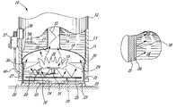
- FIG. 1 is a transverse, partly fragmented and partly sectioned view showing the combustion chamber of the present invention
- FIG. 2 is an enlarged, cross section view through the circumferential side wall or floor shield of the hot water heater showing the coating in a surface of the steel plate.
- the hot water heater has an inner tank 11 and an outer casing 12 spaced therefrom to define an insulating space 13 in which an insulating foam material is injected.
- the inner tank 11 has a central flue 14 provided with a baffle 15 and through which hot exhaust fumes from the combustion chamber 16 are convected.
- the water 17 in the inner tank 11 is heated by heat transfer through its bottom wall 18 and through the sidewall 14 ′ of the flue 14 .
- the combustion chamber is provided with a burner assembly 19 which is supported elevated from a bottom wall 20 of the combustion chamber.
- the skirt or side wall 21 of the combustion chamber is formed by a steel cylinder which is very thin and which is hot or cold rolled.
- the bottom wall 20 is formed of such steel.
- the bottom wall 20 is supported elevated by a bottom pan assembly 22 and air openings 23 are provided about the pan whereby to admit ambient air into the inlet opening 24 formed in the bottom wall 20 to provide combustion air to the burner assembly 19 .
- the combustion chamber may be fed combustible air through other means such as a snorkel pipe (not shown) disposed vertically along the hot water heater and extending through the side wall 21 of the combustion chamber.
- a floor shield 25 is supported elevated above the air opening 24 whereby to protect the floor 26 from radiant heat from the combustion chamber.
- the floor shield 25 is spaced from the side wall 21 whereby to provide a circumferential channel 27 so that combustible air can enter into the combustion chamber 16 .
- the circumferential skirt or sidewall 21 and/or the floor shield 25 are coated, on at least one of two surfaces thereof, with a refractory paint 29 whereby to reflect radiant heat inwardly in the combustion chamber as indicated by arrows 30 to maximize heat transfer to the inner tank towards its bottom wall and to minimize heat loss through the skirt and floor shield.
- a refractory paint 29 whereby to reflect radiant heat inwardly in the combustion chamber as indicated by arrows 30 to maximize heat transfer to the inner tank towards its bottom wall and to minimize heat loss through the skirt and floor shield.
- the coating is on the inside surface facing the combustion chamber 16 .
- This refractory paint can be a ceramic adhesive coating such as the coating #840-M sold by Aremco Products Inc. or a ceramic additive such as that provided by Hy-Tech Thermal Solutions. Of course, other types of heat resistant ceramic or reflective coatings may serve the purpose.
- Another advantage of coating the side wall and bottom wall as well as the floor shield of the combustion chamber with such high temperature protective coatings is to extend the life of the combustion chamber as these metal parts are usually formed from very thin gauge steel plates and because of their non-uniform thickness some of these can deteriorate quite quickly. They should have a life span which as least extends that of the gas-water heater and it is usually recommended that these be changed every 9-10 years.
- FIG. 1 illustrates component parts associated with the burner assembly 19 and namely a gas burner 35 , a pilot ignition device 36 , a gas control device 37 and a spark ignition system 38 .
- a temperature sensor 39 extends inside the inner tank to sense the temperature therein and a control device controls the supply of gas through the supply line 40 to the gas burner 35 .
Landscapes
- Engineering & Computer Science (AREA)
- Chemical & Material Sciences (AREA)
- Combustion & Propulsion (AREA)
- Mechanical Engineering (AREA)
- General Engineering & Computer Science (AREA)
Abstract
Description
Claims (4)
Applications Claiming Priority (2)
| Application Number | Priority Date | Filing Date | Title |
|---|---|---|---|
| CA2,442,450 | 2003-09-25 | ||
| CA2442450A CA2442450C (en) | 2003-09-25 | 2003-09-25 | Combustion chamber with high temperature protective coating |
Publications (2)
| Publication Number | Publication Date |
|---|---|
| US20050066913A1 US20050066913A1 (en) | 2005-03-31 |
| US6923148B2 true US6923148B2 (en) | 2005-08-02 |
Family
ID=34318777
Family Applications (1)
| Application Number | Title | Priority Date | Filing Date |
|---|---|---|---|
| US10/947,153 Expired - Lifetime US6923148B2 (en) | 2003-09-25 | 2004-09-23 | Combustion chamber with high temperature protective coating |
Country Status (2)
| Country | Link |
|---|---|
| US (1) | US6923148B2 (en) |
| CA (1) | CA2442450C (en) |
Citations (4)
| Publication number | Priority date | Publication date | Assignee | Title |
|---|---|---|---|---|
| US6202935B1 (en) * | 1998-04-15 | 2001-03-20 | Aos Holding Company | Combined potable water heater and hydronic heating system |
| US6418884B1 (en) * | 2001-10-15 | 2002-07-16 | Rheem Manufacturing Company | Fuel-fired heating appliance having flame arrestor plate with associated scale deflector shield |
| US6698385B1 (en) * | 2003-01-29 | 2004-03-02 | Giant Factories Inc. | Combustion chamber shield for hot water heaters |
| US6725811B1 (en) * | 1993-08-27 | 2004-04-27 | American Water Heater Company | Water heater with low NOx fiber matrix burner |
-
2003
- 2003-09-25 CA CA2442450A patent/CA2442450C/en not_active Expired - Fee Related
-
2004
- 2004-09-23 US US10/947,153 patent/US6923148B2/en not_active Expired - Lifetime
Patent Citations (4)
| Publication number | Priority date | Publication date | Assignee | Title |
|---|---|---|---|---|
| US6725811B1 (en) * | 1993-08-27 | 2004-04-27 | American Water Heater Company | Water heater with low NOx fiber matrix burner |
| US6202935B1 (en) * | 1998-04-15 | 2001-03-20 | Aos Holding Company | Combined potable water heater and hydronic heating system |
| US6418884B1 (en) * | 2001-10-15 | 2002-07-16 | Rheem Manufacturing Company | Fuel-fired heating appliance having flame arrestor plate with associated scale deflector shield |
| US6698385B1 (en) * | 2003-01-29 | 2004-03-02 | Giant Factories Inc. | Combustion chamber shield for hot water heaters |
Also Published As
| Publication number | Publication date |
|---|---|
| CA2442450A1 (en) | 2005-03-25 |
| CA2442450C (en) | 2011-04-26 |
| US20050066913A1 (en) | 2005-03-31 |
Similar Documents
| Publication | Publication Date | Title |
|---|---|---|
| US7063528B2 (en) | Radiant tube and convection oven | |
| US6725811B1 (en) | Water heater with low NOx fiber matrix burner | |
| CA2359395A1 (en) | Fuel-fired heating appliance with combustion chamber temperature-sensing combustion air shutoff system | |
| US6279349B1 (en) | Method for making glass sheet heating furnace | |
| US5816199A (en) | High efficiency water heater | |
| US5305954A (en) | Heating systems | |
| MXPA05006274A (en) | Water heater with normally closed air inlet damper. | |
| US6923148B2 (en) | Combustion chamber with high temperature protective coating | |
| US6698385B1 (en) | Combustion chamber shield for hot water heaters | |
| US6766771B1 (en) | Fuel-fired water heater with dual function combustion cutoff switch in its draft structure | |
| US6418884B1 (en) | Fuel-fired heating appliance having flame arrestor plate with associated scale deflector shield | |
| US20020157659A1 (en) | Gas broiler | |
| DE50309895D1 (en) | BURNERS, ESPECIALLY VENTURIBRENNER, WITH A COMBUSTIBLE TUBE | |
| JPH08247437A (en) | Exhaust structure for gas direct fire type oven | |
| CN113531529A (en) | Burner for stove and gas stove | |
| CN111981521A (en) | a vegetable oil stove | |
| US776053A (en) | Solid and fluid fuel furnace. | |
| US10520221B2 (en) | Refractory for heating system | |
| KR200235055Y1 (en) | Metal smelting furnace for brown gas | |
| US20240175603A1 (en) | Blower Collar for Combustion System | |
| JP2002234768A (en) | Firing furnace | |
| JP3293284B2 (en) | Combustion equipment | |
| JPS60240907A (en) | Radiant tube burner | |
| JP3153031U (en) | Infrared burner for top fire | |
| CA2417551C (en) | Combustion chamber shield for hot water heaters |
Legal Events
| Date | Code | Title | Description |
|---|---|---|---|
| AS | Assignment |
Owner name: GIANT FACTORIES INC., CANADA Free format text: ASSIGNMENT OF ASSIGNORS INTEREST;ASSIGNOR:LESAGE, CLAUDE;REEL/FRAME:015828/0883 Effective date: 20040914 |
|
| STCF | Information on status: patent grant |
Free format text: PATENTED CASE |
|
| FPAY | Fee payment |
Year of fee payment: 4 |
|
| FPAY | Fee payment |
Year of fee payment: 8 |
|
| FPAY | Fee payment |
Year of fee payment: 12 |
|
| AS | Assignment |
Owner name: A. O. SMITH ENTERPRISES LTD., CANADA Free format text: MERGER;ASSIGNOR:USINES GIANT INC.;REEL/FRAME:068622/0455 Effective date: 20231220 |
|
| AS | Assignment |
Owner name: A. O. SMITH ENTERPRISES LTD., CANADA Free format text: CORRECTIVE ASSIGNMENT TO CORRECT THE ASSIGNOR NAME PREVIOUSLY RECORDED ON REEL 68622 FRAME 455. ASSIGNOR(S) HEREBY CONFIRMS THE MERGER;ASSIGNOR:GIANT FACTORIES INC.;REEL/FRAME:069310/0569 Effective date: 20231220 |