US6915534B1 - Insulated cover and method for using same - Google Patents
Insulated cover and method for using same Download PDFInfo
- Publication number
- US6915534B1 US6915534B1 US10/687,008 US68700803A US6915534B1 US 6915534 B1 US6915534 B1 US 6915534B1 US 68700803 A US68700803 A US 68700803A US 6915534 B1 US6915534 B1 US 6915534B1
- Authority
- US
- United States
- Prior art keywords
- blanket
- panels
- panel
- lateral
- lateral layers
- Prior art date
- Legal status (The legal status is an assumption and is not a legal conclusion. Google has not performed a legal analysis and makes no representation as to the accuracy of the status listed.)
- Expired - Lifetime
Links
Images


Classifications
-
- E—FIXED CONSTRUCTIONS
- E04—BUILDING
- E04H—BUILDINGS OR LIKE STRUCTURES FOR PARTICULAR PURPOSES; SWIMMING OR SPLASH BATHS OR POOLS; MASTS; FENCING; TENTS OR CANOPIES, IN GENERAL
- E04H4/00—Swimming or splash baths or pools
- E04H4/06—Safety devices; Coverings for baths
- E04H4/08—Coverings consisting of rigid elements, e.g. coverings composed of separate or connected elements
Definitions
- the present invention relates to an insulated cover and method for using same.
- Insulated covers have been used over swimming pools to maintain the temperature of the pool overnight or during cool seasons.
- Other insulated covers have been provided over lagoons or pools which are used for digesting sludge and other contaminates for waste materials. In these lagoons it is desirable to provide a cover over the lagoon so as to maintain an appropriate temperature within the lagoon to enable bacteria to decompose the materials and solution in the lagoon.
- U.S. Pat. No. 5,546,615 illustrates a cover which is comprised of a plurality of panels that are joined together at their edges. The panels are joined by cables extending through grommets in the lateral sides of each panel. These cables require anchoring in the ground along the edges of the pool or lagoon, and such anchoring requires the formation of concrete anchors having eyelets for receiving the cables and tying the cables. The cables extending through the grommets to join the various panels together are rough and are time consuming to fasten and tie.
- a primary object of the present invention is the provision of an improved insulated cover and method for using same.
- a further object of the present invention is the provision of an improved insulated cover and method for using same which welds the adjacent lateral edges of the panels together to form a blanket.
- a further object of the present invention is the provision of an improved insulated cover and method for using same wherein the lateral edges of the panels are overlapped and are heat sealed in the interface between the overlapping edges in addition to the formation of a weld at the overlapping edges.
- a further object of the present invention is the provision of an improved insulated cover and method for using same which includes holes between the various insulated panels for permitting water to drain downwardly from the upper surface of the blanket to the lower surface of the blanket and also for permitting gasses to escape from beneath the lower surface of the blanket to the upper surface of the blanket.
- a further object of the present invention is the provision of an insulated cover and method for using same which includes parametric edges extending around a blanket, the parametric edges being embedded within trenches around the perimeter of the lagoon or pool, and with dirt being packed over the embedded edges within the trenches so as to anchor the edges of the blanket.
- a further object of the present invention is the provision of an improved insulated cover and method for using same which is economical to manufacture, durable in use, and efficient in operation.
- a cover for a pool having a pool basin, a quantity of fluid within the pool basin, and a soil surrounding the pool basin.
- the cover includes a plurality of panels, each having an upper layer, a lower layer, and an insulation material sandwiched between the upper layer and the lower layer.
- the panels each have a lateral layer extending laterally from the sandwiched insulation material.
- Each of the lateral layers includes an upper surface and a lower surface.
- Each of the plurality of panels has pairs of the lateral layers welded to one another to form a singular blanket from the plurality of panels.
- the blanket is in covering relation over the fluid within the pool basin.
- a plurality of holes formed in the lateral layers permit water to drain through the holes from above the blanket to below the blanket. These holes also permit gasses to rise from the fluid within the pool basin upwardly through the holes to above the blanket.
- pool is utilized with respect to this invention. This term is intended to include any type of swimming pool, lagoon, or other pool which requires insulated covers for maintaining the temperature of the fluid during cold weather.
- lagoons used for holding waste fluids for decomposing.
- the pairs of lateral layers are welded together and each comprise an overlapped portion comprising an upper surface of one of the lateral layers in each of the pairs in contact with the lower surface of the other of the lateral layers in each of the pairs.
- a weld joint overlies and contacts a portion of the upper surface of one of the lateral layers in each of the pairs and overlying and contacting a portion of the upper surface of the other of the lateral layers in each of the pairs.
- the overlapping upper surface of one of the lateral layers within each of the pairs and the lower surface of the other of the lateral layers within each of the pairs are heat sealed together.
- the blanket includes a perimeter edge extending there around.
- the perimeter edge is anchored to the soil surrounding the pool basin.
- the perimeter edge of the blanket is at least partially within a trench surrounding the lagoon, and a quantity of soil is in the trench to anchor the perimeter edge of the blanket.
- the method of the present invention comprises overlapping the lateral layers of a first panel and a second panel of the plurality of panels so that an interface portion on the lower surface on one of the lateral layers contacts an interface portion of the upper surface of an adjacent lateral layer.
- a weld joint is formed that overlaps a portion of the upper surface of the first panel lateral layer and a portion of the upper surface of the second panel lateral layer so as to join the first and second panels together.
- each of the panels are joined together in the manner described above to form a blanket comprising the plurality of panels.
- a plurality of holes are formed in the lateral layers of the panel so as to permit water to drain through the holes from above the blanket to below the blanket and so as to permit gasses to rise from the fluid within the pool basin upwardly through the holes to above the blanket.
- the interface portions of the first and second panels are heated so that they become tacky and adhere to one another.
- the heating step is performed before the step of forming a weld joint.
- a hole is formed through the lateral layer of one of the first and second panels to permit water to drain through the hole from above to below the first and second panels and to permit gasses to rise through the hole from below to above the first and second panels.
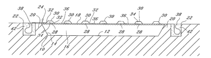
- FIG. 1 is a sectional view through a lagoon or pool of the present invention.
- FIG. 2 is a top plan view of the lagoon or pool shown in FIG. 1 .
- FIG. 3 is a detail sectional view showing the first steps of overlapping the adjacent edges of two panels 26 .
- FIG. 4 is an enlarged view taken along line 4 — 4 of FIG. 3 .
- FIG. 5 is a view similar to FIG. 4 , but showing the formation of the weld at the overlapping edges.
- FIG. 6 is a view similar to FIG. 5 , but showing the formation of a hole in one of the lateral edges of the panels.
- lagoon 10 a lagoon or pool 10 is shown. While lagoon 10 may be formed in dirt, it is also possible to use the blanket of the present invention for covering swimming pools or the like, and therefore the term “pool” as used herein means a swimming pool, a lagoon for containing waste material, or any other type of pool requiring an insulated cover.
- Pool 10 includes a bottom wall 12 having a plurality of side walls 14 .
- the side walls 14 may be vertical or slanted depending upon the particular configuration of the lagoon or pool.
- the bottom wall 12 and the side walls 14 form a pool basin 16 which is adapted to contain a fluid 18 .
- the fluid 18 may be waste material, or it may be the water of a swimming pool, or it could be a fluid within any type of pool requiring an insulated cover.
- the dirt or ground 20 Surrounding the lagoon or pool 10 is dirt or ground 20 .
- the dirt or ground 20 includes a perimeter trench 22 which surrounds the pool 10 .
- a blanket 24 is in covering relation over the upper surface of the fluid 18 within the pool basin 16 .
- Blanket 24 is formed from a plurality of panels 26 which are joined together in the manner described below the joined lateral edges. Each of the panels 26 are shown in detail in FIGS. 3–6 . Each panel 26 includes a lower layer 28 and an upper layer 30 . The upper layer 30 includes welded edges 32 which are welded at the factory and which include an insolative material 34 between the upper and lower layers 28 , 30 . The insulative material is completely enclosed within the double panel formed by lower layer 28 and upper layer 30 .
- the lower layer 28 extends laterally outwardly from the welds 32 to form lateral panel edges 36 which extend around the entire perimeter of the each panel 26 . While the lateral edges 36 are formed by extensions of lower layer 28 , they could also be formed by extensions of upper layer 30 or they could be joined to the lower layer 28 and extend laterally outwardly therefrom.
- the blanket 24 includes a perimeter edge 38 which extends around the outer perimeter of the blanket 24 .
- the perimeter layer 38 is joined to the other panels 26 by means of elongated weld joints 40 , and the edges of the panels 26 are each joined together along elongated welded joints 40 as well.
- the perimeter edge 38 of blanket 24 extends within the perimeter trench 22 and fill dirt 42 is packed around the perimeter edge 38 so as to anchor the blanket at the edges of the pool or lagoon 10 and thereby provide a cover for the fluid 18 within the pool basin 16 .
- the method for forming the weld 40 is shown in FIGS. 3–6 .
- the first step in welding the lateral edges 36 of the panels together is to overlap the lateral edges 36 in the manner shown in FIG. 3 .
- FIG. 4 shows the formation of a heat sealed interface 48 between an upper surface 44 of one panel (on the right in FIG. 4 ) and a lower surface 46 of the other panel (on the left in FIG. 4 ).
- This heat sealed interface 48 is formed by a heat sealing device known as a leister triac unit, model number CH-6060SAMEN, sold by Winkleman Sales Inc., in Buffalo, N.Y. 14220.
- This tool applies heat to the adjoining upper surface of the right hand lateral edge 36 and the lower surface 46 of the left hand lateral layer 36 as shown in FIG. 4 . Heat is applied until the lateral layers 36 are partially melted and then they are joined together by pressing so as to form a heat seal 48 there between.
- the lateral layers 36 are formed of a plastic material which is easily heat sealed. Also shown in FIG. 4 are a plurality of ground or roughed up surfaces 50 adjacent the overlapping layers 36 .
- the roughed up portions 50 are both on the upper surfaces 44 of the two adjoining panels 36 , and are approximately 1 to 2 inches wide.
- FIG. 5 shows the application of a weld material to create the weld joint 40 over the roughed up surfaces 50 .
- a tool for forming the weld joint 40 is an extrusion welding gun, model X2-SC EX, manufactured by Plastic Wekling Technologies International in Diamond Springs, California. This welding gun melts a rope material formed from plastic that deposits the weld 40 over the roughed up surfaces 50 of the panels 36 , thereby securely joining the layers 36 together as shown in FIGS. 5 and 6 .
- FIG. 6 shows the formation of a hole 52 in one of the lateral edges 36 that have been joined together by weld 40 .
- the holes 52 are formed along the sides of each panel 30 in a plurality of places. Holes 52 provide an important function to the blanket 24 . They permit rain water or other water to drain downwardly through the holes 52 from the upper surface of the blanket 24 to the fluid 18 within the lagoon basin 16 . At the same time, these holes 52 permit gasses to escape from the fluid 18 within the lagoon basin 16 upwardly through the holes 52 to escape above the blanket 24 .
- the present invention provides a very strong blanket which can float on the upper surface of the fluid 18 within the lagoon basin 16 while at the same time permitting water to drain through the holes 52 and permitting gasses to escape upwardly through the holes 52 .
- the use of a trench 22 around the perimeter of pool basin 16 also provides an improved means for anchoring the outer perimeter edges of the blanket so as to maintain the blanket in place over the pool.
Landscapes
- Engineering & Computer Science (AREA)
- Architecture (AREA)
- Civil Engineering (AREA)
- Structural Engineering (AREA)
- Sewage (AREA)
Abstract
Description
Claims (23)
Priority Applications (1)
| Application Number | Priority Date | Filing Date | Title |
|---|---|---|---|
| US10/687,008 US6915534B1 (en) | 2003-10-16 | 2003-10-16 | Insulated cover and method for using same |
Applications Claiming Priority (1)
| Application Number | Priority Date | Filing Date | Title |
|---|---|---|---|
| US10/687,008 US6915534B1 (en) | 2003-10-16 | 2003-10-16 | Insulated cover and method for using same |
Publications (1)
| Publication Number | Publication Date |
|---|---|
| US6915534B1 true US6915534B1 (en) | 2005-07-12 |
Family
ID=34710325
Family Applications (1)
| Application Number | Title | Priority Date | Filing Date |
|---|---|---|---|
| US10/687,008 Expired - Lifetime US6915534B1 (en) | 2003-10-16 | 2003-10-16 | Insulated cover and method for using same |
Country Status (1)
| Country | Link |
|---|---|
| US (1) | US6915534B1 (en) |
Cited By (4)
| Publication number | Priority date | Publication date | Assignee | Title |
|---|---|---|---|---|
| US20070245479A1 (en) * | 2006-03-20 | 2007-10-25 | National Spa Cover, Inc. | Spa cover |
| US20070277897A1 (en) * | 2006-06-01 | 2007-12-06 | Kevin Nelson King | Double layer woven fabric |
| CN105971322A (en) * | 2016-06-27 | 2016-09-28 | 宜兴市申益体育设施有限公司 | Insulation cover for heated swimming pool |
| US10920438B2 (en) | 2016-02-08 | 2021-02-16 | Aloi Group Pty Ltd | Pool cover systems and methods |
Citations (10)
| Publication number | Priority date | Publication date | Assignee | Title |
|---|---|---|---|---|
| US3313443A (en) * | 1964-06-26 | 1967-04-11 | Globe Linings Inc | Floating cover for a liquid storage reservoir |
| US3661688A (en) * | 1970-02-18 | 1972-05-09 | Wood Process Oregon Ltd | Composite board laminate |
| US3683428A (en) * | 1970-06-01 | 1972-08-15 | Lester Morris | Rigid, buoyant, insulating and rapid folding swimming pool covers |
| US3927427A (en) * | 1973-06-05 | 1975-12-23 | Harry Eugene Aine | Swimming pool cover |
| US4028750A (en) * | 1974-12-05 | 1977-06-14 | Barracudaverken Aktiebolag | Cover for water-filled outdoor swimming pools |
| JPS62279086A (en) * | 1986-05-29 | 1987-12-03 | Nippon Kokan Kk <Nkk> | Groove profiling method in lap welding |
| US5400549A (en) * | 1993-10-22 | 1995-03-28 | Morgan; William D. | Insulated removable pond cover |
| US5546615A (en) | 1994-11-14 | 1996-08-20 | Waste Management & Design, Inc. | Method and device for providing an insulated cover over a pool |
| US6047415A (en) * | 1998-08-10 | 2000-04-11 | Brown; Ruth A. | Pool cover |
| US6723954B2 (en) * | 2002-01-22 | 2004-04-20 | Hobart Brothers Company | Straight polarity metal cored wire |
-
2003
- 2003-10-16 US US10/687,008 patent/US6915534B1/en not_active Expired - Lifetime
Patent Citations (10)
| Publication number | Priority date | Publication date | Assignee | Title |
|---|---|---|---|---|
| US3313443A (en) * | 1964-06-26 | 1967-04-11 | Globe Linings Inc | Floating cover for a liquid storage reservoir |
| US3661688A (en) * | 1970-02-18 | 1972-05-09 | Wood Process Oregon Ltd | Composite board laminate |
| US3683428A (en) * | 1970-06-01 | 1972-08-15 | Lester Morris | Rigid, buoyant, insulating and rapid folding swimming pool covers |
| US3927427A (en) * | 1973-06-05 | 1975-12-23 | Harry Eugene Aine | Swimming pool cover |
| US4028750A (en) * | 1974-12-05 | 1977-06-14 | Barracudaverken Aktiebolag | Cover for water-filled outdoor swimming pools |
| JPS62279086A (en) * | 1986-05-29 | 1987-12-03 | Nippon Kokan Kk <Nkk> | Groove profiling method in lap welding |
| US5400549A (en) * | 1993-10-22 | 1995-03-28 | Morgan; William D. | Insulated removable pond cover |
| US5546615A (en) | 1994-11-14 | 1996-08-20 | Waste Management & Design, Inc. | Method and device for providing an insulated cover over a pool |
| US6047415A (en) * | 1998-08-10 | 2000-04-11 | Brown; Ruth A. | Pool cover |
| US6723954B2 (en) * | 2002-01-22 | 2004-04-20 | Hobart Brothers Company | Straight polarity metal cored wire |
Cited By (5)
| Publication number | Priority date | Publication date | Assignee | Title |
|---|---|---|---|---|
| US20070245479A1 (en) * | 2006-03-20 | 2007-10-25 | National Spa Cover, Inc. | Spa cover |
| US20070277897A1 (en) * | 2006-06-01 | 2007-12-06 | Kevin Nelson King | Double layer woven fabric |
| US8333220B2 (en) * | 2006-06-01 | 2012-12-18 | Nicolon Corporation | Double layer woven fabric |
| US10920438B2 (en) | 2016-02-08 | 2021-02-16 | Aloi Group Pty Ltd | Pool cover systems and methods |
| CN105971322A (en) * | 2016-06-27 | 2016-09-28 | 宜兴市申益体育设施有限公司 | Insulation cover for heated swimming pool |
Similar Documents
| Publication | Publication Date | Title |
|---|---|---|
| US4603517A (en) | Corner patch support | |
| US1335756A (en) | Roofing | |
| US6915534B1 (en) | Insulated cover and method for using same | |
| US6303204B2 (en) | Earthen liner with clay seam cover | |
| KR101557775B1 (en) | Structures and method for water tank waterproofing concrete of using the panel | |
| WO2001062200A1 (en) | Non-corrosive containment vault | |
| US7111751B2 (en) | Plastic lined concrete tanks equipped with waterstop systems | |
| US5375733A (en) | Corner lock for lining tank bottoms | |
| US5150510A (en) | Method of manufacturing large scale membranes for covering extremely large areas | |
| JPS60123609A (en) | Artificial reservior and construction thereof | |
| JP3816171B2 (en) | Waterproof sheet and construction method | |
| US7762024B1 (en) | Pocket seal for roof | |
| JPH08333737A (en) | Impervious structure of sheet junction part | |
| JPS6229610A (en) | Water-proof construction for soil ground surface | |
| JP2001062420A (en) | Fixing structure for protective mat | |
| JP2003154328A (en) | Construction method for applying impervious sheet to wall surface | |
| US4977662A (en) | Airtight watertight mechanical seam for joining panels of industrial strength fabrics | |
| JP3651499B2 (en) | Method for degassing landfill and stagnant air | |
| JPH02104839A (en) | Waterproofing method of construction | |
| JP2795887B2 (en) | How to shut off the roof | |
| JP2002219434A (en) | Rainwater waterproof sheet and method for treating waste | |
| JP5691110B2 (en) | Rehabilitation method of existing impermeable sheet | |
| JPH09310597A (en) | Waterproof sheet | |
| JPS61232191A (en) | Waterproof execution method of heat accumulating tank | |
| JPH09203028A (en) | Connection method of sheet to be laid out |
Legal Events
| Date | Code | Title | Description |
|---|---|---|---|
| AS | Assignment |
Owner name: CHAMNESS TECHNOLOGY, INC., IOWA Free format text: ASSIGNMENT OF ASSIGNORS INTEREST;ASSIGNOR:JOHANNES, MICHAEL J.;REEL/FRAME:014272/0114 Effective date: 20031013 |
|
| STCF | Information on status: patent grant |
Free format text: PATENTED CASE |
|
| FPAY | Fee payment |
Year of fee payment: 4 |
|
| FPAY | Fee payment |
Year of fee payment: 8 |
|
| FPAY | Fee payment |
Year of fee payment: 12 |
|
| AS | Assignment |
Owner name: AVAILA BANK, IOWA Free format text: CHANGE OF NAME;ASSIGNOR:CARROLL COUNTY STATE BANK;REEL/FRAME:050304/0465 Effective date: 20170117 Owner name: CARROLL COUNTY STATE BANK, IOWA Free format text: SECURITY INTEREST;ASSIGNOR:CHAMNESS BIODEGRADABLES, LLC;REEL/FRAME:050304/0492 Effective date: 20150402 |