US6909802B2 - Image-correspondence position detection device, distance measuring device and apparatus using the same - Google Patents
Image-correspondence position detection device, distance measuring device and apparatus using the same Download PDFInfo
- Publication number
- US6909802B2 US6909802B2 US09/859,103 US85910301A US6909802B2 US 6909802 B2 US6909802 B2 US 6909802B2 US 85910301 A US85910301 A US 85910301A US 6909802 B2 US6909802 B2 US 6909802B2
- Authority
- US
- United States
- Prior art keywords
- correspondence
- correlation
- image
- images
- degree
- Prior art date
- Legal status (The legal status is an assumption and is not a legal conclusion. Google has not performed a legal analysis and makes no representation as to the accuracy of the status listed.)
- Expired - Fee Related, expires
Links
Images
Classifications
-
- G—PHYSICS
- G06—COMPUTING OR CALCULATING; COUNTING
- G06T—IMAGE DATA PROCESSING OR GENERATION, IN GENERAL
- G06T7/00—Image analysis
- G06T7/97—Determining parameters from multiple pictures
Definitions
- the present invention relates to an image-correspondence position detection device and a distance measuring device provided with same.
- the present invention further relates to an image-correspondence position detection device or apparatus provided with a distance measuring device such as, for example, a still camera, movie camera, three-dimensional measuring device and the like.
- non-TTL type passive distance measuring devices for measuring the distance to an object based on the triangulation principle have been realized by combining a pair of optical systems and a pair of image sensors. This principle measures the mutual correspondence position of images formed on a pair of sensors, and converts this position to a distance. In order to measure the correspondence position, the output of a specific plurality of pixels must be sampled from the output of each sensor, and the degree of mutual correspondence of the sampled outputs must be measured.
- the distance measurement data more or less accurately represent the distance of one or another among a plurality of objects, it cannot be known for which part within the distance measurement area the distance is representative.
- an object of the present invention is to provide an image-correspondence position detecting device and distance measuring device provided with same capable of accurately recognizing the boundaries of objects.
- a further object is to provide apparatuses having these devices.
- One aspect of the present invention is an image-correspondence position detecting device comprising an extractor, correlation calculator, correspondence degree calculator, measured correlation value calculator, estimated correlation value calculator, and correspondence degree calculator.
- the extractor samples image data of specific size from a pair of images to obtain a sample image.
- the correlation calculator creates a correlation value row by calculating correlation values representing the degree of correspondence between a pair of sample images while sequentially shifting the sampling position from at least one of the images. Then, the correlation calculator calculates the minimum or maximum positions of correspondence values among the correlation value line, i.e., an integer correspondence position representing a sampling position of optimum degree of correspondence. The correlation calculator interpolates between the correlation values and calculates a minimum value or maximum value, i.e., a decimal correspondence position expressed in units smaller than the magnitude of the pixel of the sampling position having the optimum degree of correspondence.
- the measured correlation value calculator calculates the measured correlation value of a partial correlation value for an optional partial area, which is an area corresponding to each sampling image at the integer correspondence position smaller than the sampling image.
- the estimated correlation value calculator calculates an estimated correlation value of a partial correlation value from the difference between the integer correspondence position and the decimal correspondence position in the partial area based on the assumption that each sampling image is uniformly shifted in each pixel.
- the correspondence degree calculator calculates the degree of correspondence between optional pixels in the partial area from the measured correlation value and the estimated correlation value.
- the degree of correspondence of a partial area is calculated for a sampling image at the integer correspondence position from the measured correlation value and the estimated correlation value of the partial area parts of adequate degree of correspondence and parts of poor degree of correspondence within the sampling image can be discriminated by setting the partial area suitably relative to the sampling image.
- Another aspect of the present invention is the construction of a distance measuring device using the image-correspondence position detecting device described above.
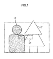
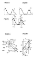
- FIG. 1 illustrates objects at different distances
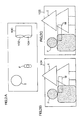
- FIGS. 2A through 2C illustrate objects at different distances
- FIGS. 3A and 3B illustrate image sampling
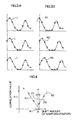
- FIG. 4 illustrates a correlation value line
- FIGS. 5A through 5C illustrate degree of correspondence
- FIGS. 6A and 6B are enlargements of areas ( 1 ) and ( 2 ) in FIG. 5C ;
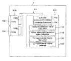
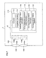
- FIG. 7 is a block diagram of a camera provided with the distance measuring device.
- a distance measuring device 10 is included in a camera 1 , and is provided with a distance measuring section 100 and a calculator 110 .
- the distance measuring section 100 has a pair of sensor units 102 and 104 .
- Each sensor unit 102 and 104 respectively include optical systems 102 a and 104 a , and image sensing elements 102 b and 104 b .
- the optical systems 102 a and 104 a form object image within the distance measurement area.
- the image sensing elements 102 b and 104 b are arranged at the approximate image forming position of the optical systems 102 a and 104 a , and output data relating to the object image to the calculator 110 .
- the image sensing elements 102 b and 104 b are typical line sensors, although area sensor also may be used.
- the distance measuring device 10 is basically a well-known non-TTL type passive distance measuring device, and calculates the distance to an object by the triangulation principle based on the relative shift amount of the object images of the same part of the object on the image sensing elements 102 b and 104 b.
- Parallax occurs because the left sensor unit 104 and a right sensor unit 102 of the distance measuring device 10 have different optical axes to capture the object. For this reason when measuring two objects F and T which are different distances from the distance measuring device 10 , e.g., as shown in the schematic drawing viewed from the front in FIG. 1 and the schematic drawing viewed from the top in FIG. 2A , the positional relationship of the two objects F and T on the sensor surface becomes as shown in FIG. 2B for the left sensor unit 104 and as shown in FIG. 2C for the right sensor unit 102 , such that the positions of the objects F and T appear to be different in the distance measuring area M.
- the calculator 110 comprises a microprocessor, memory and the like, and functions as an extractor 112 , correlation calculator 114 , estimated correlation value calculator 116 , measured correlation value calculator 118 , correspondence degree calculator 120 , and correspondence degree deciding device 122 , as shown in FIG. 7 .
- the extractor 112 extracts rows of data of identical numbers of pixels, i.e., sampling images from data of an object image sensed by the left and right sensor units 104 and 102 .
- the correlation calculator 114 adds the absolute value of the differences between corresponding pixels and calculates the correlation value line f(i) for two extracted data rows. As shown in FIGS.
- the extractor 112 varies the data extraction position of the right sensor unit 102
- the correlation calculator 114 calculates the correlation value f(i) when the data row L of the standard section sensed by the left sensor unit 104 is fixed and the data rows R 1 , R 2 , R 3 of the reference section sensed by the right sensor unit 102 are sequentially shifted, and an integer correspondence position P, a decimal correspondence position Q, and a decimal value d at which the correlation value f(i) is minimum are determined.
- the decimal correspondence position Q is determined by a well-known interpolation method.
- sampling positions are determined which well match the entirety of the sampling images.
- FIGS. 5A and 5B are data rows at the integer correspondence position P having the smallest correlation value F(i), that is, correspondence degree is high, and FIG. 5C is an overlay of these data rows. Due to the influence of parallax between the left and right sensor units 104 and 102 , the degree of correspondence of the left and right images is low in the area ( 2 ) compared to the area ( 1 ) as shown in FIG. 5 C.
- the degree of correspondence can be quantitatively evaluated by calculating an estimated correspondence value using the estimated correspondence value calculator 116 for a small area within the sampling image, calculating the measured correlation value using the measured correlation value calculator 118 , calculating the difference between the estimated correlation value and the measured correlation value using the correlation degree calculator 120 , and comparing this difference to a specific value to determine the degree of correspondence using the correspondence degree determining device 122 .
- FIG. 6A shows an enlargement of area ( 1 ) of FIG. 5 C.
- Points A i ⁇ 1 , and A i are the (i ⁇ 1)-th and i-th data points on the extracted data row L of the standard section, i.e., left sensor unit 104 .
- , i.e., C i
- Points B i ⁇ 1 and B i are the (i ⁇ 1)-th and i-th data points on the extracted data row R of the reference section, i.e., right sensor unit 102 .
- Y i ⁇ 1 ′ is referred to as the estimated correlation value.
- the value Y i can be simply determined from the actual image data. This value Y i is referred to as the measured correlation value.
- the degree of correspondence can be represented by the absolute value of the difference between the measured correlation value Y i and the estimated correlation value Y i ′, that is, the following relationship obtains.
- dY i
- the degree of correspondence can be determined in pixel units by comparing the difference between the measured correspondence value and the estimated correspondence value to a specific value.
- the degree of correspondence calculated as C i
- /2, or C i
- This degree of correspondence may be used to determine the level of correspondence of each pixel, and if this degree of correspondence is added across the entirety of the distance measurement area and the sum is divided by the contrast added across the entirety of the distance measurement area, it becomes the level of correspondence of the entirety of the distance measurement area, i.e., the evaluation value of the reliability of the distance measurement area. In this way even when the contrast is comparatively low, it is possible to detect the level of correspondence of the entire distance measurement area.
- the correspondence degree determining device 122 determines the distance is measurable when the reliability evaluation value is less than a specific value, and determines the distance measurement area is unmeasurable when the reliability evaluation value is greater than a specific value.
- the correspondence degree determining device 122 determines whether or not the measurement data are correct by comparing the degree of correspondence of each pixel to a specific value.
- the distance measuring device 10 is capable of detection each part of an object image even when the true measurement value is different one among the each part by method of comparing the reproduction of the correlation value from the contrast of an object using a determined distance value, and a reproduction of the actual correlation value.
- the present invention is not limited to the previously described embodiments, and may be realized in various other modes.
- the defining equation for quantifying the degree of correspondence may be the opposite of the previously described embodiment describing the relationship of a good/poor degree of correspondence and the magnitude of a numerical value of the degree of correspondence.
- the image-correspondence position detecting device comprises an extractor, correlation calculator, correspondence degree calculator, measured correlation value calculator, estimated correlation value calculator, and correspondence degree calculator.
- the extractor samples image data of specific size from a pair of images to obtain a sample image.
- the correlation calculator creates a correlation value row by calculating correlation values representing the degree of correspondence between a pair of sample images while sequentially shifting the sampling position from at least one of the images. Then, the correlation calculator calculates the minimum or maximum positions of correspondence values among the correlation value row, i.e., an integer correspondence position representing a sampling position of optimum degree of correspondence. The correlation calculator interpolates between the correlation values and calculates a minimum value or maximum value, i.e., a decimal correspondence position expressed in units smaller than the magnitude of a pixel interval of the sampling position having the optimum degree of correspondence.
- the measured correlation value calculator calculates the measured correlation value of a partial correlation value for an optional partial area smaller than the sampling image, that is, an area corresponding to each sampling image at the integer correspondence position.
- the estimated correlation value calculator calculates an estimated correlation value of a partial correlation value from the difference between the integer correspondence position and the decimal correspondence position in the partial area based on the assumption that each sampling image is uniformly shifted in each pixel.
- the correspondence degree calculator calculates the degree of correspondence between optional pixels in the partial area from the measured correlation value and the estimated correlation value.
- the degree of correspondence of a partial area is calculated for a sampling image at the integer correspondence position from the measured correlation value and the estimated correlation value of the partial area. Parts of adequate degree of correspondence and parts of poor degree of correspondence within the sampling image can be discriminated by setting the partial area suitably relative to the sampling image.
- the distance measuring device is provided with a pair of optical systems for forming a pair of object images, and a pair of image sensing elements provided near the image forming position of each optical system.
- the distance measuring device is provided with the previously described image-correspondence position detection device.
- the image-correspondence position detection device obtains sampling images by extracting the image of the distance detection area allocated to each specific area of a pair of images sensed by the pair of image sensing elements, and calculates an integer correspondence position and a decimal correspondence position.
- the distance measuring device discriminates whether the degree of correspondence is good or poor by determining for each pixel the magnitude of a specific value and the degree of correspondence calculated by the image-correspondence position detection device and the distance data calculator which calculates the distance of the distance detection area from the integer correspondence position and the decimal correspondence position. Then, if the value represents a poor degree of correspondence, the pixel is unmeasurable, and if the value represents a good degree of correspondence, the distance measurement data of the distance measurement area are used as the pixel measurement data by the detector.
- a plurality of distance detecting areas are provided, and at least part of the pixels included in the pair of images overlap a plurality of distance detecting areas.
- the distance data is set for optional pixels included in the overlapping plurality of distance detecting areas based on the degree of correspondence determined as “good” among the degrees of correspondence obtained from the plurality of distance detecting areas.
- the distance detecting areas are arranged so as to overlap.
- the distance data of optional pixels arranged so as to overlap can be accurately set based on the degree of correspondence obtained from the plurality of distance detecting areas including the pixel.
- the distance data of the optional pixel are distance data pertaining to a distance measuring area having the best degree of correspondence among the degrees of correspondence obtained from a plurality of distance measuring areas determined to have good degrees of correspondence for that pixel.
- the distance data can be set with the most accuracy by using the distance data having the best degree of correspondence for that pixel.
- the image-correspondence position detection device extracts data of images A′ and B′ while sequentially shifting the sampling position of at least an image B among a pair of images A and B comprising a plurality of pixel rows arranged unidimensionally, and calculates the correlation values of only a specific number of samples to generate a correlation value line f(j). Then, a decimal value d between pixels is determined by interpolating the sampling position of the image having the highest correlation from the generated correlation value line f(j).
- the image-correlation position detection device is provided with an image correlation degree calculator for calculating the degree of correlation dY i of optional pixels in images A′ and B′ by the method described below.
- PA i and PB i are data of the number i optional pixels of A′ and B′ in the combination of A′ and B′ having the smallest correspondence values f(j).
- the degree of correspondence is calculated and quantitatively evaluated for optional pixels of a pair of sampling images by the minimum value of the correlation value line of the sampling images without being limited to the determination of the pair of sampling images having the best correlation.
- the boundary of an object can be accurately recognized in pixel units, for example, by comparing the degree of correspondence to a specific threshold value.
- equation (5)
- equation (5a)
- the image-correspondence position detection device examines the degree of correspondence between optional pixels included in a pair of images comprised of a plurality of pixels.
- the image-correspondence position detection device comprises an extractor, correlation value calculator, measured correlation value calculator, estimated correlation value calculator, degree of correspondence calculator, and reliability evaluation value calculator.
- the extractor samples image data of specific size from a pair of images to obtain a sample image.
- the correlation calculator creates a correlation value line by calculating correlation values representing the degree of correspondence between a pair of sample images while sequentially shifting the sampling position from at least one of the images. Then, the positions of the minimum and maximum correlation values are determined, i.e., the integer correspondence position representing the sampling position having the best degree of correspondence is determined. Finally, interpolation between correlation values is performed, and the sampling positions corresponding to the minimum value and maximum value, i.e., the decimal correspondence positions, are calculated.
- the measured correlation value calculator calculates the measured correlation value of a partial correlation value from pixel data of a partial area smaller than the sampling image and including optional pixels among the sampling image in an area mutually corresponding to sampling images at the integer correspondence position.
- the estimated correlation value calculator calculates an estimated correlation value of a partial correlation value from the difference between the integer correspondence position and the decimal correspondence position in the partial area based on the assumption that each sampling image is uniformly shifted in each pixel.
- the correspondence degree calculator calculates the degree of correspondence between optional pixels in the partial area from the measured correlation value and the estimated correlation value.
- the reliability evaluation value calculator calculates a reliability evaluation value for evaluating the reliability of the sampling image at the integer correspondence position from the previously mentioned degree of correspondence and the change in luminance of the object in the sampling image at the integer correspondence position.
- the degree of correspondence is the even small change in the value according to the degree of contrast when the contrast influences the sampling image.
- the value of the degree of correspondence is corrected by the contrast value, such that the degree of correspondence between sampling images can be objectively evaluated by the reliability evaluation value which is not affected or only slightly affected by the contrast.
- the boundary of the object can be accurately recognized in sampling image units.
- the image-correspondence position detection device extracts images A′ and B′ while sequentially shifting the sampling position of at least an image B among a pair of images A and B comprising a plurality of pixel rows arranged unidimensionally. Then, the correlation values of only a specific number of samples are calculated to generate a correlation value line f(j), and a decimal value d between pixels is determined by interpolating the sampling position of the image having the highest correlation from the generated correlation value line f(j).
- the image-correlation position detection device is provided with an image correlation degree calculator for calculating a reliability evaluation value SY/C for evaluating the degree of correspondence at the correspondence positions of images A′ and B′ by the calculations shown below.
- PA i and PB i are data of optional number i pixels of images A′ and B′ in the combination of A′, B′ having the smallest correlation value f(j).
- an accurate reliability evaluation value unaffected by the contrast of the object can be obtained by adding
- the boundary of the object can be accurately recognized in sampling image units.
- Equation 15a
- C i
- the distance measuring device determines the distance of an object from the correspondence positions of two images formed through two different optical systems.
- the distance measuring device is provided with the previously described image-correspondence position detection device.
- a distance measuring area if provided for measuring distance at least two locations on a screen.
- a reliability evaluation value is calculated for the distance measuring area similar to that of the previously described image-correspondence position detection device.
- the distance measuring device is provided with a selector for selecting one or more distance measurement areas, or determining not select any distance measurement area based on the calculated reliability evaluation value.
- the distance of the distance measurement area can be measured by the triangulation principle from positions in two images of the selected distance measurement areas.
- distance measurement cannot be accomplished for any distance measurement area.
Landscapes
- Engineering & Computer Science (AREA)
- Computer Vision & Pattern Recognition (AREA)
- Physics & Mathematics (AREA)
- General Physics & Mathematics (AREA)
- Theoretical Computer Science (AREA)
- Measurement Of Optical Distance (AREA)
- Automatic Focus Adjustment (AREA)
- Length Measuring Devices By Optical Means (AREA)
Abstract
Description
C i−1/1=Y i−1 /d′ (a)
Y i−1 ′=C i−1 ·d (c)
dY i =|Y i −Y i′| (d)
This equation expresses whether or not d and d′ are equal.
dY j =|Y j −Y j′| (d′)
This equation expresses whether or not d and d″ are equal.
dY i =|Y i −Y i′| (1)
Y i =PA i −PB i (2)
Y i ′=C i×δ (3)
δ=d (where d≦0.5) or 1−d (where d>0.5) (4)
C i =|PA i −PA i+1 (5)
C i =|PA i−1 −PA i+1|/2 (5a)
C i=|(PA i−1 −PA i+1)/2+(PB i−1 −PB 1+1)/2|/2 (5b)
SY/C=Σ|Y i −Y i ′|ΣC i (11)
Y i =PA i −PB i (12)
Y i ′=Ci i×δ (13)
δ=d (where d≦0.5) or 1−d (where d>0.5) (14)
C i =PA i −PA 1+1| (15)
C i =|PA i−1 −PA i+1|/2 (15a)
C i=|(PA i−1 −PA i+1)/2+(PB i−1 −PB i+1)/2|/2 (15b)
Claims (15)
Y i =PA i −PB i (2)
Y i ′=C i×δ (3)
δ=d (where d≦0.5) or 1−d (where d>0.5) (4)
C i =|PA i −PA i+1 (5)
dY i =|Y i −Y i′| (1)
Y i =PA i −PB i (2)
Y i ′=C i×δ (3)
δ=d (where d≦0.5)or 1−d (where d>0.5) (4)
C i =|PA i−1 −PA i+1|/2 (5a)
dY i =|Y i −Y i′| (1)
Y i =PA i −PB i (2)
Y i ′=C i×δ (3)
δ=d (where d≦0.5) or 1−d (where d>0.5) (4)
C i=|(PA i−1 −PA i+1)/2+(PB i−1 −PB i+1)/2|/2 (5b)
SY/C=Σ|Y i −Y i ′|ΣC i (11)
Y i =PA i −PB i (12)
Y i ′=Ci i×δ (13)
δ=d (where d≦0.5) or 1−d (where d<0.5) (14)
C i =|PA i −PA i+1| (15)
SY/C=Σ|Y i −Y i ′|ΣC i (11)
Y i =PA i −PB i (12)
Y i ′=Ci i×δ (13)
δ=d (where d≦0.5) or 1−d (where d>0.5) (14)
C i =|PA i−1 −PA i+1|/2 (15a)
SY/C=Σ|Y i −Y i ′|ΣC i (11)
Y i 32 PA i −PB i (12)
Y i ′=Ci i×δ (13)
δ=d (where d≦0.5) or 1−d (where d>0.5) (14)
C i=|(PA i−1 −PA i+1)/2+(PB i−1 −PB i+1)/2|/2 (15b)
Applications Claiming Priority (2)
| Application Number | Priority Date | Filing Date | Title |
|---|---|---|---|
| JP2000144897A JP2001324305A (en) | 2000-05-17 | 2000-05-17 | Image correspondent position detector and range finder equipped with the same |
| JP2000-144897 | 2000-05-17 |
Publications (2)
| Publication Number | Publication Date |
|---|---|
| US20010055418A1 US20010055418A1 (en) | 2001-12-27 |
| US6909802B2 true US6909802B2 (en) | 2005-06-21 |
Family
ID=18651483
Family Applications (1)
| Application Number | Title | Priority Date | Filing Date |
|---|---|---|---|
| US09/859,103 Expired - Fee Related US6909802B2 (en) | 2000-05-17 | 2001-05-16 | Image-correspondence position detection device, distance measuring device and apparatus using the same |
Country Status (2)
| Country | Link |
|---|---|
| US (1) | US6909802B2 (en) |
| JP (1) | JP2001324305A (en) |
Cited By (11)
| Publication number | Priority date | Publication date | Assignee | Title |
|---|---|---|---|---|
| US20030086013A1 (en) * | 2001-11-02 | 2003-05-08 | Michiharu Aratani | Compound eye image-taking system and apparatus with the same |
| US20040032971A1 (en) * | 2002-07-02 | 2004-02-19 | Honda Giken Kogyo Kabushiki Kaisha | Image analysis device |
| US20040046885A1 (en) * | 2002-09-05 | 2004-03-11 | Eastman Kodak Company | Camera and method for composing multi-perspective images |
| US20060182313A1 (en) * | 2005-02-02 | 2006-08-17 | Visteon Global Technologies, Inc. | System and method for range measurement of a preceding vehicle |
| US20070031008A1 (en) * | 2005-08-02 | 2007-02-08 | Visteon Global Technologies, Inc. | System and method for range measurement of a preceding vehicle |
| US20070127779A1 (en) * | 2005-12-07 | 2007-06-07 | Visteon Global Technologies, Inc. | System and method for range measurement of a preceding vehicle |
| US20090005948A1 (en) * | 2007-06-28 | 2009-01-01 | Faroog Abdel-Kareem Ibrahim | Low speed follow operation and control strategy |
| US20090073257A1 (en) * | 2006-03-14 | 2009-03-19 | Olympus Medical Systems Corp. | Medical image processing apparatus and medical image processing method |
| US20090190827A1 (en) * | 2008-01-25 | 2009-07-30 | Fuji Jukogyo Kabushiki Kaisha | Environment recognition system |
| US20090190800A1 (en) * | 2008-01-25 | 2009-07-30 | Fuji Jukogyo Kabushiki Kaisha | Vehicle environment recognition system |
| US20140278048A1 (en) * | 2009-03-18 | 2014-09-18 | Saab Ab | Calculating time to go and size of an object based on scale correlation between images from an electro optical sensor |
Families Citing this family (19)
| Publication number | Priority date | Publication date | Assignee | Title |
|---|---|---|---|---|
| US8542900B2 (en) | 2007-03-08 | 2013-09-24 | Sync-Rx Ltd. | Automatic reduction of interfering elements from an image stream of a moving organ |
| US9629571B2 (en) | 2007-03-08 | 2017-04-25 | Sync-Rx, Ltd. | Co-use of endoluminal data and extraluminal imaging |
| JP5639764B2 (en) | 2007-03-08 | 2014-12-10 | シンク−アールエックス,リミティド | Imaging and tools for use with moving organs |
| US9375164B2 (en) | 2007-03-08 | 2016-06-28 | Sync-Rx, Ltd. | Co-use of endoluminal data and extraluminal imaging |
| US11064964B2 (en) | 2007-03-08 | 2021-07-20 | Sync-Rx, Ltd | Determining a characteristic of a lumen by measuring velocity of a contrast agent |
| US10716528B2 (en) | 2007-03-08 | 2020-07-21 | Sync-Rx, Ltd. | Automatic display of previously-acquired endoluminal images |
| US11197651B2 (en) | 2007-03-08 | 2021-12-14 | Sync-Rx, Ltd. | Identification and presentation of device-to-vessel relative motion |
| JP5231119B2 (en) * | 2008-07-31 | 2013-07-10 | オリンパス株式会社 | Display device |
| US9974509B2 (en) * | 2008-11-18 | 2018-05-22 | Sync-Rx Ltd. | Image super enhancement |
| US9095313B2 (en) | 2008-11-18 | 2015-08-04 | Sync-Rx, Ltd. | Accounting for non-uniform longitudinal motion during movement of an endoluminal imaging probe |
| US11064903B2 (en) | 2008-11-18 | 2021-07-20 | Sync-Rx, Ltd | Apparatus and methods for mapping a sequence of images to a roadmap image |
| US9101286B2 (en) | 2008-11-18 | 2015-08-11 | Sync-Rx, Ltd. | Apparatus and methods for determining a dimension of a portion of a stack of endoluminal data points |
| US9144394B2 (en) | 2008-11-18 | 2015-09-29 | Sync-Rx, Ltd. | Apparatus and methods for determining a plurality of local calibration factors for an image |
| US10362962B2 (en) | 2008-11-18 | 2019-07-30 | Synx-Rx, Ltd. | Accounting for skipped imaging locations during movement of an endoluminal imaging probe |
| EP2723231A4 (en) | 2011-06-23 | 2015-02-25 | Sync Rx Ltd | CLEANING LUMINAL BACKGROUND |
| JP5890816B2 (en) * | 2013-09-30 | 2016-03-22 | 富士重工業株式会社 | Filtering device and environment recognition system |
| JP6916419B2 (en) * | 2013-11-26 | 2021-08-11 | 株式会社ニコン | Focus adjuster |
| US9609200B2 (en) * | 2014-09-24 | 2017-03-28 | Panavision International, L.P. | Distance measurement device for motion picture camera focus applications |
| CN113252700B (en) * | 2021-07-01 | 2021-09-21 | 湖南大学 | Method, equipment and system for detecting structural cracks |
Citations (4)
| Publication number | Priority date | Publication date | Assignee | Title |
|---|---|---|---|---|
| JPH1026526A (en) | 1996-07-10 | 1998-01-27 | Fuji Photo Film Co Ltd | Triangulation type range finding method |
| US5768404A (en) * | 1994-04-13 | 1998-06-16 | Matsushita Electric Industrial Co., Ltd. | Motion and disparity estimation method, image synthesis method, and apparatus for implementing same methods |
| US5867591A (en) * | 1995-04-21 | 1999-02-02 | Matsushita Electric Industrial Co., Ltd. | Method of matching stereo images and method of measuring disparity between these image |
| US6021209A (en) * | 1996-08-06 | 2000-02-01 | Fuji Electric Co., Ltd. | Distance detection method using images |
-
2000
- 2000-05-17 JP JP2000144897A patent/JP2001324305A/en active Pending
-
2001
- 2001-05-16 US US09/859,103 patent/US6909802B2/en not_active Expired - Fee Related
Patent Citations (4)
| Publication number | Priority date | Publication date | Assignee | Title |
|---|---|---|---|---|
| US5768404A (en) * | 1994-04-13 | 1998-06-16 | Matsushita Electric Industrial Co., Ltd. | Motion and disparity estimation method, image synthesis method, and apparatus for implementing same methods |
| US5867591A (en) * | 1995-04-21 | 1999-02-02 | Matsushita Electric Industrial Co., Ltd. | Method of matching stereo images and method of measuring disparity between these image |
| JPH1026526A (en) | 1996-07-10 | 1998-01-27 | Fuji Photo Film Co Ltd | Triangulation type range finding method |
| US6021209A (en) * | 1996-08-06 | 2000-02-01 | Fuji Electric Co., Ltd. | Distance detection method using images |
Cited By (19)
| Publication number | Priority date | Publication date | Assignee | Title |
|---|---|---|---|---|
| US20030086013A1 (en) * | 2001-11-02 | 2003-05-08 | Michiharu Aratani | Compound eye image-taking system and apparatus with the same |
| US20040032971A1 (en) * | 2002-07-02 | 2004-02-19 | Honda Giken Kogyo Kabushiki Kaisha | Image analysis device |
| US7221777B2 (en) * | 2002-07-02 | 2007-05-22 | Honda Giken Kogyo Kabushiki Kaisha | Image analysis device |
| US20040046885A1 (en) * | 2002-09-05 | 2004-03-11 | Eastman Kodak Company | Camera and method for composing multi-perspective images |
| US7466336B2 (en) * | 2002-09-05 | 2008-12-16 | Eastman Kodak Company | Camera and method for composing multi-perspective images |
| US20060182313A1 (en) * | 2005-02-02 | 2006-08-17 | Visteon Global Technologies, Inc. | System and method for range measurement of a preceding vehicle |
| US7561721B2 (en) | 2005-02-02 | 2009-07-14 | Visteon Global Technologies, Inc. | System and method for range measurement of a preceding vehicle |
| US20070031008A1 (en) * | 2005-08-02 | 2007-02-08 | Visteon Global Technologies, Inc. | System and method for range measurement of a preceding vehicle |
| US7623681B2 (en) | 2005-12-07 | 2009-11-24 | Visteon Global Technologies, Inc. | System and method for range measurement of a preceding vehicle |
| US20070127779A1 (en) * | 2005-12-07 | 2007-06-07 | Visteon Global Technologies, Inc. | System and method for range measurement of a preceding vehicle |
| US20090073257A1 (en) * | 2006-03-14 | 2009-03-19 | Olympus Medical Systems Corp. | Medical image processing apparatus and medical image processing method |
| US8184146B2 (en) * | 2006-03-14 | 2012-05-22 | Olympus Medical Systems Corp. | Medical image processing apparatus and medical image processing method |
| US20090005948A1 (en) * | 2007-06-28 | 2009-01-01 | Faroog Abdel-Kareem Ibrahim | Low speed follow operation and control strategy |
| US20090190800A1 (en) * | 2008-01-25 | 2009-07-30 | Fuji Jukogyo Kabushiki Kaisha | Vehicle environment recognition system |
| US20090190827A1 (en) * | 2008-01-25 | 2009-07-30 | Fuji Jukogyo Kabushiki Kaisha | Environment recognition system |
| US8244027B2 (en) * | 2008-01-25 | 2012-08-14 | Fuji Jukogyo Kabushiki Kaisha | Vehicle environment recognition system |
| US8437536B2 (en) | 2008-01-25 | 2013-05-07 | Fuji Jukogyo Kabushiki Kaisha | Environment recognition system |
| US20140278048A1 (en) * | 2009-03-18 | 2014-09-18 | Saab Ab | Calculating time to go and size of an object based on scale correlation between images from an electro optical sensor |
| US9208690B2 (en) * | 2009-03-18 | 2015-12-08 | Saab Ab | Calculating time to go and size of an object based on scale correlation between images from an electro optical sensor |
Also Published As
| Publication number | Publication date |
|---|---|
| JP2001324305A (en) | 2001-11-22 |
| US20010055418A1 (en) | 2001-12-27 |
Similar Documents
| Publication | Publication Date | Title |
|---|---|---|
| US6909802B2 (en) | Image-correspondence position detection device, distance measuring device and apparatus using the same | |
| US7697749B2 (en) | Stereo image processing device | |
| US5825915A (en) | Object detecting apparatus in which the position of a planar object is estimated by using hough transform | |
| CN102737370B (en) | Method and device for detecting image foreground | |
| US8111877B2 (en) | Image processing device and storage medium storing image processing program | |
| US7769227B2 (en) | Object detector | |
| JP2006513502A (en) | How to get a complete depth map | |
| GB2319684A (en) | Scene change detection | |
| US20090207260A1 (en) | Image pickup apparatus and image pickup method | |
| JP2006090896A (en) | Stereo image processing device | |
| US6519358B1 (en) | Parallax calculating apparatus, distance calculating apparatus, methods of the same, and information providing media | |
| JP3452794B2 (en) | Visibility measurement device | |
| Schramm et al. | Data fusion for 3D thermal imaging using depth and stereo camera for robust self-localization | |
| CN102075684A (en) | Imaging apparatus and image processing method | |
| CN106934792B (en) | 3D effect detection method, device and system of display module | |
| JP2004109009A (en) | Target angular velocity measuring device and target angular velocity measuring method | |
| EP2105882A1 (en) | Image processing apparatus, image processing method, and program | |
| US20020085747A1 (en) | Image processing apparatus and method, image capturing apparatus, and information provision medium | |
| KR20220065435A (en) | Image Registration Technique of Hyperspectral Image using Optical Flow Algorithm | |
| JP2000331169A (en) | Image motion vector measurement method and apparatus | |
| JPH1096607A (en) | Object detection device and plane estimation method | |
| JP3432937B2 (en) | Moving object detecting device and moving object detecting method | |
| JP2007114168A (en) | Image processing method, device, and program | |
| JPH11223516A (en) | Three dimensional image pickup device | |
| CN121437588B (en) | Occlusion detection method, system, and storage medium based on image registration and depth map |
Legal Events
| Date | Code | Title | Description |
|---|---|---|---|
| AS | Assignment |
Owner name: MINOLTA CO., LTD., JAPAN Free format text: ASSIGNMENT OF ASSIGNORS INTEREST;ASSIGNOR:NAKAMURA, KENJI;REEL/FRAME:012026/0644 Effective date: 20010528 |
|
| FEPP | Fee payment procedure |
Free format text: PAYOR NUMBER ASSIGNED (ORIGINAL EVENT CODE: ASPN); ENTITY STATUS OF PATENT OWNER: LARGE ENTITY |
|
| CC | Certificate of correction | ||
| FEPP | Fee payment procedure |
Free format text: PAYER NUMBER DE-ASSIGNED (ORIGINAL EVENT CODE: RMPN); ENTITY STATUS OF PATENT OWNER: LARGE ENTITY |
|
| FEPP | Fee payment procedure |
Free format text: PAYOR NUMBER ASSIGNED (ORIGINAL EVENT CODE: ASPN); ENTITY STATUS OF PATENT OWNER: LARGE ENTITY |
|
| FPAY | Fee payment |
Year of fee payment: 4 |
|
| FPAY | Fee payment |
Year of fee payment: 8 |
|
| REMI | Maintenance fee reminder mailed | ||
| LAPS | Lapse for failure to pay maintenance fees | ||
| STCH | Information on status: patent discontinuation |
Free format text: PATENT EXPIRED DUE TO NONPAYMENT OF MAINTENANCE FEES UNDER 37 CFR 1.362 |
|
| FP | Lapsed due to failure to pay maintenance fee |
Effective date: 20170621 |