US6877962B2 - Dishwasher pump mounting assembly - Google Patents
Dishwasher pump mounting assembly Download PDFInfo
- Publication number
- US6877962B2 US6877962B2 US10/375,843 US37584303A US6877962B2 US 6877962 B2 US6877962 B2 US 6877962B2 US 37584303 A US37584303 A US 37584303A US 6877962 B2 US6877962 B2 US 6877962B2
- Authority
- US
- United States
- Prior art keywords
- mounting plate
- plunger
- lever
- assembly
- pump mounting
- Prior art date
- Legal status (The legal status is an assumption and is not a legal conclusion. Google has not performed a legal analysis and makes no representation as to the accuracy of the status listed.)
- Expired - Fee Related, expires
Links
Images


Classifications
-
- F—MECHANICAL ENGINEERING; LIGHTING; HEATING; WEAPONS; BLASTING
- F04—POSITIVE - DISPLACEMENT MACHINES FOR LIQUIDS; PUMPS FOR LIQUIDS OR ELASTIC FLUIDS
- F04D—NON-POSITIVE-DISPLACEMENT PUMPS
- F04D29/00—Details, component parts, or accessories
- F04D29/60—Mounting; Assembling; Disassembling
- F04D29/605—Mounting; Assembling; Disassembling specially adapted for liquid pumps
-
- A—HUMAN NECESSITIES
- A47—FURNITURE; DOMESTIC ARTICLES OR APPLIANCES; COFFEE MILLS; SPICE MILLS; SUCTION CLEANERS IN GENERAL
- A47L—DOMESTIC WASHING OR CLEANING; SUCTION CLEANERS IN GENERAL
- A47L15/00—Washing or rinsing machines for crockery or tableware
- A47L15/42—Details
- A47L15/4214—Water supply, recirculation or discharge arrangements; Devices therefor
- A47L15/4225—Arrangements or adaption of recirculation or discharge pumps
-
- A—HUMAN NECESSITIES
- A47—FURNITURE; DOMESTIC ARTICLES OR APPLIANCES; COFFEE MILLS; SPICE MILLS; SUCTION CLEANERS IN GENERAL
- A47L—DOMESTIC WASHING OR CLEANING; SUCTION CLEANERS IN GENERAL
- A47L15/00—Washing or rinsing machines for crockery or tableware
- A47L15/42—Details
- A47L15/4246—Details of the tub
-
- Y—GENERAL TAGGING OF NEW TECHNOLOGICAL DEVELOPMENTS; GENERAL TAGGING OF CROSS-SECTIONAL TECHNOLOGIES SPANNING OVER SEVERAL SECTIONS OF THE IPC; TECHNICAL SUBJECTS COVERED BY FORMER USPC CROSS-REFERENCE ART COLLECTIONS [XRACs] AND DIGESTS
- Y10—TECHNICAL SUBJECTS COVERED BY FORMER USPC
- Y10T—TECHNICAL SUBJECTS COVERED BY FORMER US CLASSIFICATION
- Y10T292/00—Closure fasteners
- Y10T292/08—Bolts
- Y10T292/096—Sliding
- Y10T292/1014—Operating means
Definitions
- Dishwashing machines include a tub with a bottom wall in which a pump is mounted for supplying wash and rinse water to the spray arms of the dishwasher.
- the pump is typically secured to a mounting plate which is then mounted within the bottom wall of the tub, with a sealing gasket between the pump mounting plate and the tub bottom wall.
- Conventional mounting means for mounting the pump mounting plate to the tub have several problems.
- the mounting mechanisms are attached and detached during the installation or repair processes.
- Such loose fasteners or connectors can end up being lost or misplaced.
- fasteners such as screws which extend through both the housing and the bottom wall of the tub transmit the noise vibrations from the pump to the tub, which then acts as an amplifier for undesirable noise.
- conventional connectors for securing the pump housing to the tub require tools for installation and removal.
- a primary objective of the present invention is the provision of an improved dishwasher pump mounting assembly.
- Another objective of the present invention is the provision of a dishwasher pump mounting assembly which is mounted on the pump mounting plate and remains in place when in both the locked and unlocked position.
- a further objective of the present invention is the provision of a dishwasher mounting assembly which requires no tools.
- Still another objective of the present invention is the provision of a dishwasher pump mounting assembly which is quick and easy to move between locked and unlocked positions.
- Another objective of the present invention is the provision of an improved method of mounting a pump to the tub of a dishwasher.
- Yet another objective of the present invention is the provision of a dishwasher pump mounting assembly which is economical to manufacture, and durable and efficient in use.
- the dishwasher pump mounting assembly of the present invention includes a pump mounting plate which extends through a hole in the bottom wall of the dishwasher tub and is supported by the annular edge of the hole.
- the pump of the dishwasher is mounted in the pump mounting plate.
- the pump mounting plate is releasably secured to the bottom wall of the tub using a plurality of lever-type locking members.
- Each locking member includes a lever pivotal between an unlocked position disengaged from the tub bottom wall and a locked position engaging the tub bottom wall.
- a slideable plunger extends into each lever and is movable between an extended position to retain the lever in the locked position, and a retracted position permitting the lever to be moved to the unlocked position.
- the plunger includes resilient tabs which snap fit into the lever so that the plunger is not completely removable from the lever.
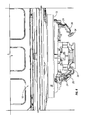
- FIG. 1 is a perspective view looking upwardly at the bottom wall of the dishwasher tub and showing the pump mounting assembly of the present invention in an unlocked condition.
- FIG. 1A is a fragmentary section view taken generally along lines 1 A— 1 A of FIG. 1 .
- FIG. 2 is similar to FIG. 1 , but shows the pump mounting assembly of the present invention in a locked condition.
- FIG. 3 is an enlarged perspective view of one of the locking members shown in the unlocked condition of FIG. 1 .
- FIG. 4 is an enlarged perspective view one of the locking members shown in the locked condition of FIG. 2 .
- FIG. 5 is a side elevation view showing the pump mounting assembly of the present invention in a locked condition.
- FIG. 6 is a side elevation view showing the pump mounting assembly in an unlocked condition.
- FIG. 7 is a perspective view of the lock lever of the pump mounting assembly.
- FIG. 8 is a perspective view of the plunger of the pump mounting assembly.
- a conventional dishwasher tub 10 includes a bottom wall 12 having a downwardly formed annulus 18 including annular flange 13 defining a hole or opening 14 therein.
- a pump mounting plate 16 extends through the hole 14 and includes a perimeter flange 17 , as shown in FIG. 1A , with a diameter greater than the diameter of the hole 14 , such that the flange 17 is supported within the annulus 18 of the bottom wall 12 by the annular flange 13 surrounding the hole 14 .
- a gasket 19 resides within the annulus 18 between the pump mounting plate flange 17 and the annular flange 13 to provide sealing engagement.
- the pump mounting plate 16 includes a plurality of pairs of ears 20 , 21 extending downwardly from the mounting plate 16 .
- a cylindrical boss 22 extends radially outwardly between each pair of ears 20 and 21 , as best seen in FIG. 3 .
- each locking member 24 includes a lever 26 having a pair stub shafts 28 ( FIG. 7 ) which define a pivot axis 29 for the lever 26 .
- One stub shaft 28 is received within a hole 30 in the ear 20 , while the other stub shaft 28 is snap fit or press fit into a recess 32 in the other ear 21 .
- the lever 26 is thus pivotal about the substantially horizontal axis 29 , with the pivotal movement being between the unlocked position as shown in FIGS. 1 and 3 , and the locked position shown in FIGS. 2 and 4 .
- a slideable plunger 34 ( FIG. 8 ) is mounted in each lever 26 and is movable between a retracted and extended position. When the plunger 34 is in the retracted position, the lever 26 is movable to and from the unlocked position (FIGS. 1 and 3 ).
- the plunger 34 has a terminal end 36 which is received in the cylindrical boss 22 of the pump mounting plate 16 when the plunger 34 is in the extended position, so as to retain the lever 26 in the locked position.
- the plunger 34 includes an enlarged head 38 for easy grasping for movement of the plunger 34 between the extended and retracted positions.
- the plunger 34 also includes resilient tabs 40 which are adapted to snap fit past resilient arms 42 in the lever 26 so that the plunger 34 is retained in the lever 26 , whether in the extended or retracted positions. Thus, the plunger 34 cannot be accidentally disconnected from the lever 26 . Also, the lever 26 is not disconnected from the pump mounting plate 16 when moving between the unlocked and locked positions.
- the plunger 34 further has an ear 39 located between tabs 40 and enlarged head 38 . The ear 39 engages a detent 41 to frictionally hold the plunger 34 in the extended or locked position. Accordingly, there are no loose or disconnected pieces which may become lost or misplaced when the pump mounting plate 16 is installed or removed for repair work.
- the gasket 19 is positioned within the annulus 18 around the hole 14 of the bottom wall 12 .
- the pump mounting plate 16 is then set downwardly through the hole 14 such that the perimeter flange 17 engages the gasket 19 and is supported by Flange 13 of the annulus 18 .
- the levers 26 of the locking members 24 are in the unlocked position and the plungers 34 of the locking members 24 are in the retracted positions, as shown in FIGS. 1 and 3 .
- the levers 26 can be rotated upwardly to a substantially horizontal position engaging the flange 13 of the annulus 18 of the bottom wall 12 of the tub 10 .
- the plunger 34 is then inserted or extended into the lever 26 so that the end 36 resides within the cylindrical boss 22 , which prevents the lever 26 from moving out of the locked position to the unlocked position.
- the heads 38 of the plungers 34 can be easily grasped to pull the plungers 34 from the extended position to the retracted position releasing protection 39 from detent 41 , thereby allowing the levers 26 to be pivoted downwardly from the locked position to the unlocked position.
- the pump mounting plate 16 and associated pump can then be pulled out of the tub 10 for work.
Abstract
A dishwasher pump mounting assembly is provided, and includes a pump mounting plate which is supported by the bottom wall of the dishwasher tub and extends through a hole in the bottom wall. A plurality of locking members secure the pump mounting plate to the bottom wall and prevent upward movement of the housing. Each lock member includes a pivotal lever moveable between locked and unlocked position, and a slideable plunger movable between extended and retracted positions within the lever. In the extended position, the plunger maintains the lever in the locked position. In the retracted position, the lever is free to be pivoted between the unlocked and locked positions.
Description
Dishwashing machines include a tub with a bottom wall in which a pump is mounted for supplying wash and rinse water to the spray arms of the dishwasher. The pump is typically secured to a mounting plate which is then mounted within the bottom wall of the tub, with a sealing gasket between the pump mounting plate and the tub bottom wall.
Conventional mounting means for mounting the pump mounting plate to the tub have several problems. First, the mounting mechanisms are attached and detached during the installation or repair processes. Such loose fasteners or connectors can end up being lost or misplaced. Secondly, fasteners such as screws which extend through both the housing and the bottom wall of the tub transmit the noise vibrations from the pump to the tub, which then acts as an amplifier for undesirable noise. Furthermore, conventional connectors for securing the pump housing to the tub require tools for installation and removal.
Therefore, a primary objective of the present invention is the provision of an improved dishwasher pump mounting assembly.
Another objective of the present invention is the provision of a dishwasher pump mounting assembly which is mounted on the pump mounting plate and remains in place when in both the locked and unlocked position.
A further objective of the present invention is the provision of a dishwasher mounting assembly which requires no tools.
Still another objective of the present invention is the provision of a dishwasher pump mounting assembly which is quick and easy to move between locked and unlocked positions.
Another objective of the present invention is the provision of an improved method of mounting a pump to the tub of a dishwasher.
Yet another objective of the present invention is the provision of a dishwasher pump mounting assembly which is economical to manufacture, and durable and efficient in use.
These and other objectives will become apparent from the following description of the invention.
The dishwasher pump mounting assembly of the present invention includes a pump mounting plate which extends through a hole in the bottom wall of the dishwasher tub and is supported by the annular edge of the hole. The pump of the dishwasher is mounted in the pump mounting plate. The pump mounting plate is releasably secured to the bottom wall of the tub using a plurality of lever-type locking members. Each locking member includes a lever pivotal between an unlocked position disengaged from the tub bottom wall and a locked position engaging the tub bottom wall. A slideable plunger extends into each lever and is movable between an extended position to retain the lever in the locked position, and a retracted position permitting the lever to be moved to the unlocked position. The plunger includes resilient tabs which snap fit into the lever so that the plunger is not completely removable from the lever. Thus, the levers and plungers are connected to the pump mounting plate in both the locked and unlocked positions to avoid losing any parts or pieces when the pump mounting plate is installed or removed for repair work.
A conventional dishwasher tub 10 includes a bottom wall 12 having a downwardly formed annulus 18 including annular flange 13 defining a hole or opening 14 therein. A pump mounting plate 16 extends through the hole 14 and includes a perimeter flange 17, as shown in FIG. 1A , with a diameter greater than the diameter of the hole 14, such that the flange 17 is supported within the annulus 18 of the bottom wall 12 by the annular flange 13 surrounding the hole 14. A gasket 19 resides within the annulus 18 between the pump mounting plate flange 17 and the annular flange 13 to provide sealing engagement.
The pump mounting plate 16 includes a plurality of pairs of ears 20, 21 extending downwardly from the mounting plate 16. A cylindrical boss 22 extends radially outwardly between each pair of ears 20 and 21, as best seen in FIG. 3.
The pump mounting assembly of the present invention includes locking members 24 which are movable between an unlocked position disengaged from the flange 13 of bottom wall 12 (FIG. 1 ) and a locked position engaging the flange 13 of bottom wall 12 (FIG. 2 ) so as to prevent upward movement of the pump mounting plate 16 relative to the bottom wall 12. More particularly, each locking member 24 includes a lever 26 having a pair stub shafts 28 (FIG. 7 ) which define a pivot axis 29 for the lever 26. One stub shaft 28 is received within a hole 30 in the ear 20, while the other stub shaft 28 is snap fit or press fit into a recess 32 in the other ear 21. The lever 26 is thus pivotal about the substantially horizontal axis 29, with the pivotal movement being between the unlocked position as shown in FIGS. 1 and 3 , and the locked position shown in FIGS. 2 and 4 .
A slideable plunger 34 (FIG. 8 ) is mounted in each lever 26 and is movable between a retracted and extended position. When the plunger 34 is in the retracted position, the lever 26 is movable to and from the unlocked position (FIGS. 1 and 3). The plunger 34 has a terminal end 36 which is received in the cylindrical boss 22 of the pump mounting plate 16 when the plunger 34 is in the extended position, so as to retain the lever 26 in the locked position. The plunger 34 includes an enlarged head 38 for easy grasping for movement of the plunger 34 between the extended and retracted positions.
The plunger 34 also includes resilient tabs 40 which are adapted to snap fit past resilient arms 42 in the lever 26 so that the plunger 34 is retained in the lever 26, whether in the extended or retracted positions. Thus, the plunger 34 cannot be accidentally disconnected from the lever 26. Also, the lever 26 is not disconnected from the pump mounting plate 16 when moving between the unlocked and locked positions. The plunger 34 further has an ear 39 located between tabs 40 and enlarged head 38. The ear 39 engages a detent 41 to frictionally hold the plunger 34 in the extended or locked position. Accordingly, there are no loose or disconnected pieces which may become lost or misplaced when the pump mounting plate 16 is installed or removed for repair work.
In the initial installation of the pump mounting plate 16 into the tub 10, the gasket 19 is positioned within the annulus 18 around the hole 14 of the bottom wall 12. The pump mounting plate 16 is then set downwardly through the hole 14 such that the perimeter flange 17 engages the gasket 19 and is supported by Flange 13 of the annulus 18. During this setting step, the levers 26 of the locking members 24 are in the unlocked position and the plungers 34 of the locking members 24 are in the retracted positions, as shown in FIGS. 1 and 3 . After the pump mounting plate 16 is set, the levers 26 can be rotated upwardly to a substantially horizontal position engaging the flange 13 of the annulus 18 of the bottom wall 12 of the tub 10. The plunger 34 is then inserted or extended into the lever 26 so that the end 36 resides within the cylindrical boss 22, which prevents the lever 26 from moving out of the locked position to the unlocked position.
If repair work needs to be done on the pump, the heads 38 of the plungers 34 can be easily grasped to pull the plungers 34 from the extended position to the retracted position releasing protection 39 from detent 41, thereby allowing the levers 26 to be pivoted downwardly from the locked position to the unlocked position. The pump mounting plate 16 and associated pump can then be pulled out of the tub 10 for work.
From the foregoing, it can be seen that the present invention accomplishes at least all of the stated objectives.
The invention has been shown and described above with the preferred embodiments, and it is understood that many modifications, substitutions, and additions may be made which are within the intended spirit and scope of the invention. From the foregoing, it can be seen that the present invention accomplishes at least all of its stated objectives.
Claims (22)
1. In combination with a dishwasher having a tub including a bottom annulus, an assembly for mounting a pump to the tub, comprising:
a pump mounting plate resting within the bottom annulus and supporting the pump;
a plurality of locking members on the pump mounting plate and movable between an unlocked position disengaged from the tub and a locked position engaged with the tub for locking the pump mounting plate to the tub; and
each locking member including a lever mounted on the mounting plate and a plunger slideably associated with the lever.
2. The assembly of claim 1 wherein the locking members are connected to the pump mounting plate in both the locked and unlocked positions.
3. The assembly of claim 1 further comprising a gasket between the pump mounting plate and the annulus.
4. The assembly of claim 1 wherein the plunger includes at least one resilient tab to preclude complete removal of the plunger from the lever.
5. The assembly of claim 4 wherein the lever includes an arm into which the tab of the plunger retentively snap fits.
6. The assembly of claim 1 wherein one of the plunger and the lever includes a projection and other of the plunger and the lever includes a detent with the projection being cooperably engageable with the detent for maintaining the plunger in the locked position.
7. The assembly of claim 1 wherein the plunger remains mounted in the lever in both extended and retracted positions.
8. The assembly of claim 1 wherein the pump mounting plate includes a boss for receiving the plunger in an extended position.
9. The assembly of claim 1 wherein the pump mounting plate includes a pair of spaced apart ears for each locking member, with each locking member having an axle for pivotal mounting to the ears.
10. The assembly of claim 1 wherein the locking members are in substantially vertical orientations in the unlocked positions and substantially horizontal orientations in the locked positions.
11. The assembly of claim 1 wherein the locking members pivot about a substantially horizontal axis.
12. A method of assembling a pump mounting plate including a pump to a dishwasher tub bottom, comprising:
setting the pump mounting plate downwardly through a hole in the tub bottom:
supporting the pump mounting plate with an annular flange extending around the hole;
moving a locking lever on the pump mounting plate from an unlocked position to a locked position to secure the pump mounting plate against upwardly movement relative to the tub bottom; and
moving a plunger through the locking lever and between extended and retracted positions to retain and release the locking lever with respect to the locked and unlocked positions.
13. The method of claim 12 further comprising mounting the locking lever on the pump mounting plate for retention in both the locked and unlocked positions.
14. The method of claim 12 further comprising snap fitting the plunger to the lever for retention therein in both the extended and retracted positions.
15. The method of claim 12 further comprising installing a gasket between the tub and the pump mounting plate.
16. The method of claim 12 wherein the lever pivots between a substantially vertical orientation in the locked position and a substantially horizontal orientation in the locked position.
17. An assembly for mounting a pump in a dishwasher, the dishwasher having a tub with a hole in a bottom wall thereof, the assembly comprising:
a pump mounting plate adapted to extend through the hole in the tub and be supported by the tub and adapted to support the pump;
a plurality of lock levers movable between an unlocked position disengaged from the bottom wall and a locked position engaging the bottom wall; and
a plunger associated with each lock lever and being slidable between an extended position to retain the lock lever in the locked position and a retracted position to allow the lock lever to move to the unlocked position.
18. The assembly of claim 17 further comprising a boss on the pump mounting plate to receive the plunger in the extended position.
19. The assembly of claim 17 wherein each plunger has a resilient tab to snap fit into the lock lever and preclude complete removal of the plunger from the lock lever.
20. The assembly of claim 17 wherein the lock lever is secured to the pump mounting plate in both the locked and unlocked positions.
21. The assembly of claim 17 wherein the pump mounting plate includes a pair of spaced apart ears and each lock lever includes an axle for pivotal mounting between of the pairs of ears.
22. The assembly of claim 17 wherein one of the lock lever and the plunger includes a projection and the other of the lock lever and the plunger includes a detent with the projection being cooperably engageable with the detent for maintaining the plunger in the extended, locked position.
Priority Applications (2)
| Application Number | Priority Date | Filing Date | Title |
|---|---|---|---|
| US10/375,843 US6877962B2 (en) | 2003-02-25 | 2003-02-25 | Dishwasher pump mounting assembly |
| CA 2456439 CA2456439C (en) | 2003-02-25 | 2004-02-03 | Dishwasher pump mounting assembly |
Applications Claiming Priority (1)
| Application Number | Priority Date | Filing Date | Title |
|---|---|---|---|
| US10/375,843 US6877962B2 (en) | 2003-02-25 | 2003-02-25 | Dishwasher pump mounting assembly |
Publications (2)
| Publication Number | Publication Date |
|---|---|
| US20040166001A1 US20040166001A1 (en) | 2004-08-26 |
| US6877962B2 true US6877962B2 (en) | 2005-04-12 |
Family
ID=32869053
Family Applications (1)
| Application Number | Title | Priority Date | Filing Date |
|---|---|---|---|
| US10/375,843 Expired - Fee Related US6877962B2 (en) | 2003-02-25 | 2003-02-25 | Dishwasher pump mounting assembly |
Country Status (2)
| Country | Link |
|---|---|
| US (1) | US6877962B2 (en) |
| CA (1) | CA2456439C (en) |
Cited By (6)
| Publication number | Priority date | Publication date | Assignee | Title |
|---|---|---|---|---|
| US20060086380A1 (en) * | 2004-10-21 | 2006-04-27 | Lg Electronics Inc. | Dishwasher |
| US20070251555A1 (en) * | 2004-09-16 | 2007-11-01 | Lg Electronics, Inc. | Dishwasher |
| US20070272284A1 (en) * | 2006-05-25 | 2007-11-29 | Lg Electronics Inc. | Dishwasher |
| US10113654B2 (en) * | 2015-01-27 | 2018-10-30 | Haier Us Appliance Solutions, Inc. | Water diverter assembly for a dishwashing appliance |
| US11033170B2 (en) | 2019-05-03 | 2021-06-15 | Haier Us Appliance Solutions, Inc. | Sump mounting assembly having one or more latches |
| US11246468B2 (en) * | 2019-02-07 | 2022-02-15 | Haier Us Appliance Solutions, Inc. | Suspension system for a fluid circulation assembly of a dishwasher appliance |
Families Citing this family (1)
| Publication number | Priority date | Publication date | Assignee | Title |
|---|---|---|---|---|
| CN110037640A (en) * | 2019-05-10 | 2019-07-23 | 深圳市安普节能科技有限公司 | A kind of spin rinse arm shaft Anti-slip cover of use in dishwasher |
Citations (19)
| Publication number | Priority date | Publication date | Assignee | Title |
|---|---|---|---|---|
| US1660598A (en) * | 1925-10-02 | 1928-02-28 | American Manganese Steel Co | Latch guide for dredge buckets |
| US3179307A (en) | 1963-10-24 | 1965-04-20 | Design & Mfg Corp | Pump assembly for dishwashing machines |
| US3181903A (en) * | 1962-06-18 | 1965-05-04 | Miner Inc W H | Door fastener |
| US3355111A (en) | 1965-12-20 | 1967-11-28 | Gen Electric | Dishwasher power unit housing and mounting means |
| US3406637A (en) | 1967-05-23 | 1968-10-22 | Tappan Co | Vertical pump dishwasher |
| US3446155A (en) | 1967-06-22 | 1969-05-27 | Gen Electric | Motorized pump mounting means for automatic dishwasher |
| US3583835A (en) | 1969-07-17 | 1971-06-08 | Whirlpool Co | Dishwasher motor mounting |
| US3583826A (en) | 1968-03-26 | 1971-06-08 | Siegfried Schonwald | Pump assembly especially for dishwashing machines |
| US3603696A (en) | 1970-03-12 | 1971-09-07 | Whirlpool Co | Dishwasher |
| US4060346A (en) | 1976-07-27 | 1977-11-29 | Hobart Corporation | Dishwasher motor/pump mounting means |
| US4097307A (en) * | 1976-12-17 | 1978-06-27 | Hobart Corporation | Fill control for an automatic dishwasher |
| US4221547A (en) | 1978-09-18 | 1980-09-09 | White Consolidated Industries, Inc. | Resilient mount for dishwasher motor and pump assembly |
| EP0400731A1 (en) | 1989-05-30 | 1990-12-05 | Bauknecht Hausgeräte GmbH | Device for fixing a drain pump in a casing of a household appliance |
| US5118254A (en) | 1991-05-31 | 1992-06-02 | Maytag Corporation | Apparatus and method for dishwasher pump mounting |
| US5174318A (en) | 1991-05-20 | 1992-12-29 | Whirlpool Corporation | Motor mount for domestic dishwasher |
| US5299586A (en) | 1991-05-31 | 1994-04-05 | Maytag Corporation | Dishwasher tub bottom wall construction |
| US5378124A (en) | 1993-06-07 | 1995-01-03 | Maytag Corporation | Method and means for assembling a pump and motor |
| US6141995A (en) | 1997-12-23 | 2000-11-07 | Maytag Corporation | Method and apparatus for mounting a pump to a washing machine |
| US6276908B1 (en) * | 1997-10-10 | 2001-08-21 | Rule Industries, Inc. | Latching mechanism for use with pumps used in marine environments |
-
2003
- 2003-02-25 US US10/375,843 patent/US6877962B2/en not_active Expired - Fee Related
-
2004
- 2004-02-03 CA CA 2456439 patent/CA2456439C/en not_active Expired - Fee Related
Patent Citations (19)
| Publication number | Priority date | Publication date | Assignee | Title |
|---|---|---|---|---|
| US1660598A (en) * | 1925-10-02 | 1928-02-28 | American Manganese Steel Co | Latch guide for dredge buckets |
| US3181903A (en) * | 1962-06-18 | 1965-05-04 | Miner Inc W H | Door fastener |
| US3179307A (en) | 1963-10-24 | 1965-04-20 | Design & Mfg Corp | Pump assembly for dishwashing machines |
| US3355111A (en) | 1965-12-20 | 1967-11-28 | Gen Electric | Dishwasher power unit housing and mounting means |
| US3406637A (en) | 1967-05-23 | 1968-10-22 | Tappan Co | Vertical pump dishwasher |
| US3446155A (en) | 1967-06-22 | 1969-05-27 | Gen Electric | Motorized pump mounting means for automatic dishwasher |
| US3583826A (en) | 1968-03-26 | 1971-06-08 | Siegfried Schonwald | Pump assembly especially for dishwashing machines |
| US3583835A (en) | 1969-07-17 | 1971-06-08 | Whirlpool Co | Dishwasher motor mounting |
| US3603696A (en) | 1970-03-12 | 1971-09-07 | Whirlpool Co | Dishwasher |
| US4060346A (en) | 1976-07-27 | 1977-11-29 | Hobart Corporation | Dishwasher motor/pump mounting means |
| US4097307A (en) * | 1976-12-17 | 1978-06-27 | Hobart Corporation | Fill control for an automatic dishwasher |
| US4221547A (en) | 1978-09-18 | 1980-09-09 | White Consolidated Industries, Inc. | Resilient mount for dishwasher motor and pump assembly |
| EP0400731A1 (en) | 1989-05-30 | 1990-12-05 | Bauknecht Hausgeräte GmbH | Device for fixing a drain pump in a casing of a household appliance |
| US5174318A (en) | 1991-05-20 | 1992-12-29 | Whirlpool Corporation | Motor mount for domestic dishwasher |
| US5118254A (en) | 1991-05-31 | 1992-06-02 | Maytag Corporation | Apparatus and method for dishwasher pump mounting |
| US5299586A (en) | 1991-05-31 | 1994-04-05 | Maytag Corporation | Dishwasher tub bottom wall construction |
| US5378124A (en) | 1993-06-07 | 1995-01-03 | Maytag Corporation | Method and means for assembling a pump and motor |
| US6276908B1 (en) * | 1997-10-10 | 2001-08-21 | Rule Industries, Inc. | Latching mechanism for use with pumps used in marine environments |
| US6141995A (en) | 1997-12-23 | 2000-11-07 | Maytag Corporation | Method and apparatus for mounting a pump to a washing machine |
Cited By (8)
| Publication number | Priority date | Publication date | Assignee | Title |
|---|---|---|---|---|
| US20070251555A1 (en) * | 2004-09-16 | 2007-11-01 | Lg Electronics, Inc. | Dishwasher |
| US20060086380A1 (en) * | 2004-10-21 | 2006-04-27 | Lg Electronics Inc. | Dishwasher |
| US8012268B2 (en) | 2004-10-21 | 2011-09-06 | Lg Electronics Inc. | Dishwasher |
| US20070272284A1 (en) * | 2006-05-25 | 2007-11-29 | Lg Electronics Inc. | Dishwasher |
| KR101283777B1 (en) * | 2006-05-25 | 2013-07-08 | 엘지전자 주식회사 | Dish washer |
| US10113654B2 (en) * | 2015-01-27 | 2018-10-30 | Haier Us Appliance Solutions, Inc. | Water diverter assembly for a dishwashing appliance |
| US11246468B2 (en) * | 2019-02-07 | 2022-02-15 | Haier Us Appliance Solutions, Inc. | Suspension system for a fluid circulation assembly of a dishwasher appliance |
| US11033170B2 (en) | 2019-05-03 | 2021-06-15 | Haier Us Appliance Solutions, Inc. | Sump mounting assembly having one or more latches |
Also Published As
| Publication number | Publication date |
|---|---|
| US20040166001A1 (en) | 2004-08-26 |
| CA2456439C (en) | 2007-04-17 |
| CA2456439A1 (en) | 2004-08-25 |
Similar Documents
| Publication | Publication Date | Title |
|---|---|---|
| US11746952B2 (en) | Back plate assemblies for home hardware | |
| US6877962B2 (en) | Dishwasher pump mounting assembly | |
| CA2497083C (en) | Two-piece swivel hanger assembly | |
| US20070090258A1 (en) | Quick ceiling fan housing and canopy installation assembly | |
| JP2000038033A (en) | Covering device, especially covering plate for exterior door handle of automobile door | |
| NZ245140A (en) | Clip for supporting a panel with pivoted clamp retained by spring. (51) | |
| US20080058195A1 (en) | Universal connection device for windshield wiper blade | |
| US20150361693A1 (en) | Vehicle hood retainer | |
| JP2003202151A (en) | Ceiling embedded type air conditioner | |
| EP1601276B1 (en) | Toilet cover assembly | |
| JP4189010B2 (en) | Barrel polishing equipment | |
| CN107988755A (en) | Washing machine | |
| CN216043201U (en) | Door handle device of vehicle and vehicle | |
| JP4875995B2 (en) | Locking device and lid device | |
| US20050006912A1 (en) | Latch assembly accommodating different door panel structures | |
| JP2006017342A (en) | Air conditioner | |
| JP5245184B2 (en) | Thumbnail structure | |
| CN217488492U (en) | Quick-release device of toilet cover plate and toilet assembly | |
| JP3950944B2 (en) | Soundproof door lock | |
| CN110106667B (en) | Wall-mounted clothes treatment equipment | |
| JP4294444B2 (en) | Supply pipe connection structure to faucet | |
| JPH08338395A (en) | Holding device of motor for blast | |
| JP6785135B2 (en) | Support tool and attachment / detachment operation jig and support tool mounting method | |
| JPH0751104Y2 (en) | Multiple structure lock device and cylinder lock | |
| JPS5839944Y2 (en) | Back mirror mounting device |
Legal Events
| Date | Code | Title | Description |
|---|---|---|---|
| AS | Assignment |
Owner name: MAYTAG CORPORATION, IOWA Free format text: ASSIGNMENT OF ASSIGNORS INTEREST;ASSIGNORS:TURNER, DWIGHT M.;DICKSON, HARRY W.;REEL/FRAME:013637/0385;SIGNING DATES FROM 20030214 TO 20030217 |
|
| FPAY | Fee payment |
Year of fee payment: 4 |
|
| REMI | Maintenance fee reminder mailed | ||
| LAPS | Lapse for failure to pay maintenance fees | ||
| STCH | Information on status: patent discontinuation |
Free format text: PATENT EXPIRED DUE TO NONPAYMENT OF MAINTENANCE FEES UNDER 37 CFR 1.362 |
|
| FP | Lapsed due to failure to pay maintenance fee |
Effective date: 20130412 |