US687724A - Boring-tool. - Google Patents
Boring-tool. Download PDFInfo
- Publication number
- US687724A US687724A US72135399A US1899721353A US687724A US 687724 A US687724 A US 687724A US 72135399 A US72135399 A US 72135399A US 1899721353 A US1899721353 A US 1899721353A US 687724 A US687724 A US 687724A
- Authority
- US
- United States
- Prior art keywords
- tool
- head
- cutters
- cutter
- boring
- Prior art date
- Legal status (The legal status is an assumption and is not a legal conclusion. Google has not performed a legal analysis and makes no representation as to the accuracy of the status listed.)
- Expired - Lifetime
Links
Images
Classifications
-
- B—PERFORMING OPERATIONS; TRANSPORTING
- B23—MACHINE TOOLS; METAL-WORKING NOT OTHERWISE PROVIDED FOR
- B23B—TURNING; BORING
- B23B51/00—Tools for drilling machines
- B23B51/10—Bits for countersinking
- B23B51/108—Bits for countersinking having a centering drill
-
- Y—GENERAL TAGGING OF NEW TECHNOLOGICAL DEVELOPMENTS; GENERAL TAGGING OF CROSS-SECTIONAL TECHNOLOGIES SPANNING OVER SEVERAL SECTIONS OF THE IPC; TECHNICAL SUBJECTS COVERED BY FORMER USPC CROSS-REFERENCE ART COLLECTIONS [XRACs] AND DIGESTS
- Y10—TECHNICAL SUBJECTS COVERED BY FORMER USPC
- Y10T—TECHNICAL SUBJECTS COVERED BY FORMER US CLASSIFICATION
- Y10T408/00—Cutting by use of rotating axially moving tool
- Y10T408/86—Tool-support with means to permit positioning of the Tool relative to support
- Y10T408/87—Tool having stepped cutting edges
- Y10T408/8725—Tool having stepped cutting edges including means to permit relative axial positioning of edges
-
- Y—GENERAL TAGGING OF NEW TECHNOLOGICAL DEVELOPMENTS; GENERAL TAGGING OF CROSS-SECTIONAL TECHNOLOGIES SPANNING OVER SEVERAL SECTIONS OF THE IPC; TECHNICAL SUBJECTS COVERED BY FORMER USPC CROSS-REFERENCE ART COLLECTIONS [XRACs] AND DIGESTS
- Y10—TECHNICAL SUBJECTS COVERED BY FORMER USPC
- Y10T—TECHNICAL SUBJECTS COVERED BY FORMER US CLASSIFICATION
- Y10T408/00—Cutting by use of rotating axially moving tool
- Y10T408/86—Tool-support with means to permit positioning of the Tool relative to support
- Y10T408/885—Tool-support with means to permit positioning of the Tool relative to support including tool-holding clamp and clamp actuator
Definitions
- My invention relates to tools for boring holes in metal plates, and particularly for boring boiler-plates to receive the tubes.
- the object of the invention is to provide a boring-tool of this class which is simple in construction and very elfective in operation and in which inexpensive cutters formed I 5 from ordinary bars of tool-steel may be used.
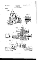
- FIG. 1 is a view of the cutting end of the boring-tool.
- Fig. 2 is a side view of the same, partly in section on the line 2 of Fig. 1 and partly broken away.
- Fig. 3 is a section on the line 3 of Fig. 2.
- Fig. 4 is a perspective 2 5 view of a portion of the head, and Fig. 5 is a perspective View of one of the clamps.
- 1 indicates the stock of the tool, and 2 a' cylindrical head which is screwed onto the stock, as clearly illustrated in Fig. 2.
- the head is provided on its forward side with circular flange-sections 3, having straight forward edges at, which support the cutters 5, the rear sides of the supporting flange-sections being cut away, as at 6,
- the grooves and cutters being preferably rectangular, as shown.
- the cutters are formed of ordinary square rods of tool-steel slightly ground away at their forward ends into suitable shape and of full rectangular section for the remainder of their length.
- the forward or cutting edges of the tools are radial to the center of the stock, and the inner lines of the cutters may be at right angles to these radii.
- the cutter edges ext-end slightly beyond the periphery of the head, so as to give clearance for the supports 3.
- the cutters may he arranged as shown, the first cutting one-third of the total width, the second cutting about two-thirds, and the third cutting the full width, in which case the first cutter should cut deepest, the others following in succession.
- the cutters are held in position by clamps of novel construction.
- Each cutter is provided with a clamp consisting of an L-shaped jaw 8 and a clamping-screw 9, which enters a hole 10 in the head.
- the forward end of the clamp is preferably roughened or provided with teeth 11 to firmly hold the cutter-bars.
- the bearing 12 of the other end is curved in the arc of a circle andis seated in a circular notch 13, formed in the periphery of the head. In this manner the cutters are held firmly and solidly in position.
- the tool is provided on its forward end with a central spindle 14, which enters a hole previously drilled in the plate and guides the tool.
- This spindle is preferably provided with hardened teeth or cutters 15 on its forward end for the purpose of reaming the hole to the exact size of the spindle.
- the spindle is removable from the stock, so that its outters 15 may be readily sharpened or repaired. As shown, it is provided with a threaded shank 16, which screws into an opening 17 in the forward end of the stock.
- cutters are not essential.
- the cutters used are simply ordinary bars of tool-steel having their forward ends ground into shape and tempered. When the cutters are dulled or worn, the grinding can be carried farther back on the bar and the bar advanced. As the cutters are the only parts liable to wear and are inexpensive, the tool is exceedingly durable and economical.
- clamps which adjust themselves accurately to the tools, and the removable centering-spindle having cutters on its forward end.
- a boring-tool comprisinga stock, a head, flanges 8 projecting forwardly from the periphery of the head, grooves in the side of the head registering with the forward faces of the flanges, and means for clamping cutter-bars in said grooves, said flanges being cut away in the rear of the cutter-bars to form recesses for the escape of the cuttings, for the purpose set forth.
- a boring-tool comprising a stock, a head removably connected to the stock, cuttergrooves in the side of said head, cutter-bars in said grooves, forwardly-projecting flanges registering with said grooves, recesses in the rear of said flanges for the escape of the cuttings, cutter-bar clamps, and a centering-spindle detachably inserted in the forward end of the stock.
- a boring-tool comprising astock, a head, grooves in said head, cutter bars in said grooves, and clamps for holding said bars, each clam p comprising an L-shaped jaw having one straight face arranged to rest upon the cutter-bar and a rounded end or surface arranged to rest upon the head, whereby the jaw may seat itself securely upon the cutterbar.
Landscapes
- Engineering & Computer Science (AREA)
- Mechanical Engineering (AREA)
- Earth Drilling (AREA)
Description
No. 687,724. Patented Dec. 3, l90l.
J. F. CADELL.
some TOOL.
lication filed June 21, 1899 mummmn mmum UNITED STATES PATENT Orrrcief.
JOHN F. CADELL, OF BALTIMORE, MARYLAND,
ASSIGNOR TO OTT. MER- OF DELAWARE.
BORING-TOOL.
SPECIFICATION forming part of Letters Patent No.
687,724, dated December 1-- Applioation filed June 21, 1899. Serial No. 721,363. No model.)
To all whom it may concern..-
Be it known that I, JOHN F. CADELL, a citizen of the United States, residing at the city of Baltimore, State of Maryland, have invented certain new and useful Improvements in Boring-Tools, of which the following is a specification.
My invention relates to tools for boring holes in metal plates, and particularly for boring boiler-plates to receive the tubes.
The object of the invention is to provide a boring-tool of this class which is simple in construction and very elfective in operation and in which inexpensive cutters formed I 5 from ordinary bars of tool-steel may be used.
The invention will be described in detail in the following specification, reference being had to the accompanying drawings, in which- Figure 1 is a view of the cutting end of the boring-tool. Fig. 2 is a side view of the same, partly in section on the line 2 of Fig. 1 and partly broken away. Fig. 3is a section on the line 3 of Fig. 2. Fig. 4 is a perspective 2 5 view of a portion of the head, and Fig. 5 is a perspective View of one of the clamps.
In the drawings, 1 indicates the stock of the tool, and 2 a' cylindrical head which is screwed onto the stock, as clearly illustrated in Fig. 2. The head is provided on its forward side with circular flange-sections 3, having straight forward edges at, which support the cutters 5, the rear sides of the supporting flange-sections being cut away, as at 6,
3 5 and a considerable space left between the rear of each support and the forward side of the succeeding cutter to provide ample room for the escape of the cuttings. In the periphery of the head there are a plurality of grooves 7 adapted to receive the cutters 5,
'the grooves and cutters being preferably rectangular, as shown. The cutters are formed of ordinary square rods of tool-steel slightly ground away at their forward ends into suitable shape and of full rectangular section for the remainder of their length. The forward or cutting edges of the tools are radial to the center of the stock, and the inner lines of the cutters may be at right angles to these radii. 5c The cutter edges ext-end slightly beyond the periphery of the head, so as to give clearance for the supports 3. The cutters may he arranged as shown, the first cutting one-third of the total width, the second cutting about two-thirds, and the third cutting the full width, in which case the first cutter should cut deepest, the others following in succession.
The cutters are held in position by clamps of novel construction. Each cutter is provided with a clamp consisting of an L-shaped jaw 8 and a clamping-screw 9, which enters a hole 10 in the head. The forward end of the clamp is preferably roughened or provided with teeth 11 to firmly hold the cutter-bars. In order to permit the forward end to be seated accurately and across its entire surface on the cutter-bar, the bearing 12 of the other end is curved in the arc of a circle andis seated in a circular notch 13, formed in the periphery of the head. In this manner the cutters are held firmly and solidly in position.
The tool is provided on its forward end with a central spindle 14, which enters a hole previously drilled in the plate and guides the tool. This spindle is preferably provided with hardened teeth or cutters 15 on its forward end for the purpose of reaming the hole to the exact size of the spindle. The spindle is removable from the stock, so that its outters 15 may be readily sharpened or repaired. As shown, it is provided with a threaded shank 16, which screws into an opening 17 in the forward end of the stock.
One of the principal advantages of my invention is that specially-formed cutters are not essential. The cutters used are simply ordinary bars of tool-steel having their forward ends ground into shape and tempered. When the cutters are dulled or worn, the grinding can be carried farther back on the bar and the bar advanced. As the cutters are the only parts liable to wear and are inexpensive, the tool is exceedingly durable and economical.
Other valuable features of the invention are the clamps, which adjust themselves accurately to the tools, and the removable centering-spindle having cutters on its forward end.
Having described my invention, What I 7 claim, and desire to secure by Letters Pat ent, is-
1. A boring-tool comprisinga stock, a head, flanges 8 projecting forwardly from the periphery of the head, grooves in the side of the head registering with the forward faces of the flanges, and means for clamping cutter-bars in said grooves, said flanges being cut away in the rear of the cutter-bars to form recesses for the escape of the cuttings, for the purpose set forth.
2. A boring-tool comprising a stock, a head removably connected to the stock, cuttergrooves in the side of said head, cutter-bars in said grooves, forwardly-projecting flanges registering with said grooves, recesses in the rear of said flanges for the escape of the cuttings, cutter-bar clamps, and a centering-spindle detachably inserted in the forward end of the stock.
3. A boring-tool comprising astock, a head, grooves in said head, cutter bars in said grooves, and clamps for holding said bars, each clam p comprising an L-shaped jaw having one straight face arranged to rest upon the cutter-bar and a rounded end or surface arranged to rest upon the head, whereby the jaw may seat itself securely upon the cutterbar.
4. The combination with the stock, the head having a series of cutter-bar grooves and a series of clamp-bearing recesses, and the cutter-bars in said grooves, of clamps for holding said bars each consisting of an L-shaped jaw having a rounded end adapted to rest in one of the recesses in the head, and a flat face arranged to engage with the cutter-bar, as set forth.
In testimony whereof I affix my signature in presence of two witnesses.
JOHN F. CADELL.
Witnesses:
WILLIAM G. HOOFNAGLE, ELDRIDGE E. HENDERSON.
Priority Applications (1)
| Application Number | Priority Date | Filing Date | Title |
|---|---|---|---|
| US72135399A US687724A (en) | 1899-06-21 | 1899-06-21 | Boring-tool. |
Applications Claiming Priority (1)
| Application Number | Priority Date | Filing Date | Title |
|---|---|---|---|
| US72135399A US687724A (en) | 1899-06-21 | 1899-06-21 | Boring-tool. |
Publications (1)
| Publication Number | Publication Date |
|---|---|
| US687724A true US687724A (en) | 1901-12-03 |
Family
ID=2756266
Family Applications (1)
| Application Number | Title | Priority Date | Filing Date |
|---|---|---|---|
| US72135399A Expired - Lifetime US687724A (en) | 1899-06-21 | 1899-06-21 | Boring-tool. |
Country Status (1)
| Country | Link |
|---|---|
| US (1) | US687724A (en) |
Cited By (6)
| Publication number | Priority date | Publication date | Assignee | Title |
|---|---|---|---|---|
| US2427816A (en) * | 1944-05-08 | 1947-09-23 | Robert H Clark | Tool |
| US2437364A (en) * | 1944-05-05 | 1948-03-09 | Robert H Clark | Drill and countersink tool |
| US2444099A (en) * | 1945-06-26 | 1948-06-29 | Camloc Fastener Corp | Hole-cutting saw |
| US2463063A (en) * | 1943-05-07 | 1949-03-01 | Robert H Clark | Cutting tool |
| US2722856A (en) * | 1952-04-21 | 1955-11-08 | John G Dixon | Annular sweep drill or hole cutter |
| US3591306A (en) * | 1968-01-12 | 1971-07-06 | Bbc Brown Boveri & Cie | Core borer |
-
1899
- 1899-06-21 US US72135399A patent/US687724A/en not_active Expired - Lifetime
Cited By (6)
| Publication number | Priority date | Publication date | Assignee | Title |
|---|---|---|---|---|
| US2463063A (en) * | 1943-05-07 | 1949-03-01 | Robert H Clark | Cutting tool |
| US2437364A (en) * | 1944-05-05 | 1948-03-09 | Robert H Clark | Drill and countersink tool |
| US2427816A (en) * | 1944-05-08 | 1947-09-23 | Robert H Clark | Tool |
| US2444099A (en) * | 1945-06-26 | 1948-06-29 | Camloc Fastener Corp | Hole-cutting saw |
| US2722856A (en) * | 1952-04-21 | 1955-11-08 | John G Dixon | Annular sweep drill or hole cutter |
| US3591306A (en) * | 1968-01-12 | 1971-07-06 | Bbc Brown Boveri & Cie | Core borer |
Similar Documents
| Publication | Publication Date | Title |
|---|---|---|
| US2275327A (en) | Tool holder | |
| US687724A (en) | Boring-tool. | |
| US1365683A (en) | Combination rounding-tool | |
| US2324603A (en) | Combination toolholder for lathes | |
| US136138A (en) | Improvement in hollow augers | |
| US2770028A (en) | Broach with multiple small cutting units | |
| US1778260A (en) | Milling cutter | |
| US2492797A (en) | Milling cutter | |
| US303053A (en) | Combined drsll and countersink | |
| US213691A (en) | Improvement in tools for cutting pipes | |
| US700736A (en) | Milling-machine cutter. | |
| US909401A (en) | Reamer. | |
| US1861787A (en) | Cutter for woodworking machines | |
| US293494A (en) | Gutter-head | |
| US201908A (en) | Improvement in combined auger and reamer | |
| US134477A (en) | Improvement in tubexcutters | |
| US3489422A (en) | Tool adjustment assemblage for drive shafts | |
| US605422A (en) | Metals | |
| US553280A (en) | Rotary cutter for planing-machines | |
| US417776A (en) | Thomas eynon | |
| US547455A (en) | Cutter-head | |
| US662492A (en) | Cutting-tool. | |
| US486269A (en) | Rotary cutter for woodwork | |
| US450879A (en) | Reamer | |
| US238322A (en) | John f |