US6874664B1 - Push-pull dispenser with folding fingers - Google Patents
Push-pull dispenser with folding fingers Download PDFInfo
- Publication number
- US6874664B1 US6874664B1 US10/163,203 US16320302A US6874664B1 US 6874664 B1 US6874664 B1 US 6874664B1 US 16320302 A US16320302 A US 16320302A US 6874664 B1 US6874664 B1 US 6874664B1
- Authority
- US
- United States
- Prior art keywords
- stem
- push
- base portion
- top wall
- cap
- Prior art date
- Legal status (The legal status is an assumption and is not a legal conclusion. Google has not performed a legal analysis and makes no representation as to the accuracy of the status listed.)
- Expired - Lifetime, expires
Links
Images


Classifications
-
- B—PERFORMING OPERATIONS; TRANSPORTING
- B65—CONVEYING; PACKING; STORING; HANDLING THIN OR FILAMENTARY MATERIAL
- B65D—CONTAINERS FOR STORAGE OR TRANSPORT OF ARTICLES OR MATERIALS, e.g. BAGS, BARRELS, BOTTLES, BOXES, CANS, CARTONS, CRATES, DRUMS, JARS, TANKS, HOPPERS, FORWARDING CONTAINERS; ACCESSORIES, CLOSURES, OR FITTINGS THEREFOR; PACKAGING ELEMENTS; PACKAGES
- B65D47/00—Closures with filling and discharging, or with discharging, devices
- B65D47/04—Closures with discharging devices other than pumps
- B65D47/20—Closures with discharging devices other than pumps comprising hand-operated members for controlling discharge
- B65D47/24—Closures with discharging devices other than pumps comprising hand-operated members for controlling discharge with poppet valves or lift valves, i.e. valves opening or closing a passageway by a relative motion substantially perpendicular to the plane of the seat
- B65D47/241—Closures with discharging devices other than pumps comprising hand-operated members for controlling discharge with poppet valves or lift valves, i.e. valves opening or closing a passageway by a relative motion substantially perpendicular to the plane of the seat the valve being opened or closed by actuating a cap-like element
- B65D47/243—Closures with discharging devices other than pumps comprising hand-operated members for controlling discharge with poppet valves or lift valves, i.e. valves opening or closing a passageway by a relative motion substantially perpendicular to the plane of the seat the valve being opened or closed by actuating a cap-like element moving linearly, i.e. without rotational motion
-
- B—PERFORMING OPERATIONS; TRANSPORTING
- B65—CONVEYING; PACKING; STORING; HANDLING THIN OR FILAMENTARY MATERIAL
- B65D—CONTAINERS FOR STORAGE OR TRANSPORT OF ARTICLES OR MATERIALS, e.g. BAGS, BARRELS, BOTTLES, BOXES, CANS, CARTONS, CRATES, DRUMS, JARS, TANKS, HOPPERS, FORWARDING CONTAINERS; ACCESSORIES, CLOSURES, OR FITTINGS THEREFOR; PACKAGING ELEMENTS; PACKAGES
- B65D51/00—Closures not otherwise provided for
- B65D51/18—Arrangements of closures with protective outer cap-like covers or of two or more co-operating closures
-
- B—PERFORMING OPERATIONS; TRANSPORTING
- B65—CONVEYING; PACKING; STORING; HANDLING THIN OR FILAMENTARY MATERIAL
- B65D—CONTAINERS FOR STORAGE OR TRANSPORT OF ARTICLES OR MATERIALS, e.g. BAGS, BARRELS, BOTTLES, BOXES, CANS, CARTONS, CRATES, DRUMS, JARS, TANKS, HOPPERS, FORWARDING CONTAINERS; ACCESSORIES, CLOSURES, OR FITTINGS THEREFOR; PACKAGING ELEMENTS; PACKAGES
- B65D2251/00—Details relating to container closures
- B65D2251/0003—Two or more closures
- B65D2251/0006—Upper closure
- B65D2251/0015—Upper closure of the 41-type
-
- B—PERFORMING OPERATIONS; TRANSPORTING
- B65—CONVEYING; PACKING; STORING; HANDLING THIN OR FILAMENTARY MATERIAL
- B65D—CONTAINERS FOR STORAGE OR TRANSPORT OF ARTICLES OR MATERIALS, e.g. BAGS, BARRELS, BOTTLES, BOXES, CANS, CARTONS, CRATES, DRUMS, JARS, TANKS, HOPPERS, FORWARDING CONTAINERS; ACCESSORIES, CLOSURES, OR FITTINGS THEREFOR; PACKAGING ELEMENTS; PACKAGES
- B65D2251/00—Details relating to container closures
- B65D2251/0003—Two or more closures
- B65D2251/0068—Lower closure
- B65D2251/0087—Lower closure of the 47-type
Definitions
- the present invention relates generally to push-pull type dispenser. More specifically, the present invention relates to a push-pull type dispenser having a folding finger positioned on an inner surface of a slidable dispensing cap, the folding finger being designed to inhibit removal of the slidable dispensing cap from the dispenser.
- Typical push-pull designs have often used interference beads disposed along an inner surface of the sliding cap and an outer surface of the stem to prevent the cap from being pulled from the stem. Due to the rounded design of typical interference beads, for example the ribs shown in U.S. Pat. No. 5,328,063, those cap beads can often be pulled over the stem interference bead with little force. This is due to the resultant force caused by a combination of the vertical pulling force by a user and contact along angled surfaces of the interference beads which forces the cap to deflect outward and over the stem bead.
- a push-pull dispenser design having a folding finger on a slidable dispensing cap wherein the folding finger has a horizontal surface which contacts a horizontal surface of an interference bead such that the sliding cap is inhibited from being removed.
- the push-pull dispenser comprises a base portion having an annular sidewall including an outer surface and an inner surface.
- the inner surface of the sidewall may have a helical thread circumferentially extending about the inner surface to engage a neck finish.
- the base portion further comprises a base portion top wall having a dispensing orifice therein for dispensing fluid from within a container.
- the base portion top wall also has a flexible folding seal element for compressively sealing against a container top wall.
- a stem Extending above the base portion top wall and circumscribing the base portion dispensing orifice is a stem.
- the stem has a hollow cylindrical shape and is in fluid communication with the base portion and a container disposed therebeneath.
- a stem lug At an upper end of the stem is a stem lug which, in section, may have four sides including a substantially horizontal lower surface and a tapered or beveled upper surface.
- the stem lug may be molded in a first upper position and pushed down to a lower position for use.
- a flow diverter Centrally disposed within an upper portion of the stem. The flow diverter works in cooperation with a slidable dispensing cap to open and close the fluid communication path through the push-pull dispenser.
- a slidable dispensing cap Slidably connected to the stem is a slidable dispensing cap, being substantially cylindrical in shape and having a finger rib circumscribing an upper portion of the cap.
- the cap further comprises an upper surface or cap top wall having a cap-dispensing aperture therein.
- the cap dispensing aperture is in fluid communication with the stem and a container disposed beneath the dispenser.
- an annular valve finger which engages the stem.
- At a lower end of the slidable dispensing cap is at least one folding finger.
- the at least one folding finger may be either a continuous folding finger or a plurality of folding fingers.
- the at least one folding finger have a substantially horizontal upper surface which engages the lower horizontal rib surface.
- the at least one folding finger is preferably disposed in an upwardly and inwardly extending manner and between the inner surface of the slidable dispensing cap and the outer surface of the stem.
- a flow diverter is centrally disposed in the stem.
- This design defines an inner fluid communication path through the base portion, neck, stem, and cap dispensing aperture.
- FIG. 1 shows an assembly view of the push-pull dispenser of the present invention
- FIG. 2 shows a top view of the push-pull dispenser of FIG. 1 ;
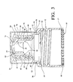
- FIG. 3 shows a sectional view of the push-pull dispenser of FIG. 1 in the closed position
- FIG. 4 shows a sectional view of the push-pull dispenser of FIG. 1 in the open position
- FIG. 5 shows a sectional view of the dispenser and a typical container used with the dispenser
- FIG. 6 shows a perspective view of the push-pull dispenser of the present invention having a continuous stem lug and continuous folding finger;
- FIG. 7 shows a perspective view of the push-pull dispenser of the present invention having a plurality of stem lugs and a plurality of folding fingers.
- the dispenser 10 may be formed of some rigid or semi-rigid polymeric material and may be made of polypropylene in an injection molding process.
- the dispenser 10 comprises a base portion 12 having a base portion top wall 14 and a base portion skirt 16 depending from a peripheral edge of the base portion top wall 14 .
- the base portion 12 is preferably cylindrical in shape with a lower edge 17 defining an opening 18 for placing the dispenser 10 on a container 80 .
- the skirt 16 may have a knurling 19 along an outer surface of the base portion 12 for aid in rotating the dispenser 10 to either an open or closed position.
- a helical thread 20 for threadable engagement with the helical thread or neck finish 20 of a container neck 82 as seen in FIG. 5 .
- the neck finish or thread 20 may be of varying pitch and size depending on the intended use, as will be understood by one of ordinary skill in the art.
- the thread 20 may have a plurality of configurations including single helix, double helix, and triple helix or other multiple lead thread design.
- the seal 24 may be a plug seal, a reverse taper plug seal, or as depicted in FIGS. 3 , 4 a folding element seal 24 .
- the folding element seal 24 compressively seals against a container top wall 84 as the dispenser 10 is threadably attached to the container neck 82 .
- a plug seal may be used which sealably engages the container neck.
- a dispensing orifice 22 which is in fluid communication with the container 80 when the dispenser is threadably connected to the neck finish.
- the dispensing orifice 22 may also be in fluid communication with neck 26 .
- the neck 26 extends circumferentially about the dispensing orifice 22 and extends upwardly having a hollow inner portion therein defining a fluid communication path 28 .
- the neck 26 may have a groove 30 extending circumferentially about the neck 26 , as best seen in FIGS. 3 , 4 , which defines a neck bead 32 extending radially outward above the groove 30 and circumscribing the neck 26 .
- the neck bead 32 may operably engage an overcap bead 72 in order to maintain an overcap 70 in a closed position.
- the design of the present invention does not require a neck as the stem may extend to the base portion or the three elements stem, neck, and base may be integrated into a single structure.
- the inventive aspects described herein are considered to incorporate such alternative designs.
- the stem 38 may be substantially cylindrical in shape and has a hollow portion therein further defining the fluid communication path 28 .
- a flow diverter 42 which is connected to the cylindrically shaped inner sidewalls of the stem 38 .
- the flow diverter 42 is centrally located in the stem 38 and preferably is connected to the stem 38 by three stem ribs 39 which are spaced apart about 120 degrees.
- the flow diverter 42 has a diameter less than the inner diameter of the stem 38 such that the fluid communication path 28 is not completely closed. As shown in FIGS.
- the at least one stem lug 44 connected to an upper portion of the stem 38 is at least one stem lug 44 which extends continuously about the circumference of the stem 38 .
- the at least one stem lug 44 may be interrupted by a plurality of slits forming a plurality of stem lugs 44 .
- the at least one stem lug 44 when viewed in section, may be constructed of four protrusions, however the at least one stem lug 44 may be a plurality of shapes.
- the at least one stem lug 44 may be connected to the stem 38 near an upper portion of the stem lug 44 .
- the at least one stem lug 44 may be molded as an abutment or protrusion in the position shown or molded as a folding protrusion with folding hinge line in an upwardly extending position and pushed or rotated downward during assembly.
- the at least one stem lug 44 most preferably has a horizontal lowermost surface which abuts a horizontal surface 61 of a folding finger 60 .
- An upper surface of the at least one stem lug 44 is preferably tapered so that a folding finger 60 of the slidable dispensing cap 50 can more easily pass over the at least one stem lug 44 when the slidable dispensing cap 50 is applied to the stem 38 .
- the slidable dispensing cap 50 has a cylindrical sidewall 52 having a slightly larger diameter than the stem 38 and stem lug 44 connected thereto which allows axial vertical sliding of the slidable dispensing cap 50 along the stem 38 .
- Disposed on an upper portion of the sidewall 52 may be a finger rib 54 circumscribing the sidewall 52 .
- the finger rib 54 aids a user in gripping the slidable dispensing cap 50 and moving the cap 50 between a closed and an open position.
- Extending radially inward from above the finger rib 54 is a cap top wall 56 .
- a cap-dispensing aperture 58 Centrally disposed in the cap top wall 56 is a cap-dispensing aperture 58 .
- the cap-dispensing aperture 58 is disposed above and aligned with the flow diverter 42 .
- the cap-dispensing aperture 58 may be defined by an annular valve finger 59 but any opening within the cap may suffice. As shown in FIGS. 3 , 4 the annular valve finger 59 and flow diverter 42 together form a valve wherein vertical movement of the cap 50 either opens or closes the dispensing aperture 58 .
- an upward movement of the cap 50 causes the annular valve finger 59 to disengage the flow diverter 42 revealing a fluid path 28 through the cap dispensing aperture 58 while a downward movement causes the annular valve finger 59 to engage the flow diverter 42 closing the fluid path 28 through the cap-dispensing aperture 58 .
- the at least one folding finger 60 may be a continuous finger extending about the cap 50 as shown in FIG. 7 or a plurality of folding fingers 60 defined by a plurality of interruptions in the continuous folding finger as shown in FIG. 8 .
- the at least one folding finger 60 has four sides including a hinge line or tapered surface 62 .
- the at least one folding finger 60 also includes an upper horizontal or abutment surface which engages the lower horizontal surface 45 of the stem lug 44 . The contact of two horizontal surfaces inhibits outward deflection of the slidable dispensing cap 50 thus preventing the cap 50 from sliding over stem lug 44 .
- the hinge line or tapered surface 62 along with the bevel formed on the outer peripheral edge of the stem lug 44 , in combination, allow the folding finger 60 to pass over the stem lug 44 when the cap 50 is applied to the stem 38 .
- 5 frangibly connected along a lower peripheral edge of the base portion 12 may be a tamper-indicating ring 66 .
- the tamper-indicating ring 66 may engage a container neck bead 86 when the dispenser is placed on a container 80 . If the tamper indicating ring 66 is loose or detached a user will be forewarned that the contents of the container 80 may have been tampered with.
- an overcap 70 is shown positioned over the slidable dispensing cap 50 .
- the overcap is preferably cup shaped having a top 74 and a cylindrical skirt 76 depending therefrom.
- the overcap 70 has a lower peripheral edge 78 defining an open end. Adjacent the lower peripheral edge 78 and extending radially inward is an overcap bead 72 which extends around the inner surface of the skirt 76 .
- an annular rib 80 may make contact with the slidable dispensing cap 50 so that when the over cap 70 is positioned on the dispenser 10 , the slidable dispensing cap 50 may not slide upwardly and leak container contents therefrom.
- the overcap 70 may be disposed within the groove 30 and beneath the neck bead 32 .
- the overcap bead 72 locks beneath the neck bead 32 to maintain the overcap 70 on the base portion 12 over the slidable dispensing cap 50 .
- the dispenser 10 is preferably formed in an injection molding process.
- the base portion 12 , the neck 26 , and the stem 38 are formed in a first injection molding process while the slidable dispensing cap 50 and overcap 70 may be formed in separate processes.
- the hingeably connected at least one folding finger 60 is pushed upward against the inner portion of the sidewall 52 .
- the lower tapered surface of the at least one folding finger 60 is positioned against the upper tapered surface of the at least one stem lug 44 and pushed downward over the at least one stem lug 44 .
- the hinged connection of the at least one folding finger 60 to the sidewall 52 allows the sidewall 52 to flex outwardly and over the at least one stem lug 44 .
- the slidable dispensing cap 50 may be moved between an upper open position and a lower closed position.
- the annular valve finger 59 disengages the flow diverter 42 opening the fluid communication path 28 from a container through the cap dispensing aperture 58 .
- the annular valve finger 59 engages the flow diverter 42 to close the fluid communication path 28 through the cap dispensing aperture 58 .
- the upper horizontal surface of the folding finger 60 contacts the lower horizontal surface of the at least one stem lug 44 . Since the two contacting surfaces are horizontal, there is no outward force caused by angled surface contact and no resultant force causing outward deflection of the slidable dispensing cap 50 .
Abstract
Description
Claims (21)
Priority Applications (1)
| Application Number | Priority Date | Filing Date | Title |
|---|---|---|---|
| US10/163,203 US6874664B1 (en) | 2002-06-05 | 2002-06-05 | Push-pull dispenser with folding fingers |
Applications Claiming Priority (1)
| Application Number | Priority Date | Filing Date | Title |
|---|---|---|---|
| US10/163,203 US6874664B1 (en) | 2002-06-05 | 2002-06-05 | Push-pull dispenser with folding fingers |
Publications (1)
| Publication Number | Publication Date |
|---|---|
| US6874664B1 true US6874664B1 (en) | 2005-04-05 |
Family
ID=34374809
Family Applications (1)
| Application Number | Title | Priority Date | Filing Date |
|---|---|---|---|
| US10/163,203 Expired - Lifetime US6874664B1 (en) | 2002-06-05 | 2002-06-05 | Push-pull dispenser with folding fingers |
Country Status (1)
| Country | Link |
|---|---|
| US (1) | US6874664B1 (en) |
Cited By (41)
| Publication number | Priority date | Publication date | Assignee | Title |
|---|---|---|---|---|
| US20070158349A1 (en) * | 2004-02-16 | 2007-07-12 | Ewald Schmon | Fluid reservoir for a paint spray gun |
| US20080023502A1 (en) * | 2004-11-16 | 2008-01-31 | Walter Knes | Closure Cap |
| DE202008008600U1 (en) | 2008-05-16 | 2008-10-02 | Mapa Gmbh Gummi- Und Plastikwerke | Push-pull closure for a drinking container |
| US20090050595A1 (en) * | 2007-08-23 | 2009-02-26 | Lackey Robert W | Tethered two piece nestable bottle |
| US20100021089A1 (en) * | 2008-07-24 | 2010-01-28 | Arvizu Gilbert | Re-sealable spigot for a collapsible beverage container |
| US20100084436A1 (en) * | 2008-07-24 | 2010-04-08 | Sports Pouch Beverage Co., Inc. | Re-sealable spigot for a collapsible beverage container |
| US20100163509A1 (en) * | 2008-12-17 | 2010-07-01 | Mauro Andres Canziani Hoffa | Hermetic closing system, additive dispenser, for containers and/or bottles |
| WO2010149965A1 (en) * | 2009-06-22 | 2010-12-29 | Specwaship2007 Ltd | Foldable liquids containers |
| US20110024465A1 (en) * | 2009-07-28 | 2011-02-03 | Thomas Roosel | System for fastening a dispensing pump on the neck of a bottle containing a fluid product |
| US20110046778A1 (en) * | 2003-07-01 | 2011-02-24 | Asteres, Inc. | Method of conducting a sales transaction using a random access and random load dispensing unit |
| US20110137455A1 (en) * | 2003-07-01 | 2011-06-09 | Pinney Linda J | Random Access and Random Load Dispensing Unit |
| US20140197126A1 (en) * | 2011-04-05 | 2014-07-17 | Bericap | Stopper having a sliding plug and comprising multiple distribution holes |
| US8925836B2 (en) | 2008-10-29 | 2015-01-06 | Sata Gmbh & Co. Kg | Gravity cup for a paint sprayer |
| USD740393S1 (en) | 2013-09-27 | 2015-10-06 | Sata Gmbh & Co. Kg | Paint spray gun |
| US9242772B1 (en) * | 2011-05-27 | 2016-01-26 | Michael R. Anderson | Drink-through dispensing capsule with snap in activation chamber |
| US9327301B2 (en) | 2008-03-12 | 2016-05-03 | Jeffrey D. Fox | Disposable spray gun cartridge |
| USD758537S1 (en) | 2014-07-31 | 2016-06-07 | Sata Gmbh & Co. Kg | Paint spray gun rear portion |
| US9409197B2 (en) | 2013-12-18 | 2016-08-09 | Sata Gmbh & Co. Kg | Air nozzle closure for a spray gun |
| USD768820S1 (en) | 2014-09-03 | 2016-10-11 | Sata Gmbh & Co. Kg | Paint spray gun with pattern |
| USD770593S1 (en) | 2014-07-31 | 2016-11-01 | Sata Gmbh & Co. Kg | Paint spray gun |
| US9533317B2 (en) | 2009-07-08 | 2017-01-03 | Sata Gmbh & Co. Kg | Paint spray gun |
| US9782784B2 (en) | 2010-05-28 | 2017-10-10 | Sata Gmbh & Co. Kg | Nozzle head for a spray device |
| US9782785B2 (en) | 2010-12-02 | 2017-10-10 | Sata Gmbh & Co. Kg | Spray gun and accessories |
| US9878336B2 (en) | 2006-12-05 | 2018-01-30 | Sata Gmbh & Co. Kg | Fluid reservoir for a paint spray gun |
| USD821201S1 (en) | 2015-09-21 | 2018-06-26 | S. C. Johnson & Son, Inc. | Container with base |
| USD821203S1 (en) | 2015-09-21 | 2018-06-26 | S. C. Johnson & Son, Inc. | Container with cap and base |
| USD821202S1 (en) | 2015-09-21 | 2018-06-26 | S. C. Johnson & Son, Inc. | Container with cap and base |
| USD830827S1 (en) | 2015-09-21 | 2018-10-16 | S. C. Johnson & Son, Inc. | Container with base |
| US10189037B2 (en) | 2011-06-30 | 2019-01-29 | Sata Gmbh & Co. Kg | Easy-to-clean spray gun, accessories therefor, and mounting and dismounting methods |
| USD858288S1 (en) | 2015-09-21 | 2019-09-03 | S. C. Johnson & Son, Inc. | Container with base |
| US10464076B2 (en) | 2015-12-21 | 2019-11-05 | Sata Gmbh & Co. Kg | Air cap and nozzle assembly for a spray gun, and spray gun |
| US10471449B2 (en) | 2016-08-19 | 2019-11-12 | Sata Gmbh & Co. Kg | Air cap arrangement and spray gun |
| US10702879B2 (en) | 2014-07-31 | 2020-07-07 | Sata Gmbh & Co. Kg | Spray gun manufacturing method, spray gun, spray gun body and cover |
| US10773069B2 (en) | 2014-05-01 | 2020-09-15 | Michael D. Laufer | Medical devices and methods for fluid transfer |
| US10835911B2 (en) | 2016-08-19 | 2020-11-17 | Sata Gmbh & Co. Kg | Trigger for a spray gun and spray gun having same |
| US11034489B2 (en) * | 2019-05-18 | 2021-06-15 | Justin Schmidt | Spill proof pull-push type lid assembly for a beverage bottle |
| US11141747B2 (en) | 2015-05-22 | 2021-10-12 | Sata Gmbh & Co. Kg | Nozzle arrangement for a spray gun |
| US20220312944A1 (en) * | 2019-06-07 | 2022-10-06 | Unslosh Gmbh | Drinking bottle |
| US11801521B2 (en) | 2018-08-01 | 2023-10-31 | Sata Gmbh & Co. Kg | Main body for a spray gun, spray guns, spray gun set, method for producing a main body for a spray gun and method for converting a spray gun |
| US11826771B2 (en) | 2018-08-01 | 2023-11-28 | Sata Gmbh & Co. Kg | Set of nozzles for a spray gun, spray gun system, method for embodying a nozzle module, method for selecting a nozzle module from a set of nozzles for a paint job, selection system and computer program product |
| US11865558B2 (en) | 2018-08-01 | 2024-01-09 | Sata Gmbh & Co. Kg | Nozzle for a spray gun, nozzle set for a spray gun, spray guns and methods for producing a nozzle for a spray gun |
Citations (13)
| Publication number | Priority date | Publication date | Assignee | Title |
|---|---|---|---|---|
| US1920199A (en) * | 1932-09-27 | 1933-08-01 | Charles J Jesnig | Closure for collapsible tubes and the like |
| US1977623A (en) * | 1933-02-20 | 1934-10-23 | William C Biddle | Nonremovable receptacle cap |
| US2017140A (en) * | 1933-10-17 | 1935-10-15 | Worth Charles Eugene | Permanently retained cap for pharmaceutical containers |
| US2582026A (en) | 1946-12-02 | 1952-01-08 | Friedman Max | Closure for container having a neck with a reduced outer portion and a bore, and seals for said bore and said reduced portion |
| US2621832A (en) | 1948-03-30 | 1952-12-16 | Friedman Max | Container closure |
| US5104008A (en) * | 1990-12-03 | 1992-04-14 | Northern Engineering And Plastics Corp. | Resealable bottle cap with push-pull closure |
| US5465876A (en) * | 1994-06-09 | 1995-11-14 | Portola Packaging, Inc. | Container and closure resealable bottle cap with push pull closure |
| US5472120A (en) | 1994-03-31 | 1995-12-05 | Erie Plastics | Bottle with two-stage opening |
| US5588562A (en) | 1994-10-31 | 1996-12-31 | Sander; Dieter | Tamper evident resealable plastic closure |
| US5979716A (en) * | 1998-03-02 | 1999-11-09 | May; Myron R. | Vented container seal with pouring spout |
| US6286733B1 (en) * | 1999-09-30 | 2001-09-11 | Rexam Medical Packaging Inc. | Sliding valve dispenser with overcap |
| US6357635B1 (en) | 1999-09-15 | 2002-03-19 | Loctite Corporation | Dispensing closure assembly |
| US6568566B2 (en) * | 2001-09-21 | 2003-05-27 | Erie Plastics Corporation | Container closure with horizontal and vertical seals |
-
2002
- 2002-06-05 US US10/163,203 patent/US6874664B1/en not_active Expired - Lifetime
Patent Citations (13)
| Publication number | Priority date | Publication date | Assignee | Title |
|---|---|---|---|---|
| US1920199A (en) * | 1932-09-27 | 1933-08-01 | Charles J Jesnig | Closure for collapsible tubes and the like |
| US1977623A (en) * | 1933-02-20 | 1934-10-23 | William C Biddle | Nonremovable receptacle cap |
| US2017140A (en) * | 1933-10-17 | 1935-10-15 | Worth Charles Eugene | Permanently retained cap for pharmaceutical containers |
| US2582026A (en) | 1946-12-02 | 1952-01-08 | Friedman Max | Closure for container having a neck with a reduced outer portion and a bore, and seals for said bore and said reduced portion |
| US2621832A (en) | 1948-03-30 | 1952-12-16 | Friedman Max | Container closure |
| US5104008A (en) * | 1990-12-03 | 1992-04-14 | Northern Engineering And Plastics Corp. | Resealable bottle cap with push-pull closure |
| US5472120A (en) | 1994-03-31 | 1995-12-05 | Erie Plastics | Bottle with two-stage opening |
| US5465876A (en) * | 1994-06-09 | 1995-11-14 | Portola Packaging, Inc. | Container and closure resealable bottle cap with push pull closure |
| US5588562A (en) | 1994-10-31 | 1996-12-31 | Sander; Dieter | Tamper evident resealable plastic closure |
| US5979716A (en) * | 1998-03-02 | 1999-11-09 | May; Myron R. | Vented container seal with pouring spout |
| US6357635B1 (en) | 1999-09-15 | 2002-03-19 | Loctite Corporation | Dispensing closure assembly |
| US6286733B1 (en) * | 1999-09-30 | 2001-09-11 | Rexam Medical Packaging Inc. | Sliding valve dispenser with overcap |
| US6568566B2 (en) * | 2001-09-21 | 2003-05-27 | Erie Plastics Corporation | Container closure with horizontal and vertical seals |
Cited By (60)
| Publication number | Priority date | Publication date | Assignee | Title |
|---|---|---|---|---|
| US20110046778A1 (en) * | 2003-07-01 | 2011-02-24 | Asteres, Inc. | Method of conducting a sales transaction using a random access and random load dispensing unit |
| US9105142B2 (en) | 2003-07-01 | 2015-08-11 | Asteres, Inc. | Random access and random load dispensing unit |
| US8521327B2 (en) | 2003-07-01 | 2013-08-27 | Asteres, Inc. | Random access and random load dispensing unit |
| US8195329B2 (en) | 2003-07-01 | 2012-06-05 | Asteres, Inc. | Method of conducting a sales transaction using a random access and random load dispensing unit |
| US20110137455A1 (en) * | 2003-07-01 | 2011-06-09 | Pinney Linda J | Random Access and Random Load Dispensing Unit |
| US20070158349A1 (en) * | 2004-02-16 | 2007-07-12 | Ewald Schmon | Fluid reservoir for a paint spray gun |
| US7810744B2 (en) * | 2004-02-16 | 2010-10-12 | Sata Gmbh & Co. Kg | Fluid reservoir for a paint spray gun |
| US20080023502A1 (en) * | 2004-11-16 | 2008-01-31 | Walter Knes | Closure Cap |
| US9878336B2 (en) | 2006-12-05 | 2018-01-30 | Sata Gmbh & Co. Kg | Fluid reservoir for a paint spray gun |
| US20090050595A1 (en) * | 2007-08-23 | 2009-02-26 | Lackey Robert W | Tethered two piece nestable bottle |
| US9327301B2 (en) | 2008-03-12 | 2016-05-03 | Jeffrey D. Fox | Disposable spray gun cartridge |
| DE102008023904B4 (en) * | 2008-05-16 | 2010-07-29 | Mapa Gmbh Gummi- Und Plastikwerke | Push-pull closure for a drinking container |
| CN102089218B (en) * | 2008-05-16 | 2013-06-12 | 玛帕有限公司 | Push-pull closure for a drink container |
| US9522769B2 (en) | 2008-05-16 | 2016-12-20 | Mapa Gmbh | Push-pull closure for a drink container |
| DE202008008600U1 (en) | 2008-05-16 | 2008-10-02 | Mapa Gmbh Gummi- Und Plastikwerke | Push-pull closure for a drinking container |
| DE102008023904A1 (en) | 2008-05-16 | 2009-11-26 | Mapa Gmbh Gummi- Und Plastikwerke | Push-pull closure for a drinking container |
| RU2481259C2 (en) * | 2008-05-16 | 2013-05-10 | МАПА ГмбХ | Push pull lock for drinking reservoir |
| US20100021089A1 (en) * | 2008-07-24 | 2010-01-28 | Arvizu Gilbert | Re-sealable spigot for a collapsible beverage container |
| US8459512B2 (en) * | 2008-07-24 | 2013-06-11 | Sports Pouch Beverage Co., Inc. | Re-sealable spigot for a collapsible beverage container |
| US8474665B2 (en) * | 2008-07-24 | 2013-07-02 | Sports Pouch Beverage Co., Inc. | Re-sealable spigot for a collapsible beverage container |
| US20100084436A1 (en) * | 2008-07-24 | 2010-04-08 | Sports Pouch Beverage Co., Inc. | Re-sealable spigot for a collapsible beverage container |
| US8925836B2 (en) | 2008-10-29 | 2015-01-06 | Sata Gmbh & Co. Kg | Gravity cup for a paint sprayer |
| US20100163509A1 (en) * | 2008-12-17 | 2010-07-01 | Mauro Andres Canziani Hoffa | Hermetic closing system, additive dispenser, for containers and/or bottles |
| US8356711B2 (en) * | 2008-12-17 | 2013-01-22 | Mauro Andres Canziani Hoffa | Hermetic closing system, additive dispenser, for containers and/or bottles |
| WO2010149965A1 (en) * | 2009-06-22 | 2010-12-29 | Specwaship2007 Ltd | Foldable liquids containers |
| US9533317B2 (en) | 2009-07-08 | 2017-01-03 | Sata Gmbh & Co. Kg | Paint spray gun |
| US8544691B2 (en) * | 2009-07-28 | 2013-10-01 | Rexam Dispensing Systems S.A.S. | System for fastening a dispensing pump on the neck of a bottle containing a fluid product |
| US20110024465A1 (en) * | 2009-07-28 | 2011-02-03 | Thomas Roosel | System for fastening a dispensing pump on the neck of a bottle containing a fluid product |
| US9782784B2 (en) | 2010-05-28 | 2017-10-10 | Sata Gmbh & Co. Kg | Nozzle head for a spray device |
| US9782785B2 (en) | 2010-12-02 | 2017-10-10 | Sata Gmbh & Co. Kg | Spray gun and accessories |
| US9428308B2 (en) * | 2011-04-05 | 2016-08-30 | Bericap | Stopper having a sliding plug and comprising multiple distribution holes |
| US20140197126A1 (en) * | 2011-04-05 | 2014-07-17 | Bericap | Stopper having a sliding plug and comprising multiple distribution holes |
| US9242772B1 (en) * | 2011-05-27 | 2016-01-26 | Michael R. Anderson | Drink-through dispensing capsule with snap in activation chamber |
| US10189037B2 (en) | 2011-06-30 | 2019-01-29 | Sata Gmbh & Co. Kg | Easy-to-clean spray gun, accessories therefor, and mounting and dismounting methods |
| USD740393S1 (en) | 2013-09-27 | 2015-10-06 | Sata Gmbh & Co. Kg | Paint spray gun |
| US9409197B2 (en) | 2013-12-18 | 2016-08-09 | Sata Gmbh & Co. Kg | Air nozzle closure for a spray gun |
| US11724086B2 (en) | 2014-05-01 | 2023-08-15 | Michael D. Laufer | Medical devices and methods for fluid transfer |
| US10773069B2 (en) | 2014-05-01 | 2020-09-15 | Michael D. Laufer | Medical devices and methods for fluid transfer |
| US10702879B2 (en) | 2014-07-31 | 2020-07-07 | Sata Gmbh & Co. Kg | Spray gun manufacturing method, spray gun, spray gun body and cover |
| USD770593S1 (en) | 2014-07-31 | 2016-11-01 | Sata Gmbh & Co. Kg | Paint spray gun |
| USD798419S1 (en) | 2014-07-31 | 2017-09-26 | Sata Gmbh & Co. Kg | Paint spray gun |
| USD835235S1 (en) | 2014-07-31 | 2018-12-04 | Sata Gmbh & Co. Kg | Paint spray gun |
| USD758537S1 (en) | 2014-07-31 | 2016-06-07 | Sata Gmbh & Co. Kg | Paint spray gun rear portion |
| USD768820S1 (en) | 2014-09-03 | 2016-10-11 | Sata Gmbh & Co. Kg | Paint spray gun with pattern |
| US11141747B2 (en) | 2015-05-22 | 2021-10-12 | Sata Gmbh & Co. Kg | Nozzle arrangement for a spray gun |
| USD830827S1 (en) | 2015-09-21 | 2018-10-16 | S. C. Johnson & Son, Inc. | Container with base |
| USD821203S1 (en) | 2015-09-21 | 2018-06-26 | S. C. Johnson & Son, Inc. | Container with cap and base |
| USD858288S1 (en) | 2015-09-21 | 2019-09-03 | S. C. Johnson & Son, Inc. | Container with base |
| USD821201S1 (en) | 2015-09-21 | 2018-06-26 | S. C. Johnson & Son, Inc. | Container with base |
| USD846382S1 (en) | 2015-09-21 | 2019-04-23 | S. C. Johnson & Son, Inc. | Container base |
| USD821202S1 (en) | 2015-09-21 | 2018-06-26 | S. C. Johnson & Son, Inc. | Container with cap and base |
| USD846397S1 (en) | 2015-09-21 | 2019-04-23 | S.C. Johnson & Son, Inc. | Container with base |
| US10464076B2 (en) | 2015-12-21 | 2019-11-05 | Sata Gmbh & Co. Kg | Air cap and nozzle assembly for a spray gun, and spray gun |
| US10835911B2 (en) | 2016-08-19 | 2020-11-17 | Sata Gmbh & Co. Kg | Trigger for a spray gun and spray gun having same |
| US10471449B2 (en) | 2016-08-19 | 2019-11-12 | Sata Gmbh & Co. Kg | Air cap arrangement and spray gun |
| US11801521B2 (en) | 2018-08-01 | 2023-10-31 | Sata Gmbh & Co. Kg | Main body for a spray gun, spray guns, spray gun set, method for producing a main body for a spray gun and method for converting a spray gun |
| US11826771B2 (en) | 2018-08-01 | 2023-11-28 | Sata Gmbh & Co. Kg | Set of nozzles for a spray gun, spray gun system, method for embodying a nozzle module, method for selecting a nozzle module from a set of nozzles for a paint job, selection system and computer program product |
| US11865558B2 (en) | 2018-08-01 | 2024-01-09 | Sata Gmbh & Co. Kg | Nozzle for a spray gun, nozzle set for a spray gun, spray guns and methods for producing a nozzle for a spray gun |
| US11034489B2 (en) * | 2019-05-18 | 2021-06-15 | Justin Schmidt | Spill proof pull-push type lid assembly for a beverage bottle |
| US20220312944A1 (en) * | 2019-06-07 | 2022-10-06 | Unslosh Gmbh | Drinking bottle |
Similar Documents
| Publication | Publication Date | Title |
|---|---|---|
| US6874664B1 (en) | Push-pull dispenser with folding fingers | |
| US6039218A (en) | Tamper-evident closure with abutment | |
| US4709823A (en) | Tamper evident bottle or package closure | |
| US5794803A (en) | Child-resistant measuring cup closure and dispensing container | |
| US6041982A (en) | Beverage container with cap and spout | |
| US7828166B1 (en) | Dispensing closure with child resistant feature | |
| US3318496A (en) | Container closure with axial plug | |
| US7988004B1 (en) | Dispensing closure with tamper evident device | |
| US6543650B1 (en) | Double shell dispenser | |
| US5909827A (en) | Non-spill bottle cap | |
| EP3950528B1 (en) | Capping device intended to be fixed on the neck of a container | |
| US6910607B2 (en) | Cover for dispensing closure with pressure actuated valve | |
| US6299038B1 (en) | Telescoping twist closure | |
| CA2584348A1 (en) | Child-resistant dispensing closure, package and method of manufacture | |
| RU2254275C2 (en) | Pouring apparatus and cap with built-in pouring apparatus | |
| US6758376B1 (en) | Edge seal closure | |
| US10450113B2 (en) | Relating to closures | |
| EP3842358B1 (en) | Capping device intended to be fixed to a neck of a container | |
| US4154354A (en) | Safety container closures | |
| US2104413A (en) | Closure for containers | |
| US3120908A (en) | One-piece plastic resealing spout | |
| US5419467A (en) | Two-piece pouring spout with dome-shaped nozzle | |
| WO2007121430A2 (en) | Tamper-evident closure valve | |
| US3895731A (en) | Closure for receptacles | |
| CN115991341A (en) | Flavoring bottle and method for dispensing substances from container |
Legal Events
| Date | Code | Title | Description |
|---|---|---|---|
| AS | Assignment |
Owner name: REXAM MEDICAL PACKAGING INC., INDIANA Free format text: ASSIGNMENT OF ASSIGNORS INTEREST;ASSIGNOR:MONTGOMERY, GARY V.;REEL/FRAME:012968/0706 Effective date: 20020604 |
|
| STCF | Information on status: patent grant |
Free format text: PATENTED CASE |
|
| FPAY | Fee payment |
Year of fee payment: 4 |
|
| AS | Assignment |
Owner name: REXAM CLOSURES AND CONTAINERS INC., NORTH CAROLINA Free format text: ASSIGNMENT OF ASSIGNORS INTEREST;ASSIGNOR:REXAM MEDICAL PACKAGING INC.;REEL/FRAME:028548/0483 Effective date: 20110815 |
|
| AS | Assignment |
Owner name: REXAM CLOSURES LLC, NORTH CAROLINA Free format text: ASSIGNMENT OF ASSIGNORS INTEREST;ASSIGNOR:REXAM CLOSURES AND CONTAINERS, INC.;REEL/FRAME:028680/0204 Effective date: 20110815 |
|
| AS | Assignment |
Owner name: BERRY PLASTICS CORPORATION, INDIANA Free format text: ASSIGNMENT OF ASSIGNORS INTEREST;ASSIGNOR:REXAM CLOSURES LLC;REEL/FRAME:028715/0215 Effective date: 20120529 |
|
| FPAY | Fee payment |
Year of fee payment: 8 |
|
| FPAY | Fee payment |
Year of fee payment: 12 |
|
| AS | Assignment |
Owner name: CREDIT SUISSE AG, CAYMAN ISLANDS BRANCH, NEW YORK Free format text: FIRST LIEN INTELLECTUAL PROPERTY SECURITY AGREEMENT;ASSIGNORS:AVINTIV SPECIALTY MATERIALS INC.;BERRY FILM PRODUCTS COMPANY, INC.;BERRY GLOBAL FILMS, LLC;AND OTHERS;REEL/FRAME:049121/0864 Effective date: 20190501 Owner name: BANK OF AMERICA, NORTH CAROLINA Free format text: FIRST LIEN INTELLECTUAL PROPERTY SECURITY AGREEMENT;ASSIGNORS:AVINTIV SPECIALTY MATERIALS INC.;BERRY FILM PRODUCTS COMPANY, INC.;BERRY GLOBAL FILMS, LLC;AND OTHERS;REEL/FRAME:049121/0864 Effective date: 20190501 |
|
| AS | Assignment |
Owner name: U.S. BANK NATIONAL ASSOCIATION, AS COLLATERAL AGEN Free format text: FIRST LIEN PATENT SECURITY AGREEMENT;ASSIGNORS:BERRY GLOBAL, INC.;BERRY FILM PRODUCTS COMPANY, INC.;BPREX HEALTHCARE PACKAGING INC.;AND OTHERS;REEL/FRAME:049671/0171 Effective date: 20190701 Owner name: U.S. BANK NATIONAL ASSOCIATION, AS COLLATERAL AGENT, NEW YORK Free format text: FIRST LIEN PATENT SECURITY AGREEMENT;ASSIGNORS:BERRY GLOBAL, INC.;BERRY FILM PRODUCTS COMPANY, INC.;BPREX HEALTHCARE PACKAGING INC.;AND OTHERS;REEL/FRAME:049671/0171 Effective date: 20190701 |
|
| AS | Assignment |
Owner name: BANK OF AMERICA, N.A., CONNECTICUT Free format text: FIRST LIEN INTELLECTUAL PROPERTY SECURITY AGREEMENT;ASSIGNORS:AVINTIV SPECIALTY MATERIALS INC.;BERRY FILM PRODUCTS COMPANY, INC.;BERRY GLOBAL FILMS, LLC;AND OTHERS;REEL/FRAME:049845/0054 Effective date: 20190501 Owner name: CREDIT SUISSE AG, CAYMAN ISLANDS BRANCH, NEW YORK Free format text: FIRST LIEN INTELLECTUAL PROPERTY SECURITY AGREEMENT;ASSIGNORS:AVINTIV SPECIALTY MATERIALS INC.;BERRY FILM PRODUCTS COMPANY, INC.;BERRY GLOBAL FILMS, LLC;AND OTHERS;REEL/FRAME:049845/0054 Effective date: 20190501 |
|
| AS | Assignment |
Owner name: U.S. BANK NATIONAL ASSOCIATION, AS COLLATERAL AGEN Free format text: FIRST LIEN PATENT SECURITY AGREEMENT;ASSIGNORS:BERRY GLOBAL, INC.;BERRY FILM PRODUCTS COMPANY, INC.;BPREX HEALTHCARE PACKAGING INC.;AND OTHERS;REEL/FRAME:051485/0318 Effective date: 20200102 Owner name: U.S. BANK NATIONAL ASSOCIATION, AS COLLATERAL AGENT, NEW YORK Free format text: FIRST LIEN PATENT SECURITY AGREEMENT;ASSIGNORS:BERRY GLOBAL, INC.;BERRY FILM PRODUCTS COMPANY, INC.;BPREX HEALTHCARE PACKAGING INC.;AND OTHERS;REEL/FRAME:051485/0318 Effective date: 20200102 |
|
| AS | Assignment |
Owner name: U.S. BANK NATIONAL ASSOCIATION, NEW YORK Free format text: FIRST LIEN PATENT SECURITY AGREEMENT;ASSIGNORS:BERRY GLOBAL, INC.;BERRY FILM PRODUCTS COMPANY, INC.;BPREX HEALTHCARE PACKAGING INC.;AND OTHERS;REEL/FRAME:054840/0047 Effective date: 20201222 |
|
| AS | Assignment |
Owner name: U.S. BANK NATIONAL ASSOCIATION, NEW YORK Free format text: FIRST LIEN PATENT SECURITY AGREEMENT;ASSIGNORS:BERRY GLOBAL, INC.;BERRY FILM PRODUCTS COMPANY, INC.;BPREX HEALTHCARE PACKAGING INC.;AND OTHERS;REEL/FRAME:055009/0450 Effective date: 20210115 |
|
| AS | Assignment |
Owner name: U.S. BANK NATIONAL ASSOCIATION, NEW YORK Free format text: CORRECTIVE ASSIGNMENT TO CORRECT THE LISTING OF PATENTS PREVIOUSLY RECORDED AT REEL: 054840 FRAME: 0047. ASSIGNOR(S) HEREBY CONFIRMS THE FIRST LIEN PATENT SECURITY AGREEMENT;ASSIGNORS:BERRY GLOBAL, INC.;BERRY FILM PRODUCTS COMPANY, INC.;BPREX HEALTHCARE PACKAGING INC.;AND OTHERS;REEL/FRAME:055616/0527 Effective date: 20201222 Owner name: U.S. BANK NATIONAL ASSOCIATION, NEW YORK Free format text: CORRECTIVE ASSIGNMENT TO CORRECT THE LISTING OF PATENTS PREVIOUSLY RECORDED ON REEL 055009 FRAME 0450. ASSIGNOR(S) HEREBY CONFIRMS THE FIRST LIEN PATENT SECURITY AGREEMENT;ASSIGNORS:BERRY GLOBAL, INC.;BERRY FILM PRODUCTS COMPANY, INC.;BPREX HEALTHCARE PACKAGING INC.;AND OTHERS;REEL/FRAME:055742/0522 Effective date: 20210115 |
|
| AS | Assignment |
Owner name: U.S. BANK NATIONAL ASSOCIATION, AS COLLATERAL AGENT, NEW YORK Free format text: SECURITY INTEREST;ASSIGNORS:BERRY GLOBAL, INC.;BERRY FILM PRODUCTS COMPANY, INC.;BPREX HEALTHCARE PACKAGING INC.;AND OTHERS;REEL/FRAME:056759/0001 Effective date: 20210614 |
|
| AS | Assignment |
Owner name: U.S. BANK NATIONAL ASSOCIATION, NEW YORK Free format text: CORRECTIVE ASSIGNMENT TO CORRECT THE THE LISTING OF PATENTS PREVIOUSLY RECORDED AT REEL: 055009 FRAME: 0450. ASSIGNOR(S) HEREBY CONFIRMS THE ASSIGNMENT;ASSIGNORS:BERRY GLOBAL, INC.;BERRY FILM PRODUCTS COMPANY, INC.;BPREX HEALTHCARE PACKAGING INC.;AND OTHERS;REEL/FRAME:058954/0677 Effective date: 20210115 Owner name: U.S. BANK NATIONAL ASSOCIATION, NEW YORK Free format text: CORRECTIVE ASSIGNMENT TO CORRECT THE THE LISTING OF PATENTS PREVIOUSLY RECORDED AT REEL: 054840 FRAME: 0047. ASSIGNOR(S) HEREBY CONFIRMS THE ASSIGNMENT;ASSIGNORS:BERRY GLOBAL, INC.;BERRY FILM PRODUCTS COMPANY, INC.;BPREX HEALTHCARE PACKAGING INC.;AND OTHERS;REEL/FRAME:058954/0581 Effective date: 20201222 |
|
| AS | Assignment |
Owner name: U.S. BANK NATIONAL ASSOCIATION, NEW YORK Free format text: CORRECTIVE ASSIGNMENT TO CORRECT THE LISTING OF PATENTS PREVIOUSLY RECORDED ON REEL 054840 FRAME 0047. ASSIGNOR(S) HEREBY CONFIRMS THE FIRST LIEN PATENT SECURITY AGREEMENT;ASSIGNORS:BERRY GLOBAL, INC.;BERRY FILM PRODUCTS COMPANY, INC.;BPREX HEALTHCARE PACKAGING INC.;AND OTHERS;REEL/FRAME:064142/0855 Effective date: 20201222 Owner name: U.S. BANK NATIONAL ASSOCIATION, NEW YORK Free format text: CORRECTIVE ASSIGNMENT TO CORRECT THE APPLICATION NUMBERS PREVIOUSLY RECORDED AT REEL: 055009 FRAME: 0450. ASSIGNOR(S) HEREBY CONFIRMS THE SECURITY AGREEMENT;ASSIGNORS:BERRY GLOBAL, INC.;BERRY FILM PRODUCTS COMPANY, INC.;BPREX HEALTHCARE PACKAGING INC.;AND OTHERS;REEL/FRAME:064050/0207 Effective date: 20210115 Owner name: U.S. BANK NATIONAL ASSOCIATION, NEW YORK Free format text: CORRECTIVE ASSIGNMENT TO CORRECT THE LISTING OF PATENTS PREVIOUSLY RECORDED AT REEL: 058954 FRAME: 0677. ASSIGNOR(S) HEREBY CONFIRMS THE FIRST LIEN PATENT SECURITY AGREEMENT;ASSIGNORS:BERRY GLOBAL, INC.;BERRY FILM PRODUCTS COMPANY, INC.;BPREX HEALTHCARE PACKAGING INC.;AND OTHERS;REEL/FRAME:064053/0867 Effective date: 20210115 Owner name: U.S. BANK NATIONAL ASSOCIATION, NEW YORK Free format text: CORRECTIVE ASSIGNMENT TO CORRECT THE LISTING OF PATENTS PREVIOUSLY RECORDED AT REEL: 055742 FRAME: 0522. ASSIGNOR(S) HEREBY CONFIRMS THE FIRST LIEN PATENT SECURITY AGREEMENT;ASSIGNORS:BERRY GLOBAL, INC.;BERRY FILM PRODUCTS COMPANY, INC.;BPREX HEALTHCARE PACKAGING INC.;AND OTHERS;REEL/FRAME:064053/0415 Effective date: 20210115 Owner name: U.S. BANK NATIONAL ASSOCIATION, AS COLLATERAL AGENT, NEW YORK Free format text: CORRECTIVE ASSIGNMENT TO CORRECT THE APPLICATION NUMBERS PREVIOUSLY RECORDED AT REEL: 056759 FRAME: 0001. ASSIGNOR(S) HEREBY CONFIRMS THE SECURITY INTEREST;ASSIGNORS:BERRY GLOBAL, INC.;BERRY FILM PRODUCTS COMPANY, INC.;BPREX HEALTHCARE PACKAGING INC.;AND OTHERS;REEL/FRAME:064050/0377 Effective date: 20210614 Owner name: U.S. BANK NATIONAL ASSOCIATION, NEW YORK Free format text: CORRECTIVE ASSIGNMENT TO CORRECT THE APPLICATION NUMBERS PREVIOUSLY RECORDED AT REEL: 055616 FRAME: 0527. ASSIGNOR(S) HEREBY CONFIRMS THE SECURITY AGREEMENT;ASSIGNORS:BERRY GLOBAL, INC.;BERRY FILM PRODUCTS COMPANY, INC.;BPREX HEALTHCARE PACKAGING INC.;AND OTHERS;REEL/FRAME:064050/0620 Effective date: 20201222 |